Transcript
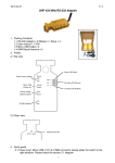
6500RTS-KEY INSTALLATION AND
OPERATING INSTRUCTIONS
GENERAL DESCRIPTION
The 6500RTS-KEY is a remote annunciator and control unit
for use with the 6500 range of projected beam smoke
detectors. It is ideal for installations where access to the
detector is restricted.
A three position key switch provides remote test and reset
functions. The key may only be removed in the central neutral
position in order to prevent accidentally leaving the detector in
test status. Rotating the switch clockwise from the central
position operates the detector's remote test function. Reset is
achieved by rotating the switch anti-clockwise. The reset
position is a momentary type switch to prevent the detector
being left in a disabled state.
The 6500RTS-KEY is equipped with two LED's to indicate the
detector's status. When the detector reports a FIRE condition
the red LED will be illuminated mimicking the detector's LED,
and a FAULT condition is indicated by the yellow LED.
SPECIFICATIONS
Dimensions (Flush):
87mm x 87mm x 52mm (H x W x D)
Dimensions (Surface): 87mm x 87mm x 64mm (H x W x D)
Weight:
178g
Operating Temperature: -30°C to 70°C
Ingression Protection: IP40
MOUNTING INSTRUCTIONS
Flush Mounting
The 6500RTS-KEY may be mounted into standard UK type
single switch / socket back boxes. Ensure that the plastic
spacer supplied is fitted between the back box and 6500RTSKEY.
Surface Mounting
A plastic mounting box is supplied for surface mounting. This
is fixed to the wall using suitable fastenings (see fig 1 for
fixing centres). The plastic spacer and 65600RTS-KEY are
then mounted directly to the box using the fixing screws
supplied.
WIRING
See figure 2.
Note: Refer to the Maintenance and Wiring sections of the
Beam Detector Installation and Maintenance Instructions for
additional information.
Figure 1: Back Box Mounting Centres
51
87 mm
m
m
87 mm
Figure 2: 6500RTS-KEY Wiring
Beam Detector
FAULT
FIRE
TEST
D 698
0
RESET
GREEN
T2-1: REMOTE ALARM OUTPUT
ORANGE
6500R(S) - T3-3: REMOTE TROUBLE OUTPUT
6500(S) - NOT CONNECTED
BLACK
T2-2: AUX (-)
RED
T2-4: RESET INPUT
YELLOW
T2-2: AUX (-)
YELLOW
T2-3: TEST INPUT
1
© System Sensor 2004