1
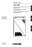
MV electrical network management
Easergy range
Flair 200C
English
Manuel d’installation
Installation manual
Installationshandbuch
Français
MV substation remote monitoring unit
TX
RX
1
Deutsch
English
2
Easergy
Flair 200C
Flair 200C
Sommaire
Présentation
Description des fonctions
Caractéristiques mécaniques
Architecture
4
6
7
Capteurs de courant
Câblage d’entrées/sorties
Equipements de transmission
8
9
10
Choix des équipements
Raccordements
Alimentation du coffret
NT00202-FR-EN-DE-05
13
3
Français
Installation
Description des fonctions
Présentation
DE58880
Le Flair 200C est un outil efficace dans la réduction des temps d’intervention et de
recherche des défauts. Il améliore la qualité de service de la distribution de l’énergie.
Principales fonctions du Flair 200C
Ces fonctions sont disponibles sur une voie en version de base et sur 2 voies
en option.
TX
RX
1
2
Détection et mémorisation des défauts phase et terre
Français
b
v
v
b
b
b
Easergy
Flair 200C
2 possibilités de détection de défaut :
détection ampèremétrique
ou, en option, détection ICC pour les réseaux à neutre compensé.
Enregistrer les informations issues de 6 entrées digitales
Envoyer des commandes via 3 sorties
Transmettre les informations à distance.
Il dispose également de fonctions permettant une meilleure gestion et planification
des réseaux :
b Mesures et enregistrement des courants de charges sur la ligne MT.
b Mesures et enregistrement de la tension MT à partir de la tension BT
(si l’option mesure de puissances est installée)
b Calcul des puissances P, S, Q, de l’énergie et du facteur de puissance
(si l’option mesure de puissances est installée).
Evénements Enregistrés Datés (EED) :
Enregistrement chronologique horodaté des événements et des mesures.
Ces informations peuvent être transmises au centre de conduite et/ou archivées
dans des journaux pour consultation et téléchargement local (sous forme
de fichiers .xls), par connexion d’un micro-ordinateur.
Alimentation sauvegardée
En cas de perte d’alimentation, une batterie plomb assure une autonomie de 4 h.
L’alimentation est vérifiée en permanence. Des alarmes peuvent être envoyées
au Scada en cas de :
b Manque secteur immédiat
b Défaut chargeur
b Défaut batterie.
Communication en local et vers un centre de téléconduite
Le Flair 200C comprend en standard
b Un port USB de communication avec le PC local pour consultation/configuration.
Le Flair 200C peut recevoir en option
b Un port Ethernet pour la communication vers le centre de téléconduite
ou pour l’accès depuis le PC local de consultation/configuration.
b
v
v
v
v
v
v
Un modem pour la communication distante vers le centre de téléconduite :
GSM/GPRS
GSM/3G - UMTS & HSPA + (3,75G), EDGE, GPRS & GSM
RTC
Radio
RS485/RS422
RS232.
b Un modem RS232 ou RS485/RS422 peut dialoguer en protocole Modbus
avec des équipements locaux type Sepam. Le Flair 200C joue alors le rôle
de concentrateur.
b
v
v
v
v
Tous les protocoles de communication sont possibles avec le centre de téléconduite :
CEI 870-5-101, CEI 870-5-104
DNP3, DNP3/IP
Modbus, Modbus/IP
Autres protocoles sur demande.
Synchronisation horaire de l’équipement
La mise à l’heure pour la datation des événements peut se faire :
b Par le PC portable de consultation/configuration du Flair 200C (manuellement ou
automatiquement avec l’heure du PC)
b Par le centre de téléconduite
b Par synchronisation SNTP à partir d’un réseau Ethernet (précision de la mise
à l’heure de l’ordre de la seconde).
4
NT00202-FR-EN-DE-05
Présentation
Description des fonctions
Automate programmable IEC61131-3
Français
En option, le Flair 200C peut inclure un automate virtuel programmable embarqué
IEC 61131-3.
Une plateforme de développement (le logiciel RTU Control livré en annexe sur
le CD Easergy) permet de concevoir, simuler et tester sur cible des programmes
écrits dans les langages automates suivants :
b SFC – Sequential Function Chart
b FBD – Function Block Diagram
b LD – Ladder Diagram
b ST – Structured Text
b IL– Instruction List
Ces programmes automates permettent de réaliser des applications spécifiques
et personnalisées ou des fonctions additionnelles au Flair 200C par combinaison
ou action sur des variables existantes Flair 200C ou des variables virtuelles à créer
spécifiquement pour l’application automate.
Communication interéquipement
L’option automatisme programmable IEC61131-3 inclut également une fonction de
communication entre équipements, permettant un échange Modbus, via une liaison
TCP/IP, entre des Flair 200C connectés sur une même boucle MT.
Cette communication permet l’échange d’une table de données entre ces Flair 200C,
afin de contribuer par exemple (sans autre automate que les Flair 200C) à une
fonction d’automatisme permettant la détection et l’élimination d’un défaut courant
sur une boucle MT.
Cette communication interéquipement est typiquement utilisée dans les applications
de type réseau autocicatrisant.
Formules de calcul
Les formules de calcul sont disponibles en standard dans le Flair 200C.
Elles peuvent être utilisées dans le Flair 200C pour créer de nouvelles fonctions ou
applications personnalisées ne nécessitant pas l’écriture d’un programme en
langage automate.
Les fonctions qu’il est possible d’utiliser dans les formules sont :
b Fonctions mathématiques
b Fonctions statistiques
b Fonctions logiques
b Fonctions horaires/dates
b Etc.
Ces formules permettent, de façon plus simplifiée qu’un programme automate,
la création d’équations logiques basées sur des combinaisons de variables.
Les types de variables pouvant être utilisées sont les mêmes que pour les
programmes automates (variables existantes Flair 200C ou variables virtuelles
créées spécifiquement).
(Pour plus de détails sur ces trois fonctions, consulter la notice spécifique
“RTU Control & Formules” – réf. NT00320-xx).
NT00202-FR-EN-DE-05
5
Caractéristiques mécaniques
Présentation
DE58883FR
Dimensions et masse
210
b Dimensions : voir schéma ci-contre
b Masse : environ 2,5 kg suivant les options.
104
Stockage
b Températures de fonctionnement : – 20 °C à + 70 °C
b Températures de stockage : – 40 °C à + 70 °C
L’appareil doit être stocké avec la batterie déconnectée.
Ne pas laisser la batterie plus de 6 mois sans la recharger.
Français
334
Identification du produit
Le numéro de série et référence du produit sont indiqués sur une étiquette située
sur le côté droit du socle.
Fixation du boîtier
Fentes de fixation
pour bandes d’acier
Ouvrir l’appareil à l’aide des pattes de clipsage situées en bas du boîtier. Pour cela,
pousser les pattes vers l’intérieur tout en soulevant la partie supérieure du coffret.
4 trous pour vis Ø 6
DE58884
175
269
DE58894
Ouvrir le boitier au maximum puis faire coulisser les deux pivots glissants vers
l’arrière du boitier afin de bloquer celui-ci en position ouverte.
Fixer le socle à l’aide de vis Ø 6 mm. Un gabarit de perçage est fourni avec le produit.
Pivots coulissants
6
NT00202-FR-EN-DE-05
Architecture
Présentation
DE58881
Emplacement des constituants du Flair 200C
Carte CPU
Français
Bouton-poussoir :
b TEST : déclenche un appel vers le SCADA
b RESET de la détection de défaut si un défaut
est présent.
Led d’indication d’état
Connecteur d’entrées/sorties
Support de carte SIM (modem GSM/GPRS)
Carte modem GSM/GPRS
Cartes de communication (3 emplacements)
Connecteur de l’antenne GSM/GPRS
Connecteur USB type B
PE
Bornier de terre
Connecteur batterie
Batterie
Connecteur des tores (voie 1)
Connecteur des tores (voie 2 en option)
+ – + –
A: COM I3 I2 I1
BC: COM IØ I3 I1
N
L
Connecteur voyant extérieur
Connecteur d’alimentation
Obturateurs / Passe fils
DE58882
Fentes d’insertion des attaches rapides pour la
fixation des câbles
Préconisation d’utilisation des presse-étoupes :
1
2
3
4
5
6
7
Entrée/sortie ou port local Modbus ou Ethernet
Antenne GSM
BVE
Terre
Entrée tores voie 2
Entrée tores voie 1
Entrée alimentation BT
NT00202-FR-EN-DE-05
1
5
2
6
4
3
7
8
7
Capteurs de courant
Installation
b Tores phases
et homopolaire
ouvrants standard
MF1 et MFH
Le Flair 200C est compatible avec les capteurs de courant de la gamme de détecteur
de courant de défaut Easergy Flair 2xx et Easergy T200.
b Tores phases
et homopolaire résinés
haute performance
Le Flair 200C est également compatible avec tous les types de capteurs du marché.
Selon le type de kit, le montage concernera :
b 3 tores phases ouvrants
b 2 tores phases ouvrants + 1 tore homopolaire
b 1 tore homopolaire.
H
A
U
T
P
TO
DE56406
Raccordement des tores au Flair 200C
Français
Pour raccorder le câble de liaison des tores, il faut :
b Utiliser un câble 4 x 1,5 mm2 U1000RO2V (non fourni)
b Faire passer le câble par le presse-étoupe associé
b Resserrer le presse-étoupe.
DE58887FR
Le connecteur 4 points du câble venant des tores est à raccorder sur la carte
d’acquisition courant de la voie concernée (voie 1 ou voie 2) selon le schéma
ci-dessous.
Montage
“type A”
com Io I3 I1
com I3 I2 I1
DE58885
Montage
“type B”
L1 L2 L3 N
Montage
“type C”
monotore
com Io I3 I1
L1 L2 L3
L1 L2 L3
Mise en place des tores dans la cellule
L1
L2
Les tores doivent être installés sur les câbles en respectant impérativement
le sens de positionnement : repérage HAUT/TOP vers le haut ou couleur identique
vers le haut.
L3
d Attention : si l’option puissance est installée : installer les tores dans la cellule
en respectant l’ordre des phases (phase 1 raccordée au connecteur I1, phase 2
raccordée au connecteur I2, phase 3 raccordée au connecteur I3 du Flair 200C).
d IMPORTANT :
b Le blindage de chaque câble MT doit repasser à l’intérieur du tore
correspondant avant d’être relié à la terre (voir schéma ci-contre).
b L’isolement basse tension des tores Easergy n’autorise leur emploi
que sur des câbles isolés.
b Les câbles de tension nominale supérieure à 1000 V doivent avoir un écran
relié à la terre.
b Les montages types A et B ne sont pas autorisés sur les câbles tripolaires.
I1
I2
I3
DE58901
DE58902
Mise en place de 3 tores phases ouvrants
Montage CORRECT avec un câble tripolaire
8
Montage NON CORRECT avec un câble tripolaire
NT00202-FR-EN-DE-05
Câblage d’entrées/sorties
Installation
DE55031
DE58888
Raccordement d’un voyant extérieur
1 2 3 4
+ –
Le voyant extérieur (option) permet de visualiser le passage d’un courant de défaut.
b Raccordement par câble 1,5 mm2 (non fourni)
b Entrer le câble par le presse-étoupe correspondant sur la base du coffret
b Raccorder le câble sur les 2 bornes à visser prévues à cet effet.
d
Attention : les bornes à raccorder sont polarisées.
Respecter le sens de connexion “+” et “–”.
Français
Nota : les bornes 3 et 4 ne doivent pas être raccordées. Celles-ci ne sont pas
utilisées.
Raccordement d’entrées/sorties digitales
b 6 entrées et 3 sorties sont disponibles pour l’acquisition ou la commande
d’informations tout ou rien (alarme porte, …).
b Entrer le câble par le presse-étoupe correspondant sur la base du coffret.
b Raccorder le câble sur les bornes à visser prévues à cet effet
(voir schéma ci-contre et page 6).
Sorties doubles
DO 1-2
DO3
DO2
DE58899
DO1
NT00202-FR-EN-DE-05
1
2
3
4
5
6
7
8
9
10
11
12
13
Spécifications des entrées
b Boucle sèche (polarisation interne en 5 V)
b Non isolées (protection par transil)
b Fréquence pour comptage : jusqu’à 5 Hz
b Possibilité de déclarer une entrée de type FPI (dans ce cas, la lampe externe
clignotera quand l’entrée est active. A utiliser lorsque le détecteur de défaut est
externe et que le Flair 200C n’agit que comme simple organe de transmission
des données).
Spécifications des sorties
b Contacts secs isolés à 1,5 kVeff par rapport à la masse. Pas d’isolation entre les
sorties
b Charge limite : 30 VA / limité à 60 Vcc ou 125 Vca
Possibilité de déclarer une sortie de type :
b Impulsion : dans ce cas, le fait d’activer une sortie génèrera une impulsion
pendant une durée d’activation paramétrable.
A utiliser lorsque le détecteur de défaut est externe et que le Flair 200C n’agit que
comme simple organe de transmission des données. La sortie sera utilisée afin
de réinitialiser le détecteur.
b Double : 2 sorties digitales sont utilisées. Cette option offre une solution bon
marché pour piloter certains interrupteurs grâce à des commandes double-bit
(nécessite un relayage adapté à la sortie du Flair 200C).
9
Equipements de transmission
Installation
DE58895-1
Choix des équipements
Le Flair 200C offre différents types de communications grâce à des cartes
additionnelles qui se connectent sur la carte CPU.
Le Flair 200C peut recevoir jusqu’à 3 cartes additionnelles en fonction des options
choisies.
Carte CPU
Equipement de base
Carte sur emplacement droit
Français
b Un port USB de type B.
Il est utilisé avec un PC local pour la maintenance et le paramétrage.
Equipements en option
Carte sur emplacement droit
GSM/GPRS Ethernet
USB type B
RS232/
RS485
GSM/3G
b Un port Ethernet utilisé pour :
v la communication vers le centre de téléconduite via les protocoles CEI 60870-5-104,
DNP3 IP ou Modbus IP
v la communication vers des esclaves Modbus TCP (automates, relais de
protection…). Le Flair 200C joue alors le rôle de concentrateur
v la maintenance et le paramétrage à partir d’un PC local.
Le port Ethernet est placé sur la carte du port USB.
Carte sur emplacement central
Un modem pour la communication distante vers le centre de téléconduite :
b GSM/GPRS : quadribande version 850/900/1800/1900 MHz
Nota : le modem GSM/GPRS est intégré à la carte CPU. A la différence des autres
modems, celui-ci n’est pas interchangeable
b GSM/3G : GSM/GPRS/EDGE : quadribande, 850/900/1800/1900 MHz
UMTS/HSPA+ : pentabande, 800/850/AWS/1900/2100 MHz
b RTC isolé à 8 kVeff. (300 à 14400 bits/s - V32 bis)
RS232
RTC
b Radio (FSK 600/1200 bauds ou FFSK 1200/2400 bauds)
(radio non fournie avec le produit)
b RS232/RS485 isolée à 2 kVeff.
b RS232 non isolée.
Carte sur emplacement gauche
Un port permet de dialoguer en protocole Modbus avec des équipements locaux
type Sepam. Le Flair 200C joue alors le rôle de concentrateur.
b RS232/RS485 isolée à 2 kVeff.
Radio FSK
b RS232 non isolée.
ou FFSK
Protocoles de communication
Tous les protocoles de communication sont possibles avec le centre de téléconduite :
b CEI 870-5-101, CEI 870-5-104
b DNP3, DNP3/IP
b Modbus, Modbus/IP
b Autres protocoles sur demande.
RS232/
RS485
RS232
10
NT00202-FR-EN-DE-05
Equipements de transmission
Installation
DE58906
Raccordements
Modem GSM/3G
d Toute intervention sur le Flair 200C s’effectue hors tension.
Tous les connecteurs et équipements installés sont accessibles sur la carte CPU
en ouvrant le couvercle du Flair 200C.
Support de
carte SIM
Connecteur USB
Prise antenne
Connecteur Ethernet
Nécessite un câble USB-A/USB-B pour la communication avec un PC local
pour consultation/configuration.
Mise en fonction d’un modem GSM/GPRS ou GSM/3G (interne)
Support de
carte SIM
Modem GSM/GPRS
DE58890
SIM
La prise d’antenne et le support de carte SIM sont placés à côté du modem
(voir dessin ci-contre).
b Fixer l’antenne sur le mur du poste (de préférence à l’extérieur)
b Raccorder le câble d’antenne sur la prise antenne du modem
b Introduire la carte SIM (voir dessins ci-contre)
v GSM/3G
- déverrouiller le chariot support de la carte SIM en poussant à fond le bouton
extracteur
- sortir le chariot support et insérer la carte SIM à l’intérieur (angle coupé en bas
et à droite)
- remettre le chariot support en place en le poussant à fond dans son emplacement.
v GSM/GPRS
- déverrouiller le volet support de la carte SIM en poussant vers le bas la partie
métallique
- soulever le volet et glisser à l’intérieur de ce volet, sous la partie métallique,
la carte SIM (angle coupé en haut et à gauche)
- refermer et reverrouiller le volet support de la carte SIM.
Raccordement d’une ligne RTC
Raccorder la ligne RTC sur les 2 bornes prévues
à cet effet.
DE58892
SIM
Connecteur sur carte RTC
PE
Connecteur
USB type B
Connecteur
Ethernet
Prise antenne du modem
Raccorder la ligne RS485 ou RS422 selon le schéma
du connecteur type RJ45 ci-contre.
Connexion RS485 2 fils
1, 2, 3, 6, 7 : non utilisé
4 :A
5:B
8 : GND
DE58891
Raccordement RS485 ou RS422 vers le superviseur
Connexion RS422
1 : Rx (B)
2 : Rx (A)
3, 6, 7 : non connecté
4 : Tx (A)
5 : Tx (B)
8 : GND
8
7
6
5
4
3
2
1
Connecteur côté modem
Raccorder la ligne RS232 selon le schéma
du connecteur type RJ45 ci-contre.
Ø 16
379
Câble longueur 5 m
DE58893
Raccordement RS232 vers le superviseur
8
7
6
5
4
3
2
1
GND
DCD
RTS
DSR
DTR
CTS
RXD
TXD
Connecteur côté modem
Antenne
bidirectionnelle
2 trous Ø 6
Raccordement au réseau Modbus local
38 106
26
NT00202-FR-EN-DE-05
Les ports de communication RS232 et RS485 avec protocole Modbus peuvent
dialoguer avec des équipements locaux Modbus (type Sepam par exemple).
Le Flair 200C joue alors le rôle de concentrateur.
La connexion est identique aux raccordements types RS232, RS485 ou RS422
détaillé ci-dessus.
11
Français
Nécessite un câble Ethernet “croisé” ou “droit” suivant le type de liaison
(voir chapitre “Connexion du serveur” dans le manuel utilisateur réf. : NT00201).
Bouton
extracteur
Equipements de transmission
Installation
Raccordements
Raccordement à l’émetteur/récepteur
radio analogique
Raccordement modem externe RS232
(RTC, radio modem, GSM…)
(accessible sur le connecteur RJ45 de la carte radio
modem interne)
(accessible sur connecteur RJ45 8 broches situé sur la carte RS232)
Flair 200C (RJ45)
Radio
0V 1
Flair 200C
1 Réserve
BF Rec 2 o–––––––––o 2 BF réception
0V 3 o–––––––––o 3 Masse
0V 4
Flair 200C
4 Réserve
Modem
TX 1 o––––o 3 TX - Transmission de données
RX 2 o––––o 2 RX
RX 2 o––––o 2 RX - Réception de données
GND 8 o––––o 5 GND
BF Em 8 o–––––––––o 5 BF émission
Français
Modem
TX 1 o––––o 3 TX
GND 8 o––––o 5 GND - Masse
RTS 6 o––
7 RTS
RTS 6 o––––o 7 RTS - Demande d’émission
CTS 3 o––
8 CTS
CTS 3 o––––o 8 CTS - Prêt à émettre
Cde Em 5 o–––––––––o 6 Cde émission
DTR 4 o––
4 DTR
DTR 4 o––––o 4 DTR - Terminal de données prêt
Squelch 6 o–––––––––o 7 Squelch
DSR 5 o––
6 DSR
DSR 5 o––––o 6 DSR - Données prêtes
DCD 7 o––
1 DCD
NC 7
8 Réserve
DE56299
9 Réserve
DCD 7 o––––o 1 DCD - Détection de porteuse
Pas de gestion de CTS, DCD, DSR
Gestion de CTS, DCD, DSR
1
Exemple de raccordement avec une radio numérique MDS 4710
(cordon précâblé en usine : CB-00168)
8
Connecteur RJ45 sur
câble de liaison radio
Flair 200C (RJ45)
CB-00168
MDS (DB25-M)
DP (DCD) 7 o–––––––––o 8 DP (DCD)
RD (RX) 2 o–––––––––o 3 RD (RX)
TD (TX) 1 o–––––––––o 2 TD (TX)
Exemple de raccordement avec une radio
analogique Motorola GM340
Flair 200C (RJ45)
NC 4
9 NC
GND 8 o–––––––––o 7 GND
GM340
CPD (DSR) 5 o–––––––––o 6 CPD (DSR)
Cde émission 5 o–––––––––o 3 Alternat données
DPE (RTS) 6 o–––––––––o 4 DPE (RTS)
BF émission 8 o–––––––––o 5 BF TX
PAE (CTS) 3 o–––––––––o 5 PAE (CTS)
0V 3 o–––––––––o 7 0V
BF réception 2 o–––––––––o 11 BF RX
DE56243
8
11
7 5 3
DE56299
1 Ecran
Squelch 6 o–––––––––o 8 Détection porteuse
1
8
Connecteur RJ45
sur câble CB-00168
Connecteur radio GM340
Vue côté câble
Exemple de raccordement avec une radio
analogique TAIT 811x
(cordon précâblé en usine : CB00121)
Flair 200C (RJ45)
NC 1
CB00121
TAIT 811x (15 pts)
1 NC
a
BF réception 2 o–––––––––o
13 BF réception
GND 3 o–––––––––o 15 GND
b
NC 4
3 NC
+
BF émission 8 o––––––|c|––o
7 BF émission
Cde émission 5 o–––––––––o 12 Cde émission
Squelch 6 o–––––––––o 10 Squelch
NC 7
8 NC
9 NC
Masse
a = résistance 1/4W 5 % 2,2 kΩ
b = résistance 1/4W 5 % 820 Ω
c = condensateur électrolytique 4,7 µF/63 V
NC = Non Connecté.
12
NT00202-FR-EN-DE-05
Alimentation du coffret
Installation
d Afin d’éviter des risques d’électrocution ou de brûlures, vérifier que la tension
du secteur est bien coupée avant d’intervenir sur le produit.
Raccordement de la terre
d
Français
Il est important pour la sécurité des personnes de raccorder le coffret
à la terre.
Un bornier à vis est prévu à cet effet sur la carte Flair 200C.
Utiliser un câble terre de section supérieure ou égale à 4 mm2 U1000RO2V
ou équivalent.
Raccordement de U alternatif
d
Afin d’éviter des risques d’électrocution ou de brûlures, vérifier que la
tension du secteur est bien coupée avant d’intervenir sur le coffret.
b Entrer le câble “U alternatif” (2 x 2,5 mm2) par le presse-étoupe correspondant
et le raccorder au plus court sur les bornes à visser prevues à cet effet
b Echelle d’entrée : 120/240 Vca –20 %/+10 % - 50/60 Hz
b Connecter le câble d’une phase au terminal “L” et celui du neutre au terminal “N”
b L’alimentation AC doit être issue de l’aval d’un coupe-circuit HPC (haut pouvoir de
coupure).
d
IMPORTANT : l’entrée “U alternatif” est isolée à 10 kVeff. par rapport
à la masse du coffret. Il est important que le câble utilisé et sa mise en œuvre,
à l’extérieur et dans le produit, ne dégradent pas cet isolement.
Mise en place de la batterie
DE58881
La batterie est de type 4 V – 2,5 Ah. Elle prend place dans la partie gauche du coffret
(voir dessin ci-contre). Connecter la batterie sur le connecteur prévu à cet effet.
Bornier de terre
PE
Connecteur batterie
Batterie
Connecteur d’alimentation
A: COM I3 I2 I1
BC: COM IØ I3 I1
NT00202-FR-EN-DE-05
+ – + –
N
L
13
Français
Notes
14
NT00202-FR-EN-DE-05
Flair 200C
Contents
Overview
Description of functions
Mechanical properties
Architecture
4
6
7
Installation
Current sensors
Input/output wiring
Transmission equipment
8
9
10
Choice of equipment
Connections
13
English
Enclosure power supply
NT00202-FR-EN-DE-05
3
Description of functions
Overview
DE58880
The Flair 200C is an efficient tool for reducing repair and fault finding times.
It improves quality of service for power distribution.
Main functions of the Flair 200C
These functions are available on one channel in the standard version and
on 2 channels on option.
TX
RX
1
2
Detection of phase and earth faults and storage in memory
b
v
v
b
b
b
Easergy
Flair 200C
2 possibilities for fault detection:
ammetric detection
or, optionally, ICC detection for compensated neutral networks.
Recording of the information coming from 6 digital inputs
Sending commands via 3 outputs
Remote data transmission.
It also has functions allowing improved network management and planning:
b Measurement and recording of load currents on the MV line
b Measurement and recording of the MV voltage from the LV voltage
(if the power measurement option is installed)
b Calculation of power (P, S, Q), energy and power factor
(if the power measurement option is installed).
Dated logging events:
English
Time-stamped chronological logging of events and measurements.
This information can be transmitted to the supervision centre and/or archived
in logs for consultation and local downloading (in the form of .xls files),
by connecting a microcomputer.
Backed-up power supply
In the event of a power outage, a lead battery provides a 4-hour power reserve.
The power supply is checked constantly. Alarms can be sent to the Scada system
in the event of:
b Immediate mains failure
b Charger fault
b Battery fault.
Local communication and communication with a remote
supervision centre
The Flair 200C includes as a standard feature
b A USB port for communication with the local PC for consultation/configuration.
The Flair 200C can receive as optional features
b An Ethernet port for communication with the remote supervision centre and
for access from the local consultation/configuration PC.
b
v
v
v
v
v
v
One modem for remote communication with the remote supervision centre:
GSM/GPRS
GSM/3G - UMTS & HSPA + (3.75G), EDGE, GPRS & GSM
PSTN
Radio
RS485/RS422
RS232.
b A RS232 or RS485/RS422 modem can communicate in Modbus protocol
with Sepam type local devices. In that case the Flair 200C plays the role of hub.
b
v
v
v
v
All communication protocols can be used with the remote supervision centre:
IEC 870-5-101, IEC 870-5-104
DNP3, DNP3/IP
Modbus, Modbus/IP
Other protocols on request.
Time synchronization of the equipment
Time setting for event dating can be performed:
b By the laptop PC for consultation/configuration of the Flair 200C
(manually or automatically with the PC time)
b By the remote supervision centre
b By SNTP synchronization from an Ethernet network
(time setting precision of approximately one second).
4
NT00202-FR-EN-DE-05
Overview
Description of functions
IEC 61131-3 programmable logic controller
On option, the Flair 200C can include an IEC 61131-3 embedded virtual
programmable logic controller.
A development platform (the RTU Control software supplied in appendix on the
Easergy CD) makes it possible to design, simulate and test on a target programs
written in the following PLC languages:
b SFC – Sequential Function Chart
b FBD – Function Block Diagram
b LD – Ladder Diagram
b ST – Structured Text
b IL – Instruction List
These PLC programs allow specific customized applications or additional functions
to be implemented on the Flair 200C by combining or actuating existing Flair 200C
variables or virtual variables to be created specifically for the PLC application.
Inter-equipment communication
Calculation formulae
The calculation formulae are a standard feature of the Flair 200C.
They can be used in the Flair 200C to create new customized functions or
applications not requiring writing of a program in PLC language.
The functions that can be used in the formulae are:
b Mathematical functions;
b Statistical functions;
b Logical functions;
b Time/date functions;
b etc.
These formulae make it possible, more easily than with a PLC program, to create
logic equations based on combinations of variables. The types of variables that can
be used are the same as for PLC programs (existing Flair 200C variables or virtual
variables created specifically). This inter-equipment communication is typically used
in applications of the self-healing network type.
(For more details regarding these three functions, refer to the specific "RTU Control
& Formulae" manual – ref. NT00320-xx).
NT00202-FR-EN-DE-05
5
English
The IEC 61131-3 programmable automatic control option also includes an interequipment communication function, allowing Modbus exchange, via a TCP/IP link,
between Flair 200C devices connected to the same MV circuit. This communication
allows exchange of a data table between these Flair 200C devices, in order to
contribute, for example (without any other PLC than the Flair 200C's), to an
automatic control function allowing detection and clearing of a current fault on an MV
circuit.
Mechanical properties
Overview
DE58883EN
Dimensions and weight
210
b Dimensions: see diagram opposite
b Weight: about 2.5 kg depending on options.
104
Storage
b Service temperatures: –20°C to +70°C
b Storage temperatures: –40°C to +70°C
The device must be stored with the battery disconnected.
Do not leave the battery more than six months without recharging it.
334
Product identification
The serial number and product reference are indicated on a label located
on the right-hand side of the base.
Enclosure mounting
Mounting slots
for steel strips
Open the device using the clips located at the bottom of the enclosure.
To do so, push the clips inward while raising the upper part of the enclosure.
4 holes for screws of Ø 6
English
DE58884
175
269
DE58894
Open the enclosure as far as possible, then slide the two sliding pivots to the back of
the enclosure to block it in the open position.
Fix the base with screws Ø 6 mm. A drilling template is supplied with the product.
sliding pivots
6
NT00202-FR-EN-DE-05
Architecture
Overview
DE58881
Location of Flair 200C components
CPU card
Push button:
b TEST: triggers a call to the SCADA
b RESET fault detection if a fault is present.
Status indication LED
Input/output connector
SIM card slot (GSM/GPRS modem)
GSM/GPRS modem card
English
Communication cards (3 slots)
GSM/GPRS antenna connector
Type B USB connector
PE
Earth terminal block
Battery connector
Battery
Toroid connector (channel 1)
Toroid connector (optional channel 2)
+ – + –
A: COM I3 I2 I1
BC: COM IØ I3 I1
N
L
External indicator connector
Power supply connector
Covers / Cable grommets
DE58882
Quick fastener insertion slots
for cable mounting
Recommendation for use of cable glands:
1
2
3
4
5
6
7
Modbus or Ethernet input/output or local port
GSM antenna
External indicator terminal
Earth
Channel 2 toroid input
Channel 1 toroid input
LV power supply input
NT00202-FR-EN-DE-05
1
5
2
6
4
3
7
8
7
Current sensors
Installation
b MF1 and MFH standard
split phase and homopolar
toroids
The Flair 200C is compatible with the current sensors of the Easergy Flair 2xx and
Easergy T200 fault passage indicator range.
The Flair 200C is also compatible with all types of commercially available sensors.
Connection of toroids to the Flair 200C
H
A
U
T
P
TO
DE56406
b High-performance
resin-coated phase and
homopolar toroids
Depending on the type of kit, the setup will concern:
b 3 split phase toroids
b 2 split phase toroids + 1 homopolar toroid
b 1 homopolar toroid.
To connect the toroid connecting cable:
b Use a 4 x 1.5 mm2 cable, U1000RO2V (not supplied)
b Insert the cable through the associated cable gland
b Tighten the cable gland.
English
DE58887EN
The 4-pin connector of the cable coming from the toroids is to be connected
to the current acquisition card for the channel in question (channel 1 or channel 2)
in accordance with the following diagram.
“Type A”
setup
com Io I3 I1
com I3 I2 I1
DE58885
“Type B”
setup
L1 L2 L3 N
“Type C”
setup
single toroid
com Io I3 I1
L1 L2 L3
L1 L2 L3
Installing toroids in the enclosure
L1
L2
When fitting the toroids on the cables, it is essential to comply with the direction
of positioning: HAUT/TOP marking facing upward or identical colour facing upward.
L3
d NB: if the power option is installed: install the toroids in the enclosure complying
with the phase order (phase 1 connected to connector I1, phase 2 connected to
connector I2, phase 3 connected to connector I3 of the Flair 200C).
d IMPORTANT NOTE:
b The shielding of each MV cable must be re-inserted inside the corresponding
toroid before being connected to earth (see diagram opposite).
b The low-voltage insulation of the Easergy toroids means they can only be
used on insulated cables.
b Cables of voltage rating greater than 1000 V must have a shield connected
to earth.
b The type A and B setups are not authorized on three-pole cables.
I1
I2
I3
DE58901
DE58902
Installation of three split phase toroids
CORRECT setup with a three-pole cable
8
INCORRECT setup with a three-pole cable
NT00202-FR-EN-DE-05
Input/output wiring
Installation
DE58888
DE55031
Connecting an external indicator lamp
1 2 3 4
+ –
The external indicator lamp (optional) is used to indicate a fault current.
b Connection by 1.5 mm2 cable (not supplied)
b Insert the cable via the corresponding cable gland on the base of the enclosure
b Connect the cable to the 2 screw terminals provided for the purpose.
d
NB: the terminals to be connected are polarized.
Comply with the direction of connection “+” and “–”.
Note: terminals 3 and 4 should not be connected. These are not used.
Connection of digital inputs/outputs
b 6 inputs and 3 outputs are available for acquisition and control of digital
information (door alarm, etc.)
b Insert the cable via the corresponding cable gland on the base of the enclosure.
b Connect the cable to the screw terminals provided for the purpose (see diagram
opposite and page 6).
DO2
DE58899
DO1
NT00202-FR-EN-DE-05
1
2
3
4
5
6
7
8
9
10
11
12
13
Output specifications
b Dry contact insulated at 1.5 kV rms to the earth. No insulation between outputs
b Limit load: 30 VA / limited to 60 Vdc or 125 Vac.
Capability for declaring the type of output:
b Pulse: in this case, the fact of activating an output will generate a pulse during
a configurable activation period.
To be used when the fault detector is external and when the Flair 200C acts merely
as a simple data transmission device. The output will be used to reinitialize the detector.
b Double: 2 digital outputs are used. This option offers a cheap solution to open/close
some switches thanks to double-bits commands (requires the use of a power relay
outside the Flair 200C).
9
English
DO3
Double output
DO 1-2
Input specifications
b Dry loop (internal polarization at 5 V)
b Non-insulated (protection by transil)
b Frequency for counting: up to 5 Hz
b Capability for declaring an FPI type input (in this case, the external lamp will flash
when the input is activated. To be used when the fault detector is external and when
the Flair 200C acts merely as a simple data transmission device).
Transmission equipment
Installation
Choice of equipment
DE58895-1
The Flair 200C offers various types of communications via add-on cards which are
connected to the CPU card.
The Flair 200C can receive up to 3 add-on cards depending on the options selected.
CPU card
Standard equipment
Card on right-hand slot
b A type B USB port.
This is used with a local PC for maintenance and parameters setup.
Optional equipment
Card on right-hand slot
GSM/GPRS Ethernet
USB type B
b An Ethernet port used for:
v communication with the remote supervision centre via the IEC 60870-5-104,
DNP3 IP or Modbus IP protocols
v communication with Modbus TCP slaves (PLCs, protection relays…).
In that case, the Flair 200C plays the role of hub
v maintenance and parameters setup from a local PC.
The Ethernet port is located on the card of the USB port.
RS232/
RS485
GSM/3G
Card on centre slot
A modem for remote communication with the remote supervision centre:
English
b GSM/GPRS: quad band 850/900/1800/1900 MHz version
Note: the GSM/GPRS modem is integrated in the CPU card. Unlike other modems,
this one is not interchangeable
b GSM/3G: GSM/GPRS/EDGE: quad band, 850/900/1800/1900 MHz
UMTS/HSPA+: five band, 800/850/AWS/1900/2100 MHz
b PSTN insulated at 8 kV rms (300 to 14400 bits/s - V32 bis)
RS232
PSTN
b Radio (FSK 600/1200 baud or FFSK 1200/2400 baud)
(radio not supplied with the product)
b RS232/RS485 insulated at 2 kV rms
b RS232 non-insulated.
Card on left-hand slot
A port allows communication in Modbus protocol with Sepam type local devices.
In that case the Flair 200C plays the role of hub.
b RS232/RS485 insulated at 2 kV rms.
b RS232 non-insulated.
Radio (FSK
or FFSK)
Communication protocols
All communication protocols can be used with the remote supervision centre:
b IEC 870-5-101, IEC 870-5-104
b DNP3, DNP3/IP
b Modbus, Modbus/IP
b Other protocols on request.
RS232/
RS485
RS232
10
NT00202-FR-EN-DE-05
Transmission equipment
Installation
DE58906
Connections
d All servicing on the Flair 200C is performed with the power off.
GSM/3G modem
All the installed connectors and equipment are accessible on the CPU card by opening
the cover of the Flair 200C.
SIM card slot
USB connector
Requires a USB-A/USB-B cable for communication with a local PC for consultation/
configuration.
Antenna connector
Ethernet connector
Requires a “cross” or “straight” Ethernet cable depending on the type of connection
(see “Server connection” chapter in the User Manual ref. NT00201).
Button/
extractor
Operating start-up of a GSM/GPRS or GSM/3G modem (internal)
GSM/GPRS modem
Connection of a PSTN line
Connect the PSTN line to the 2 terminals provided
for the purpose.
English
SIM
DE58890
SIM card slot
The antenna connector and the SIM card slot are located alongside the modem
(see drawing opposite).
b Attach the antenna to the wall of the substation (preferably outside)
b Connect the antenna cable to the modem antenna connector
b Insert the SIM card (see drawing opposite)
v GSM/3G
- unlock the SIM card holder by pushing the button/extractor as far as it will go
- remove the holder and insert the SIM card (cut-off corner at the bottom right)
- replace the holder by pushing it fully into place.
v GSM/GPRS
- unlock the SIM card slot shutter by pushing the metallic part downward
- raise the shutter and slide the SIM card (cut-off corner at the top left) inside
this shutter, under the metallic part
- close again and relock the SIM card slot shutter.
DE58892
SIM
Connector on PSTN card
Connect the RS485 or RS422 line in accordance with
the diagram of the RJ45 type connector opposite.
PE
Type B
USB connector
RS485 2-wire connection
1, 2, 3, 6, 7: Not used
4 :A
5:B
8 : GND
DE58891
RS485 or RS422 connection to supervisor
RS422 connection
1 : Rx (B)
2 : Rx (A)
3, 6, 7: Not Connected
4 : Tx (A)
5 : Tx (B)
8 : GND
Modem end connector
Ethernet
connector
RS232 connection to supervisor
Connect the RS232 line in accordance with
the diagram of the RJ45 type connector opposite.
Ø 16
379
DE58893
Modem antenna
connector
8
7
6
5
4
3
2
1
8
7
6
5
4
3
2
1
GND
DCD
RTS
DSR
DTR
CTS
RXD
TXD
Modem end connector
Cable 5 m long
Connection to local Modbus network
Bidirectional
antenna
2 holes Ø 6
38 106
The RS232 and RS485 communication ports with Modbus protocol can communicate
with local Modbus devices (e.g. Sepam type).
In that case the Flair 200C plays the role of hub.
Connection is identical to the RS232, RS485 and RS422 type connections described
in detail above.
.
26
NT00202-FR-EN-DE-05
11
Transmission equipment
Installation
Connections
Connecting to an analogue radio
transceiver
Connection of RS232 external modem
(PSTN, radio modem, GSM, etc.)
(accessible on the RJ45 connector of the internal
modem radio card)
(accessible on RJ45 8-pin connector located on the RS232 card)
Flair 200C (RJ45)
Radio
0V 1
Flair 200C
1 Spare
Modem
RX 2 o––––o 2 RX
0V 3 o–––––––––o 3 Ground
GND 8 o––––o 5 GND
4 Spare
LF send 8 o–––––––––o 5 LF Send
Modem
TX 1 o––––o 3 TX - Transmit data
LF Rec 2 o–––––––––o 2 LF Receive
0V 4
Flair 200C
TX 1 o––––o 3 TX
RX 2 o––––o 2 RX - Receive data
GND 8 o––––o 5 GND - Ground
RTS 6 o––
7 RTS
RTS 6 o––––o 7 RTS - Request to send
CTS 3 o––
8 CTS
CTS 3 o––––o 8 CTS - Clear to send
Send Cd 5 o–––––––––o 6 Send command
DTR 4 o––
4 DTR
DTR 4 o––––o 4 DTR - Data terminal ready
Squelch 6 o–––––––––o 7 Squelch
DSR 5 o––
6 DSR
DSR 5 o––––o 6 DSR - Data set ready
DCD 7 o––
1 DCD
NC 7
8 Spare
DE56299
9 Spare
DCD 7 o––––o 1 DCD - Data carrier detect
No CTS, DCD, DSR management
CTS, DCD, DSR management
1
Example of connection with an MDS 4710 digital radio
(cord prewired in factory: CB-00168)
8
RJ45 connector on radio
connection cable
Flair 200C (RJ45)
CB-00168
MDS (DB25-M)
DP (DCD) 7 o–––––––––o 8 DP (DCD)
TD (TX) 1 o–––––––––o 2 TD (TX)
Example of connection with a Motorola GM340
analogue radio
Flair 200C (RJ45)
NC 4
9 NC
GND 8 o–––––––––o 7 GND
GM340
CPD (DSR) 5 o–––––––––o 6 CPD (DSR)
Send command 5 o–––––––––o 3 Data transmit/receive
DPE (RTS) 6 o–––––––––o 4 DPE (RTS)
LF Send 8 o–––––––––o 5 LF TX
PAE (CTS) 3 o–––––––––o 5 PAE (CTS)
0V 3 o–––––––––o 7 0V
LF Receive 2 o–––––––––o 11 BF RX
DE56299
1 Screen
Squelch 6 o–––––––––o 8 Data Carrier Detect
1
8
DE56243
English
RD (RX) 2 o–––––––––o 3 RD (RX)
11
7 5 3
8
RJ45 connector
on CB-00168 cable
GM340 radio connector
Cable end view
Example of connection with a TAIT 811x
analogue radio
(cord prewired in factory: CB00121)
Flair 200C (RJ45) CB00121
NC 1
TAIT 811x (15 pts)
1 NC
a
LF Receive 2 o–––––––––o
13 LF Receive
GND 3 o–––––––––o 15 GND
b
NC 4
3 NC
+
LF Send 8 o––––––|c|––o
7 LF Send
Send command 5 o–––––––––o 12 Send command
Squelch 6 o–––––––––o 10 Squelch
NC 7
8 NC
9 NC
Ground
a = resistor 1/4W 5% 2.2 kΩ
b = resistor 1/4W 5% 820 Ω
c = electrolytic capacitor 4.7 µF/63 V
NC = Not Connected.
12
NT00202-FR-EN-DE-05
Enclosure power supply
Installation
d
To prevent any risk of electric shock or burns, check that the mains supply
is disconnected before carrying out any work on the product.
Earthing
d The equipment must be earthed to ensure personnel safety.
A screw-on terminal block is provided for this purpose on the Flair 200C card.
Use an earth cable of cross section greater than or equal to 4 mm2, U1000RO2V
or equivalent.
Connecting an AC supply
d
To prevent any risk of electric shock or burns, check that the mains supply
is disconnected before carrying out any work on the enclosure.
b Insert the “AC supply” cable (2 x 2.5 mm2) into the appropriate cable gland
and connect it using the shortest possible length of cable to the screw terminals
provided for the purpose
b Input span: 120/240 Vac –20%/+10% - 50/60 Hz
b Connect one phase cable to the “L” terminal and the neutral cable to the “N” terminal
b The AC power supply must come from downstream of an HRC
(high rupture capacity) fuse.
IMPORTANT NOTE: the “AC supply” input is insulated at 10 kV rms relative
to the enclosure ground. It is important to ensure that the cable and its use
outside and inside the product do not damage this insulation.
Installing the battery
DE58881
The battery is of 4 V - 2.5 Ah type. It is housed in the left-hand part of the enclosure
(see drawing below). Connect the battery to the connector provided for the purpose.
Earth terminal block
PE
Battery connector
Battery
Power supply connector
A: COM I3 I2 I1
BC: COM IØ I3 I1
NT00202-FR-EN-DE-05
+ – + –
N
L
13
English
d
English
Notes
14
NT00202-FR-EN-DE-05
Flair 200C
Inhalt
Beschreibung
Funktionen
Mechanische Eigenschaften
Aufbau
4
6
7
Installation
Stromsensoren
Anschluss der Ein- und Ausgänge
Datenübertragungsgeräte
8
9
10
Wahl der Geräte
Anschluss
13
Deutsch
Anschluss des Gerätes
NT00202-FR-EN-DE-05
3
Funktionen
Beschreibung
DE58880
Das Flair 200C trägt effizient zur Verkürzung von Reparaturen und Fehlersuche bei.
Es verbessert damit die Qualität der Energieverteilung.
Wichtigste Funktionen des Flair 200C
Diese Funktionen sind in der Standardversion für einen Kanal und in Option
für 2 Kanäle vorgesehen.
TX
RX
1
2
Phasenfehler-und Erdfehler
b
v
v
b
b
b
Easergy
Flair 200C
2 Möglichkeiten der Fehlererfassung:
durch Strommessung
oder, optional, durch ICC-Messung für kompensierte Netze.
Aufnahme von Signale mit 6 binären Eingängen
Senden von Steuerbefehlen über 3 Ausgänge
Datenfernübertragung.
Es besitzt weiterhin Funktionen, die eine bessere Verwaltung und Planung
der Netzwerke ermöglichen:
b Messung und Aufzeichnung von Entladeströmen in MS-Leitungen
b Messung und Aufzeichnung der Mittelspannung anhand der
(sofern die optionale Leistungsmessung installiert ist)
b Berechnung der Schein-, Blind- und Wirkleistung und des Leistungsfaktors
(sofern die optionale Leistungsmessung installiert ist).
Zeitstempelung der Ereignisse:
Speicherung der Ereignisse und Messwerte in chronologischer Reihenfolge mit
Datierung. Die Daten können an das Überwachungssystem übermittelt und/oder in
Protokolldateien archiviert werden, um sie später lokal zu lesen oder auf einen PC
zu laden (als .xls-Datei).
Gesicherte Stromversorgung
Bei Stromausfall sorgt eine Bleibatterie für 4 Stunden Autonomie. Die Stromversorgung
wird ständig überprüft. In folgenden Fällen können Alarmmeldungen an das SCADA
gesandt werden:
b Ausfall Netzspannung
b Fehler des Ladegeräts
b Fehler der Batterie.
Deutsch
Kommunikation, lokal und mit einer Leitstelle
Das Standardmodell des Flair 200C besitzt
b einen USB-Port zur Kommunikation mit dem lokalen PC, zur Anzeige und
zur Konfiguration.
Optional kann das Flair 200C zusätzlich ausgerüstet werden mit:
b einem Ethernet-Port zur Kommunikation mit dem Überwachungssystem,
oder zum Anschluss des lokalen PC zur Anzeige und Konfiguration.
b
v
v
v
v
v
v
einem Modem zur Fernübertragung an das Überwachungssystem per:
GSM/GPRS
GSM/3G - UMTS & HSPA + (3,75G), EDGE, GPRS & GSM
PSTN
Funkverbindung
RS485/RS422
RS232.
b einem Modem vom Typ RS232 oder RS485/RS422, das im Modbus-Protokoll mit
lokalen Geräten kommunizieren kann. In diesem Fall fungiert das Flair 200C als
Datenkonzentrator.
b
v
v
v
v
Mit der Leitstelle kann in folgenden Protokollen kommuniziert werden:
IEC 870-5-101, IEC 870-5-104
DNP3, DNP3/IP
Modbus, Modbus/IP
Weitere Protokolle auf Anfrage.
Synchronisierung der Gerätezeit
Die Datierung der Ereignisse kann erfolgen durch:
b den PC (Laptop) zur Anzeige und Konfiguration des Flair 200C (von Hand oder
automatisch mit der PC-Zeit)
b durch das Überwachungssystem
b durch SNTP-Zeitsynchronisierung über ein Ethernet-Netz (die Genauigkeit der
neuen Datierung beträgt etwa eine Sekunde).
4
NT00202-FR-EN-DE-05
Beschreibung
Funktionen
Programmierbarer Automat IEC 61131-3
Optional wird zum Flair 200C ein interner virtueller programmierbarer Automat
IEC 61131-3 angeboten.
Mit einer Entwicklungsplattform (auf der Easergy-CD gelieferte RTU-Control-Software
im Anhang) können Programme entworfen, simuliert und auf dem Zielgerät getestet
werden, die in folgenden Sprachen abgefasst sind:
b SFC – Sequential Function Chart
b FBD – Function Block Diagram
b LD – Ladder Diagram
b ST – Structured Text
b IL– Instruction List
Mit den Automatenprogrammen können spezifische und maßgeschneiderte
Applikationen oder zusätzliche Funktionen für den Flair 200C entwickelt werden,
indem bestehende Flair 200C-Variablen kombiniert oder verändert oder virtuelle
Variablen speziell für die Automatenapplikation geschaffen werden.
Kommunikation zwischen Geräten
Die Option programmierbare Automatik IEC 62231-3 beinhaltet ebenfalls eine
Funktion zur Gerätekommunikation, die über eine TCP/IP-Verbindung die
Modbuskommunikation zwischen verschiedenen, am gleichen MS-Kreis
angeschlossenenen Flair 200C ermöglicht. Dank dieser Kommunikation können
Datentabellen zwischen den Flair 200C ausgetauscht werden, um z. B. eine
Automatikfunktion zu unterstützen (ohne zusätzliche Automaten, nur mit Flair 200C),
mit der eine Unterbrechung der Stromversorgung auf dem MS-Kreis erfasst und
behoben werden kann.
Berechnungsformeln stehen im Flair 200C standardmäßig zur Verfügung.
Sie werden im Flair 200C zur Entwicklung neuer maßgeschneiderter Funktionen
und Applikationen verwendet, bei denen die Ausarbeitung eines Programms
in Automatensprache nicht notwendig ist.
Die in den Formeln verwendbaren Funktionen sind:
b mathematische Funktionen
b statistische Funktionen
b logische Funktionen
b Uhrzeit-/Datums-Funktionen
b usw.
Mit diesen Formeln können - einfacher als mit einem Automatenprogramm - logische
Gleichungen auf der Basis von Variablenkombinationen ausgearbeitet werden.
Hierbei wird die gleiche Art Variablen wie bei Automatenprogrammen verwendet
(bestehende Flair 200C-Variablen oder speziell geschaffene.
(Mehr Informationen über diese 3 Funktionen in der Beschreibung „RTU-Control &
Formeln“-Bez. NT00320-xx).
NT00202-FR-EN-DE-05
5
Deutsch
Berechnungsformeln
Mechanische Eigenschaften
Beschreibung
DE58883DE
Abmessungen und Gewicht
210
b Abmessungen: siehe Zeichnung links
b Gewicht: ca. 2,5 kg je nach Optionen.
104
Lagerung
b Betriebstemperatur -20 °C bis +70 °C
b Lagertemperatur - 40 °C bis + 70 °C
Zum Lagern, die Batterie abklemmen.
Die Batterie mindestens alle 6 Monate einmal aufladen.
334
Geräte-Kennzeichnung
Serien- und Artikelnummer des Geräts sind auf dem Typenschild unten rechts
am Sockel angegeben.
Befestigung
Schlitze zur Befestigung
mit Stahlbändern
Gerät an den Clipstasten unten am Gerät öffnen. Hierzu das Gehäuseoberteil
anheben und die Tasten nach innen drücken.
4 Löcher für 6 mm-Schrauben
DE58884
175
269
DE58894
Deutsch
Das Gehäuse so weit wie möglich öffnen und die die beiden Gleitzapfen nach hinten
schieben, damit das Gehäuse in geöffneter Stellung blockiert wird.
Den Sockel mit 6 mm-Schrauben befestigen. Eine Bohrschablone liegt dem Gerät bei.
Gleitzapfen
6
NT00202-FR-EN-DE-05
Aufbau
Beschreibung
DE58881
Anordnung der Komponenten im Flair 200C
CPU-Karte
Testschalter:
b TEST: löst einen Anruf bei SCADA aus
b RESET: Setzt einen Fehler zurück,
falls einer ansteht.
Leuchtdioden zur Statusanzeige
Ein-/Ausgangs-Steckverbinder
SIM-Kartenhalter (Modem GSM/GPRS)
GSM/GPRS Modemkarte
Kommunikationskarten (3 Steckplätze)
GSM/GPRS-Antennenstecker
USB-B-Stecker
PE
Erdkabel-Klemmleiste
Batteriestecker
Batterie
Deutsch
Ringwandlerstecker (Kanal 1)
Ringwandlerstecker (Kanal 2, in Option)
+ – + –
A: COM I3 I2 I1
BC: COM IØ I3 I1
N
L
Stecker externe Leuchte
Versorgungsanschluss
Verschluss / Drahtdurchführung
DE58882
Einführungsschlitze für Kabelbinder
Empfehlungen für Kabeldurchführungen:
1
2
3
4
5
6
7
Ein-/Ausgang oder lokaler Modbus- oder Ethernet-Port
GSM-Antenne
Externe Leuchte (BVE)
Erde
Eingang Ringwandler Kanal 2
Eingang Ringwandler Kanal 1
Eingang NS-Versorgung
NT00202-FR-EN-DE-05
1
5
2
6
4
3
7
8
7
Stromsensoren
Installation
b HochleistungsGießharzRingwandler für Phase und
Summenstrom
Das Flair 200C ist ebenfalls mit allen anderen handelsüblichen Fehlerstromsensoren
kompatibel.
Anschluss der Ringwandler an das Flair 200C
Je nach Bausatz sind folgende Installationsarten möglich:
b 3 Phasen-Umbauwandler
b 2 Phasen-Umbauwandler + 1 Summenstrom-Ringwandler
b 1 Summenstrom-Ringwandler.
H
A
U
T
P
TO
DE56406
b Phasen- und
SummenstromUmbauwandler,
Standardausführung
MF1 und MFH
Das Flair 200C ist mit allen Fehlerstrommeldern der Baureihen Easergy Flair 2xx und
Easergy T200 kompatibel.
Zum Anschluss des Ringwandlerkabels:
b ein Kabel 4 x 1,5 mm2 U1000RO2V (nicht im Lieferumfang enthalten)
b durch die vorgesehene Kabeldurchführung schieben und
b Kabeldurchführung festziehen.
DE58887DE
Der 4-polige Stecker der Ringstromwandler muss, wie in der nachstehenden
Schaltung angegeben, an der Stromerfassungskarte des entsprechenden Kanals
(1 oder 2) angeschlossen werden.
Schaltung A
DE58885
com I3 I2 I1
Schaltung B
com Io I3 I1
com Io I3 I1
L1 L2 L3 N
Schaltung C mit einem
Ringwandler
L1 L2 L3
L1 L2 L3
Einbau der Ringwandler in der Zelle
L1
L2
Es ist darauf zu achten, dass die Ringwandler in der richtigen Richtung an den
Kabeln montiert werden: Die Beschriftung „HAUT/TOP“ oder die entsprechenden
Markierungen müssen nach oben zeigen.
L3
d Achtung: Wenn die Option „Leistungsmessung“ installiert ist, müssen die
Deutsch
Ringwandler in der Zelle unter Beachtung der Phasenfolge montiert werden
(Phase 1 an Stecker I1, Phase 2 an Stecker I2, Phase 3 an Stecker I3 des Flair 200C).
d WICHTIG:
b Die Schirmung jedes MS-Kabels muss vor dem Anschluss an Erde
innen durch den entsprechenden Ringwandler geführt werden
(siehe nebenstehende Abbildung).
b Easergy-Ringwandler sind nur für Niederspannung isoliert und dürfen
nur an isolierten Kabel montiert werden.
b Kabel mit über 1000 V Nennspannung benötigen eine an Erde liegende
Schirmung.
b Die Schaltungen A und B dürfen nicht für dreipolige Kabel verwendet werden.
I1
I2
I3
DE58901
DE58902
Einbau der 3 Phasen-Umbauwandler
RICHTIG: Installation mit dreipoligem Kabel
8
FALSCH: Installation mit dreipoligem Kabel
NT00202-FR-EN-DE-05
Anschluss der Ein- und
Ausgänge
Installation
DE55031
DE58888
Anschluss einer externen Anzeigeleuchte
1 2 3 4
+ –
Die externe Anzeigeleuchte (als Option) zeigt an, dass ein Fehlerstrom erkannt wurde.
b Anschluss mit 1,5 mm2-Kabel (nicht im Lieferumfang enthalten)
b Kabel durch die entsprechende Kabeldurchführung im Boden des Kastens
einführen
b Kabel an die beiden vorgesehenen Schraubklemmen anschließen.
d
Achtung: Die Anschlussklemmen sind polarisiert.
Die Anschlussrichtungen „+“ und „-“ sind zu beachten!
Hinweis: Klemmen 3 und 4 dürfen nicht angeschlossen werden. Diese werden nicht
verwendet.
Anschluss der binären Ein- und Ausgänge
b Zur Erfassung und zur Ausgabe binärer Signale (Alarmsignal Tür usw.)
sind 6 Eingänge und 3 Ausgänge vorhanden.
b Kabel durch die entsprechende Kabeldurchführung im Boden des Kastens
einführen.
b Kabel an die vorgesehenen Schraubklemmen anschließen
(siehe nebenstehende Abbildung und Seite 6).
DO3
DO2
DE58899
DO1
NT00202-FR-EN-DE-05
1
2
3
4
5
6
7
8
9
10
11
12
13
Merkmale der Ausgänge
b Potentialfreie Kontakte, Isolierung 1,5 kVeff, bezogen auf Erde. Keine Isolierung
der Ausgänge gegeneinander
b Maximale Belastung: 30 VA, begrenzt auf 60 VDC oder 125 VAC.
Es können folgende Ausgangstypen deklariert werden:
b Impuls: Hierbei wird bei Aktivieren eines Ausgangs ein Impuls mit einstellbarer
Aktivierungsdauer erzeugt.
Diese Schaltung wird bei externem Fehlersensor verwendet, wenn das Flair 200C
nur als reines Datenübertragungsorgan fungiert. Der Ausgang wird zur erneuten
Initialisierung des Sensors verwendet.
b Doppelt: Es werden 2 binäre Ausgänge verwendet. Diese Option ist dank der
2-Bit-Befehle eine kostengünstige Möglichkeit zur Steuerung bestimmter Schalter
(erfordert jedoch eine Anpassung an den Ausgang des Flair 200C).
Deutsch
Doppelte
binäre
Ausgänge 1-2
Merkmale der Eingänge
b Potentialfrei (interne Polarisierung 5 V)
b Nicht isoliert (durch TVS-Diode geschützt)
b Zählfrequenz: bis zu 5 Hz
b Es besteht die Möglichkeit, einen FPI-Eingang zu konfigurieren (in diesem Fall
blinkt die externe Anzeigelampe, wenn der Eingang aktiv ist. Diese Schaltung wird
bei externem Fehlersensor verwendet, wenn das Flair 200C nur als reines
Datenübertragungsorgan fungiert).
9
Datenübertragungsgeräte
Installation
DE58895-1
Wahl der Geräte
Das Flair 200C bietet verschiedene Arten der Datenübertragung, da zusätzliche
Karten an die CPU-Karte angeschlossen werden können.
Das Flair 200C kann, je nach den gewählten Optionen, bis zu 3 zusätzliche
Karten aufnehmen.
CPU-Karte
Grundausstattung
Karte am rechten Steckplatz
b Ein USB-B-Anschluss.
Dieser wird für den lokalen PC zur Wartung und Einstellung benutzt.
Optionale Ausstattung
Karte am rechten Steckplatz
GSM/GPRS Ethernet
USB type B
RS232/
RS485
GSM/3G
b Ein Ethernet-Anschluss für:
v die Kommunikation mit der Leitstelle unter Verwendung der Protokolle
IEC 60870-5-104, DNP3 IP, oder Modbus IP
v die Kommunikation mit den Modbus TCP Slave-Geräten (Automaten, Schutzrelais
usw.). In diesem Fall fungiert das Flair 200C als Datenkonzentrator
v Die Wartung und Einstellung erfolgt vom lokalen PC aus.
Der Ethernet-Anschluss befindet sich auf der Karte des USB-Anschlusses.
Karte am mittleren Steckplatz
Einen Modem zur Fernübertragung an das Überwachungssystem:
b GSM/GPRS: Quadband-Version 850/900/1800/1900 MHz
Anmerkung: Das GSM/GPRS-Modem ist in die CPU-Karte integriert.
Im Unterschied zu anderen Modems ist es nicht austauschbar
b GSM/3G: GSM/GPRS/EDGE: Quadband, 850/900/1800/1900 MHz
UMTS/HSPA+: Five-Band, 800/850/AWS/1900/2100 MHz
b PSTN, Isolierung 8 kVeff. (300 bis 14400 bits/s - V32 bis)
RS232
PSTN
b Funkmodem (FSK 600/1200 Bd oder FFSK 1200/2400 Bd)
(Funkmodem nicht im Lieferumfang enthalten)
b RS232/RS485, Isolierung 2 kVeff.
b RS232 nicht isoliert.
Deutsch
Karte am linken Steckplatz
Ein Port kann im Modbus-Protokoll mit lokalen Geräten kommunizieren.
In diesem Fall fungiert das Flair 200C als Datenkonzentrator.
b RS232/RS485, Isolierung 2 kVeff.
FSK- oder
FFSK-Funk
b RS232 nicht isoliert.
Kommunikationsprotokolle
Mit der Leitstelle kann in allen genannten Protokollen kommuniziert werden.
b IEC 870-5-101, IEC 870-5-104
b DNP3, DNP3/IP
b Modbus, Modbus/IP
b Weitere Protokolle auf Anfrage.
RS232/
RS485
RS232
10
NT00202-FR-EN-DE-05
Datenübertragungsgeräte
Installation
DE58906
Anschluss
Modem GSM/3G
d Arbeiten am Flair 200C dürfen nur am spannungsfreien Gerät ausgeführt
werden.
Alle Stecker und montieren Ausrüstungen sind nach dem Öffnen des Deckels
des Flair 200C auf der CPU-Karte zugänglich.
SIMKartenhalter
USB-Stecker
Zur Anzeige der Daten und zur Konfiguration ist ein USB-A- zu -B-Kabel zum
Anschluss an den lokalen PC erforderlich.
Antennenstecker
Ethernet-Stecker
Erfordert ein gekreuztes oder ungekreuztes Ethernet-Kabel, je nach Art der Verbindung
(s. Kap. „Server-Anschluss“).
Taste/
Auswerfer
Inbetriebnahme eines GSM/GPRS oder GSM/3G-Modems (intern)
SIMKartenhalter
Modem GSM/GPRS
DE58890
SIM
Der Antennenanschluss und der SIM-Kartenhalter sind neben dem Modem montiert
(s. nebenstehende Zeichnung).
b Antenne an der Schaltanlage befestigen (vorzugsweise außen)
b Antennenkabel am Antennenanschluss des Modems anschließen
b SIM-Karte einlegen (s. nebenstehende Zeichnung)
v GSM/3G
- Den SIMkarten-Schlitten durch Druck auf die Taste/Auswerfer entriegeln
- Schlitten ausfahren und SIMkarte einlegen (abgeschnittene Ecke nach unten
und rechts)
- Kartenschlitten bis zum Anschlag wieder einfahren.
v GSM/GPRS
- Das Metallteil nach unten schieben, um die Klappe des SIM-Kartenhalters
zu entriegeln
- Klappe anheben und SIM-Karte unter dem Metallteil einführen (schräge Ecke
oben links)
- Klappe des SIM-Kartenhalters schließen und verriegeln.
Anschluss einer PSTN-Leitung
PSTN-Leitung an die vorgesehenen beiden Klemmen
anschließen.
DE58892
SIM
Stecker der PSTN-Karte
USB-B-Stecker
EthernetStecker
Antennenstecker
des Modems
RS485- oder RS422-Leitung, wie im nebenstehenden
Plan des RJ45-Steckers angegeben, anschließen.
Anschluss RS485, 2-adrig
1, 2, 3, 6, 7: nicht
verwendet
4: A
5: B
8: GND
Anschluss RS422
1: Rx (B)
2: Rx (A)
3, 6, 7: nicht
angeschlossen
4: Tx (A)
5: Tx (B)
8: GND
DE58891
PE
Deutsch
RS485- oder RS422-Anschluss der Überwachungseinheit
8
7
6
5
4
3
2
1
Modemseitiger Stecker
RS232-Leitung anschließen, wie im nebenstehenden
Plan des RJ45-Steckers angegeben.
Ø 16
379
Kabellänge 5 m
Bidirektionale
Antenne
DE58893
RS232-Anschluss an das Überwachungssystem
8
7
6
5
4
3
2
1
GND
DCD
RTS
DSR
DTR
CTS
RXD
TXD
Modemseitiger Stecker
Anschluss an das lokale Modbus-Netz
2 Löcher
Ø6
38 106
26
NT00202-FR-EN-DE-05
Die Com-Ports RS232 und RS485 mit Modbus-Protkoll können mit den lokalen
Modbus-Geräten kommunizieren. In diesem Fall fungiert das
Flair 200C als Datenkonzentrator.
Der Anschluss erfolgt ebenso, wie bei den Anschlüssen RS232, RS485 oder
RS422 (siehe oben).
11
Datenübertragungsgeräte
Installation
Anschluss
Anschluss an ein analoges
Funksprechgerät
Anschluss externes Modem RS232
PSTN, Funkmodem, GSM usw.)
(zugänglich am Stecker RJ45 der internen
Funkmodemkarte)
(zugänglich am RJ45-Stecker, 8-polig, auf der RS232-Karte)
Flair 200C (RJ45)
Funkgerät
0V 1
1 Reserve
Modem
Flair 200C
TX 1 o––––o 3 TX
NF Empf 2 o–––––––o 2 NF Empf
Modem
TX 1 o––––o 3 TX - Datenübertragung
RX 2 o––––o 2 RX
0V 3 o–––––––o 3 Erde
0V 4
Flair 200C
RX 2 o––––o 2 RX - Datenempfang
GND 8 o––––o 5 GND
GND 8 o––––o 5 GND - Erde
4 Reserve
RTS 6 o––
7 RTS
RTS 6 o––––o 7 RTS - Sendeaufforderung
NF Send 8 o–––––––o 5 NF Send
CTS 3 o––
8 CTS
CTS 3 o––––o 8 CTS - Sendebereitschaft
Bef Send 5 o–––––––o 6 Bef Send
DTR 4 o––
4 DTR
DTR 4 o––––o 4 DTR - Datenterminal bereit
Rauschsperre 6 o–––––––o 7 Rauschsperre
DSR 5 o––
6 DSR
DSR 5 o––––o 6 DSR - Daten bereit
DCD 7 o––
1 DCD
NC 7
8 Reserve
DE56299
9 Reserve
CTS, DCD und DSR werden
nicht verwaltet
1
8
DCD 7 o––––o 1 DCD - Trägersignalerkennung
CTS, DCD und DSR werden verwaltet
Beispiel für einen Anschluss mit einem digitalen Funkgerät MDS 4710
(werksseitige Verkabelung: CB-00168)
RJ45-Stecker am
Funkverbindungskabel
Flair 200C (RJ45)
CB-00168
MDS (DB25-M)
DCD 7 o–––––––––o 8 DCD
RX 2 o–––––––––o 3 RX
Beispiel für einen Anschluss mit einem analogen
Funkgerät Motorola GM340
Flair 200C (RJ45)
TX 1 o–––––––––o 2 TX
NC 4
DSR 5 o–––––––––o 6 DSR
Bef Send 5 o–––––––o 3 Daten Send/Empf
RTS 6 o–––––––––o 4 RTS
NF Send 8 o–––––––o 5 NF TX
CTS 3 o–––––––––o 5 CTS
Rauschsperre 6 o–––––––o 8 Trägersignalerkennung
NF Empf 2 o–––––––o 11 NF RX
DE56243
8
11
7 5 3
DE56299
0V 3 o–––––––o 7 0V
Deutsch
9 NC
GND 8 o–––––––––o 7 GND
GM340
1
1 Abschirmung
8
RJ45-Stecker
am CB-00168-Kabel
Stecker Funkverbindung
GM340 Kabelseitig
Beispiel für einen Anschluss mit einem analogen
Funkgerät TAIT 811x
(werksseitige Verkabelung: CB00121)
Flair 200C (RJ45)
CB00121
NC 1
TAIT 811x (15 pts)
1 NC
a
NF Empf 2 o–––––––––o
13 NF Empf
GND 3 o–––––––––o 15 GND
b
NC 4
3 NC
+
NF Send 8 o––––––|c|––o
7 NF Send
Bef Send 5 o–––––––––o 12 Bef Send
Rauschsperre 6 o–––––––––o 10 Rauschsperre
NC 7
8 NC
9 NC
Erde
a = Widerstand 1/4W 5 % 2,2 kΩ
b = Widerstand 1/4W 5 % 820 Ω
c = Elektrolytkondensator 4,7 µF/63 V
NC = Nicht angeschlossen.
12
NT00202-FR-EN-DE-05
Anschluss des Gerätes
Installation
d Vor Arbeiten an dem Gerät ist zur Vermeidung von elektrischen Schlägen
oder Verbrennungen sicherstellen, dass die Netzspannung abgeschaltet ist.
Erdanschluss
d
Um die Personensicherheit zu gewährleisten, muss der Schaltkasten an
Erde angeschlossen werden.
Eine entsprechende Klemme ist auf der Karte des Flair 200C vorhanden.
Ein Erdkabel mit mindestens 4 mm2 Querschnitt vom Typ U1000RO2V oder
äquivalent verwenden.
Wechselspannungsanschluss
d
Vor Arbeiten an dem Gerät ist zur Vermeidung von elektrischen Schlägen
oder Verbrennungen sicherstellen, dass die Netzspannung abgeschaltet ist.
b AC-Kabel (2 x 2,5 mm2) durch die entsprechende Kabeldurchführung einführen
und möglichst kurz an den vorgesehenen Schraubklemmen anschließen
b Eingangsbereich: 120/240 VAC – 20 %/+10 % - 50/60 Hz
b Phasenleiter an Klemme „L“ und Nullleiter an Klemme „N“ anschließen
b Die Wechselspannung muss von einer Sicherung mit hohem Ausschaltvermögen
aus zugeführt werden.
d
WICHTIG: Der AC-Spannungseingang ist mit 10 kVeff gegen das Gehäuse
isoliert. Es ist wichtig, dass diese Isolierung weder durch das Kabel selbst,
noch durch dessen Verlegung in und außerhalb des Gehäuses beschädigt
werden kann.
Einbau der Batterie
Erdungsklemmleiste
Deutsch
DE58881
Die Batterie ist eine 4 V; 2,5 Ah-Batterie. Sie wird auf der linken Seite im Gerät
eingebaut (siehe Abbildung). Die Batterie an den entsprechenden Stecker
anschließen.
PE
Batteriestecker
Batterie
Anschlussstecker
A: COM I3 I2 I1
BC: COM IØ I3 I1
NT00202-FR-EN-DE-05
+ – + –
N
L
13
Deutsch
Notizen
14
NT00202-FR-EN-DE-05
Schneider Electric Telecontrol
839 Chemin des Batterses - Z.I. Ouest
01700 St Maurice de Beynost
Tél.: +33 (0)4 78 55 13 13
Fax: +33 (0)4 78 55 50 00
http://www.schneider-electric.com
E-mail: [email protected]
En raison de l’évolution des normes et du matériel, les caractéristiques indiquées par les textes
et les images de ce document ne nous engagent qu’après confirmation par nos services.
As standards, specifications and designs change from time to time, please ask for confirmation
of the information given in this publication.
Aufgrund der ständigen Normen- und Geräteentwicklung sind die hier aufgeführten technischen
Eigenschaften und Darstellungen erst nach firmenseitiger Bestätigung verbindlich.
Publishing: Schneider Electric Industries SAS
Production: Graphème
Printing: Made in France
NT00202-FR-EN-DE-05
This document has been
printed on ecological paper
09-2013
© Schneider Electric Industries SAS - All rights reserved
Schneider Electric Industries SAS