1
FZ70S
,
OPERATORS MANUAL
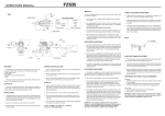
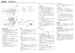
Fig.1
SPECIFICATIONS
45
35.2
Crank Case
Bore
Stroke
Weight (engine)
(muffler)
Practical RPM
48
27.7mm
19.0mm
455g
33g
2,000-15,000rpm
4.
87
Check Valve
97.4
Low Speed Nedle Valve
Tube (A)
Tube (B)
Fuel Filter
FEATURES
PROPELLER INSTALLATION
The FZ70S is the most powerful 4 cycle engine of its size and was developed for sport flying as well as power demanding acrobatics.
• Supercharged system
• Fuel injected
• Regulated and pressurized fuel system
• Muffler
Due to the high torque of the FZ70S engine, we have equipped it with a
double lock system for safety.
The pressurized fuel and injection system makes throttle response superior and is unaffected by tank level.
GLOW PLUG
1. Mount the propeller and tighten the rear nut. Next, tighten the front nut as shown in Fig.1.
2. Select a good quality propeller that will turn in the 9,000 to 12,000 rpm range. We recommend sizes 12x8, 13x7.
START UP
Select the most appropriate plug from those designed specifically for 4
cycle engines. Glow plug selection greatly affects the maximum engine
output and low idle. We recommend the YS #4.
1. Remove tube B from the filter: remove tube A from the check valve,
then fill the tank. (CAUTION: If tank is filled or under pressure re
move tube A first, then tube B. Fuel will eject if tube B is removed while the tank is pressurized. )
INSTALLATION
2.
Open the needle valve 2 turns from the fully closed position.
l.
3.
Open the throttle about 10% from the idle position ( not fully ). And turn the propeller 10 times. This primes sending fuel to the carbure
tor.
2. Always use a fuel filter. We recommend the YS fuel filter.
4.
Close the throttle to the idle position and connect the glow plug bat tery. The engine is now ready for starting.
3.
DO NOT ATTEMPT TO START FULL THROTTLE,
AS THIS IS VERY DANGEROUS.
Connect the engine to the tank as shown in fig.1. Since high pres
sure is applied to the tank, tighten all connections carefully. Care must be taken to prevent pressure leakage due to under tightening of the check valve or by kinking the fuel lines.
Match the direction of the check valve arrow fig.1 with the arrow fac
ing to wards the tank.
l. Use the same size (or slightly smaller) propeller than you intend to
use in flying.
Use a good quality fuel which contains 15-30% nitromethane and oil content of 20-24%. Synthetic or castor oil can be used, or a combina
tion of synthetic and castor.
Do not use four cycle fuel due to low oil content.
3. The needle valve should be set so that the engine is running at a rich setting. Run the engine approximately 20 minutes with this setting.
High Speed Needle Valve
Rear nut
To maximize engine performance and increase durability, please follow
this break-in procedure:
2.
20
Front Nut
BREAK IN
Mount the engine to the model and fly ten times with this setting. This concludes the break-in procedure, it is advisable to always use a slightly rich setting to keep the moving parts lubricated, even after the break-in period .
TAPPET CLEARANCE ADJUSTMENT
1. Tappet clearance is factory preset. No adjustment is necessary until after 1 hour of operation (including break-in period).
2. Clearance adjustment should be done when the engine is cool.
When the engine temperature is high, clearance is higher due to thermal expansion.
3. The proper clearance setting should be at 0 - 0.1mm.
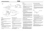
The adjustment is achieved by loosening the locknut (fig.2) and turning the adjusting screw. Tighten the locknut after the adjustment is achieved. Alter the initial 1 hour adjustment, this procedure should be performed a few every 2 hours of use.
Fig.2
0 - 0.1mm
HIGH SPEED ADJUSTMENT
1. Adjustment of high speed is done by the carburetor needle valve.
When the needle valve is turned clockwise, the mixture is leaner.
When it is turned counterclockwise, the mixture is richer. A good starting position for the high speed needle valve is 2 turns open from the fully closed position.
2.
When the engine is started, open the throttle gradually. Next, find the peak position (highest RPM) by adjusting the needle valve. Then the needle valve should be opened approximately 1/8 of a turn from full RPM to achieve best performance. The engine may stop if the throttle is opened to full immediately after starting. Wait until the en
gine temperature rises and then open the throttle slowly .
3. For flying, it is advisable to use a slightly richer mixture setting. By using a richer mixture, the engine temperature is maintained and RPM stability improves.
LOW SPEED ADJUSTMENT
CAM GEAR TIMING ADJUSTMENT
If for some reason you have to disassemble your engine, please follow these important steps on reassembling the cam gear.
1. Remove the carburetor and backplate assembly. Notice the impres
sion made on the crankshaft counterweight. Position it directly straight down or in line with the case outer seam line.
This engine is equipped with a new low speed needle valve to adjust
the mixture from low to mid throttle. This needle valve is located on the
side of the throttle barrel opposite the throttle arm (Fig.1).
2.
1. Open the low speed needle to 1 turns from fully closed position.
DIAPHRAGM AND CHECK VALVE DISASSEMBLY
2.
The low speed needle valve should be set after the high speed nee
dle valve has been adjusted. Close the throttle gradually to a idle
(approximately 2500rpm). Let it idle for 20 to 30 seconds and then slowly advance the throttle. The adjustment is satisfactory at low speed if transition is smooth at this time.
Diaphragm
1. Remove the adjustment screw of the valve, and then remove the inside valve and spring.
2. Clean the inside with alcohol or appropriate cleaner. Reassemble.
3. Screw in the regulator screw until flush with the diaphragm body.
3.
If the engine is running rough on idle, the low speed mixture is rich.
If the engine starts to speed up and dies on idle or starts to detonate, when advancing the throttle, the mixture is lean. Turn the low speed needle valve clockwise to richen and counterclockwise for a leaner mixture (note that the direction of the low speed needle valve is
opposite the high speed needle valve). Adjustments to the low speed needle valve should be 1/8 to 1/4 of a turn increment at a time to achieve smooth throttle response.
Check valve
1. Open the valve by rotating the body counterclockwise.
2. Reassemble the check valve carefully.
IMPORTANT!
The regulator adjusting screw on this engine is factory set. No further
adjustments are necessary. If for some reason you have to disassemble
the regulator assembly, the regulator adjusting screw should be set flush
with the regulator body.
When reinstalling the cam gear, the side with a point mark should befacing the opening of the gear box. Note that it should also be mounted with the point mark located towards the top of the engine just below the cam followers.
IMPORTANT!
Silicone rubber is used in many parts of the YS engine. Use only glow
fuel or methanol for cleaning. Gasoline and other volatile solutions will
damage the silicone if used.
NO.
PARTS# DESCRIPTION
1
G1001
2
G1002
G1002S
Crankcase
Cylinder head assembly
1
Exhaust valve
1
F5103
Intake valve
5
F5105
Valve spring set
4
6
7
8
9
10
11
12
13
14
15
16
17
18
19
20
21
22
23
24
25
26
27
28
29
30
31
32
33
34
35
36
37
38
39
40
41
42
43
44
F5104
F9106
F9107
Spring retainer set
Valve spring clips
F3108
Cylinder head gasket
F5111
Valve cover
F5110
F5112
F5113
F5114
F5115
G1015
G1016
G1017
F5118
F5119
F5120
F5121
F1266
F2267
G1024
G1025
F6126
G1027
F5128
F1213
F1214
F5131
F5132
F1217
F5134
F5135
F5136
F5137
F5138
F5139
F5140
G1041
F5142
G1043
G1044A
G1044
Head bolt set
Valve cover gasket
Valve cover screws
Intake pipe
Intake pipe O rings
Crankshaft
Crankshaft ring
Rear bearing
Front bearing
Front bearing seal
Drive washer
Drive washer retainer
Prop washer
Prop nut set
Piston
Piston ring
Wrist pin
Wrist pin retainers
Rocker arm set
Valve adjuster set
Adjuster nut set
Rocker arm set
Rocker arm screw
E ring clip set
Cam
Cam cover
Cam cover O ring
Cam cover screws
Cam bearing set
Cam follower set
Push rod set
Push rod cover set
Push rod cover O rings
Con rod
Back plate assembly
G1047
Disc valve set screw
49
50
51
52
53
54
55
56
57
F5149
F5150
G1051
G1052
F5153
R6124
F1260S
F1258
F1259
G1057S
F5158
Back plate gasket
Back plate screws
Carburetor body
Throttle barrel
Throttle barrel O ring
THrottle barrel retainer
Throttle arm set
Throttle stop screw
Throttle stop spring
Needle valve set
G1060
Needle socket O ring
61
62
63
64
65
66
F1557
Needle detent
F5186
Low speed needle
F5164
Carburetor gasket
F5187
F5165
G1066A
S1036
Low speed needle O ring
Carburetor screws
Regulator assembly
S1041
Regulator valve O ring
71
72
73
74
75
G1070
G1071
G1072
F5173S
F5173A
F5174
F5175
Regulator body B
Regulator set screws
Regulator spacer
Muffler set
1
1
1
1
1
2
2
2
1
1
O ring set
Gasket set
75
28
9
69
13
71
14
DETAIL A
14
2
30
55
29
28
30
74
54
75
9
1
1
2
4
2
65
29
3
40
2
47
31
42
1
51
64
25
2
2
4
26
1
1
1
2
42
1
39
1
50
27
44
45
27
8
48
43
46
1
16
1
1
1
37
35
36
1
53
63
49
24
41
1
1
65
56
33
2
52
62
72
A
60
59
61
15
38
2
34
1
1
1
58
57
17
38
19
1
1
4
1
1
21
1
2
1
2
G1081
6
2
Rock nuts
Check valve
33
1
1
68
66
5
1
1
Exhaust pipe
32
1
Muffler assembly
F1272
G1080
1
1
69
70
1
2
67
7
2
Regulator valve
Diaphram
S1039
1
1
S1038
11
2
Regulator body A
67
68
1
1
60
70
1
Needle socket
Needle valve O ring
G1059
4
1
F1546
10
73
1
Needle valve
58
59
4
1
47
48
2
Disc valve pin
Disc valve
G1046
2
1
G1045
Strict quality control is implemented by our factory in all phases,
from parts manufactiring to final assembly.
If performance deteriorates or a part fails within one year of
purchase due to a manufacturing error,YS will repair or replace the
engine at no charge. Warranty will not cover normal wear.
Should the engine be modified, incorrectly assembled or abused,
there will be a normal charge for parts and labor. The use of four
cycle fuel due to low oil content will also void warranty.
12
1
Back plate
45
46
1
Cylinder head
3
WARRANTY
QTY
1
1
3
13
23
22
18
20
YAMADA MFG.CO.,LTD
67 Tsuchitori Inuyama Aichi 484-0917 JAPAN
tel 81-568-67-0265
[email protected]