1
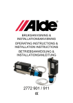
Bruksanvisning & Installationsanvisning OPERATING INSTRUCTIONS & INSTALLATION INSTRUCTIONS betriebsanweisung & INSTALLATIONsanleitung 2772 SE 1 3 Kopplingsschema 230 V ~ för 2772 901/911 Avfasade sidan på styrkabeln B C vid inkoppling till rumstermostat 2772 310 A Rumstermostat 2772 310 (utan lock) Anslutningsplint 12V DC till elpatron 6 5 4 3 2 1 Röd Grå Blå Svart Gul 6 5 4 3 2 1 2000W 1000W Pump Minus +12V DC Flödesriktning 4 Elschema 230 V ~ för elpatron 2772 901/921 2 Manövrering relä 12 V Relä 1050 W B Temperaturbegränsare Drift- Motor 230 V ~ termostat 1050 W C Avfasade sidan på styrkabeln A 5 Elschema 230 V ~ för elpatron 2772 911 1050 W Denna anvisning tar upp installation och montering av Aldes elpatron. Elpatronen är avsedd för invändig montering i husvagn, husbil eller fritidsbåt Den är uppbyggd av ett rostfritt rör med 2 st rostfria elelement inuti. En 230 V cirkulationspump monterad i ena ändan (ej 2772 911). Ett tvåpoligt överhettningsskydd (110°C) och en driftstermostat (80°C) som reglerar vätsketemperaturen i elpatronen är fastskruvade i kopplingsboxen på rörets långsida. Elpatronen är avsedd för montering i ett öppet system med expansionskärl. OBS! Tänk på att läsa bruksanvisningen noggrant för att på ett säkert sätt kunna använda och bruka elpatronen. Personer med begränsad fysisk eller mental förmåga (inklusive barn) får inte använda apparaten utan instruktioner om hur den används på ett säkert sätt. Barn skall hållas under uppsikt så att de ej leker med apparaten. 2 Temperaturbegränsare Drift- 230 V ~ termostat 1050 W OM ELPATRONEN. Manövrering relä 12 V Relä 6 Elschema till rumstermostat 2772 310 ON OFF 0+ OFF 6 5 4 blå grå röd 2 3 1 +12V DC (gul) GND TEKNISK DATA. Längd: Höjd: Bredd: Vikt: Märkspänning: Elementeffekt: Motoreffekt: Anslutningsrör: Vätskevolym: Max radiatortryck: 400 mm (290 utan motor) 150 mm 90 mm 2,3 kg (1,8 kg utan motor) 230 V ~ 2100 W (2 x 1050 W) 25 W Ø 22 mm 0,8 liter 0,05 MPa ( 0,5 bar) SE Elpatron typ 2772 901 Monteras vertikalt/horisontellt i värmesystemet. Inkl cirkulationspump, rumstermostat och fäste. Elpatron typ 2772 911 Monteras vertikalt/horisontellt i värmesystemet eller vertikalt på alla Alde Comfortpannor, oberoende av årsmodell. Inkl gummianslutning, kabel och fäste. Utan cirkulationspump. Elpatron typ 2772 921 Monteras vertikalt/horisontellt i värmesystemet eller vertikalt på alla Alde Comfortpannor, oberoende av årsmodell. Inkl gummianslutning, kabel, fäste och cirkulationspump. Monteringsanvisning. Utrymmet där elpatronen är placerad skall vara torrt. Det skall vara minst 10 mm fritt mellan elpatronen och närliggande inredningsdel eller annan brännbar del. Elpatronen skall vara placerad så att textilier, vätska eller dylikt ej kan komma i kontakt med elpatronen. Elpatron som monteras i båt skall placeras i ett torrt utrymme under däck. All annan placering skall ske i ett IP55 klassat utrymme. Vid eftermontering av elpatron, töm först värmesystemet på glykolvätska och kontrollera att ett jordat uttag för 230 volt är monterat inom räckhåll för elpatronens anslutningssladd. I annat fall måste behörig installatör utföra elinstallationen. Kapa rörledningen ca 350 mm där elpatronen skall monteras. Mellan elpatron och rörledning användes gummiförbindningar av specialgummi, som skall vara fastspända med klämmor. Mellan gummiförbindning och rör bör ett tunt lager av Loctite 5923 appliceras på skarvarna som tätningsmedel. El patron 2772 911 är förberedd för eftermontering av 230 V cirkulationspump. Töm först värmesystemet på glykolvätska. Locket för pumphuset demonteras, därefter monteras cirkulationspump och anslutningskabel (art nr för komplett monteringsats 2772 261) Vid horisontell montering eller där eventuell luftficka kan bildas, skall en luftskruv monteras direkt på ingående rör (se fig 1). OBS! Horisontellt monterade elpatroner får ej monteras så att anslutningsrören går ut åt sidan. Inlopp (fig 1a och 2a) respektive utlopp (fig 1b och 2b), se flödesriktning på pumphus. Elpatronen är utrustad med överhettningsskydd. Detta löser ut när värmesystemet blivit överhettat. För att återställa överhettningsskyddet, tryck på återställningsknappen. Montera elpatronen så det går att komma åt återställningsknappen för överhettningsskyddet (fig 1c och 2c). Elpatronen monteras på fästkonsol som ingår i separat monteringssats eller på Comfortpannans fäste (fig 2). Elinstallation. 12 V DC För att elpatronen skall fungera måste 12 volts styrkretsen kopplas in. Styrkabel ansluts mellan elpatronens anslutningsplint och rumstermostat eller till Comfortpannans anslutningsplint. Obs! Den avfasade sidan på styrkabeln skall monteras mot täckkåpans övre del. På alla Alde Comfortpannor (ej typ 2920) skall förmonterad anslutningsplint klippas av och adapterkabel 2772 170 användas, se fig 2. Val av elpatronens effekt och cirkulationspump sker antingen på Comfortpannans manöverpanel eller på en lös manöverpanel (art nr 2772 310) som monteras i inredningen. Vid inkoppling av elpatron till manöverpanel 2772 310 se fig 3. OBS! Elledningar får ej läggas intill eller på elpatronens värmedelar. 230 V ~ Elpatronen skall alltid anslutas till ett 230 V jordat uttag. Fast installation av vägguttag till 230 V skall utföras av behörig elinstallatör enligt gällande föreskrifter. VARNING! 230 V skall vara väl skilt från 12 V. Fyllning av värmesystemet. Värmesystemet skall fyllas med blandnind av vatten och glykol. Använd helst färdigblandad glykol av hög kvalite (med inhibitorer) för värmesystem av aluminium. Vid användning av koncentrerad glykol skall blandningen bestå 60 % vatten och 40% glykol. Om värmeanläggningen utsätts för lägre temperatur än -25 °C skall glykolhalten höjas, dock ej över 50 %. Påfyllningen sker på gasolpannans expansionskärl (se pannans bruksanvisning). Lufta ock kontrollera vätskenivån i ett nyfyllt värmesystem efter några dagar efter att systemet tagits i bruk. OBS! låt aldrig värmesystemet stå tomt på vätska. Bruksanvisning. Med omkopplaren på manöverpanelen väljs elpatronens effekt, 1 kW eller 2 kW (art nr 2772 310). På Comfortpannan väljs med omkopplare om 12 V eller 230 V cirkulationspump (ej 2772 911) skall användas. För utförligare användning på olika manöverpaneler, se gasolpannans bruksanvisning. VIKTIGT. Elpatronen får ej startas utan vätska. Om elpatron med cirkulationspump är monterad bak på Comfortpanna, får ej pumpen startas förrän all luft är borta. Kontrollera regelbundet anslutningssladden så att inga tecken på skada eller åldring har skett. Skadad sladd skall omedelbart bytas. Kontrollera även att jordförbindelse finns mellan jordade eluttaget och elpatronen. Vid användning av 230 V cirkulationspump rekommenderas kontinuerlig drift för maximal livslängd. Garanti. Aldes garanti gäller ett år från leveransdatum och omfattar endast material- eller fabrikationsfel, förutsatt att denna anvisning har följts. OBS! Endast originaldelar från Alde får användas som reservdel. 3 GB 1 3 Circuit diagram 230V ~ for 2772 901/911 The chamfered side of the control cable B C for connection to thermostat 2772 310 A Thermostat 2772 310 (without cover) 6 5 4 3 2 1 Red Grey Blue Black Yellow Terminal block 12v DC to electrical heating cartridge 6 5 4 3 2 1 2000W 1000W Pump Minus +12V DC Flow direction 4 Electrical diagram 230V ~ for electrical 2 heating cartridge 2772 901 1050 W B Motor Relay Operational relay 12 V Temperature limiter Operating 230 V ~ thermostat 1050 W C The chamfered side of the control cable A 5 Electrical diagram 230V ~ for electrical heating cartridge 2772 911 1050 W Relay Operational relay 12 V Temperature limiter Operating 230 V ~ thermostat 1050 W 6 Electric diagram for room thermostat 2772 310 ON THE ELECTRICAL HEATING CARTRIDGE. These instructions deal with installation and assembly of Alde’s electrical heating cartridge. The electrical heating cartridge is intended for internal assembly in caravan, camper or leisure boat. It is constructed of a stainless steel pipe with 2 stainless steel electrical elements inside. A 230V circulation pump mounted at one end (not 2772 911). A bipolar overheating protection (110°C) and an operating thermostat (80° C), which regulates the temperature of the fluid in the electrical heating cartridge, is mounted to the connection box on the long side of the pipe. The electrical heating cartridge is intended for mounting in an open vented system with expansion vessel. NB! Remember to read the instructions for use carefully in order to be able to use the electrical heating cartridge correctly. Persons with limited physical or mental ability (including children) may not use the apparatus without instruction as to how to do this safely. Children should be kept supervised so that they do not play with the apparatus. 4 OFF 0+ OFF 6 5 4 blue grey red 2 3 1 +12V DC (yellow) GND TECHNICAL DATA. Length: Height: Width: Weight: Rated voltage: Element power: Motor power: Connection pipes: Volume of liquid: Max radiator pressure: 400 mm (290 without motor) 150 mm 90 mm 2,3 kg (1,8 kg without motor) 230 V ~ 2100 W (2 x 1050 W) 25 W Ø 22 mm 0,8 liter 0,05 MPa ( 0,5 bar) GB Electrical heating cartridge type 2772 901 Shall be assembled vertically/horizontally in the heating system. Incl. circulation pump, room thermostat and bracket. Electrical heating cartridge type 2772 911 Shall be assembled vertically/horizontally in the heating system, or vertically on all Alde Comfort boilers, irrespective of year of manufacture. Including rubber connection, cable and bracket. Without circulation pump. Electrical heating cartridge type 2772 921 Shall be assembled vertically/horizontally in the heating system, or vertically on all Alde Comfort boilers, irrespective of year of manufacture. Including rubber connection, cable, bracket and circulation pump. ASSEMBLY INSTRUCTIONS. The space where the electrical heating cartridge is located shall be dry. There shall be at least 10 mm free space between the electrical heating cartridge and adjacent furnishing or other inflammable items. The electrical heating cartridge shall be located so that textiles, liquids and similar cannot come into contact with the electrical heating cartridge. An electrical heating cartridge mounted in a boat shall be located in a dry area below deck. All other locations shall be in an IP55-classed area. When subsequently installing an electrical heating cartridge, first empty the heating system of glycol mixture and check that there is an earthed socket for 230 volts mounted within reach of the electrical heating cartridge’s connection cord. Otherwise, a qualified electrician shall carry out the installation. Cut the pipe about 350 mm where the electrical heating cartridge is to be mounted. Between the electrical heating cartridge and the pipe, a rubber connection of special rubber is used and this shall be clamped tight with clamps. Between the rubber connection and the pipe, a thin layer of Loctite 5023 shall be applied to the joints as sealing agent. Electrical heating cartridge 2772 911 is intended for subsequent assembly of 230V circulation pump. First of all, empty the glycol mixture from the heating system. Dismount the cover from the pump casing, after that, mount the circulation pump and connection cable (the article no. of complete assembly set is 2772 261) With horizontal assembly, or where an air pocket could form, a bleeder screw shall be mounted direct on the incoming pipe (see fig. 1). NB! Electrical heating cartridges mounted horizontally must not be mounted so that the connection pipes extend sideways. Inlet (fig 1a and 2a) and outlet (fig 2b and 2b) respectively, see flow direction on pump housing. The electric cartridge is equipped with an overheating protection. This is triggered when the heating system becomes overheated. Press the resetting button to reset the overheating protection. Fit the electric cartridge so that access to the resetting button of the overheating protection is possible. (fig. 1c and 2c). The electrical heating cartridge shall be mounted on a fixed bracket which is part of a separate assembly set or on the Comfort boiler’s attachment (fig 2). ELECTRICAL INSTALLATION. A control cable is connected between the terminal block of the electrical heating cartridge and thermostat, or to the Comfort boiler’s terminal block. N.B. The chamfered side of the control cable shall be mounted against the upper part of the casing. On all Alde Comfort boilers (not type 2920), the pre-mounted terminal block shall be cut off and adapter cable 2772 170 used, see fig. 2. The power of the electrical heating cartridge and the circulation pump are selected either on the Comfort boiler’s control panel or on a separate control panel (art. no. 2772 310) mounted in the fixtures. For connection of the electrical cartridge to the control panel 2772 310, see fig. 3. NB! Electrical cables must not be located next to or on the warm parts of the electrical heating cartridge. 230 V ~ The electrical heating cartridge shall always be connected to 230V earthed socket. Installation of a fixed 230V wall socket shall be carried out by a qualified electrical engineer in accordance with relevant regulations. WARNING! 230V shall be separate from 12V. FILLING THE HEATING SYSTEM. The heating system shall be filled with a mixture of water and glycol. Preferably use ready-mixed glycol of high quality (with inhibitor) for aluminium heating systems. When using concentrated glycol, the mixture shall consist of 60% water and 40% glycol. If the heating unit is subjected to lower temperatures than -25 °C, the glycol content shall be increased, but not to more than 50%. Top up in the LPG boiler’s expansion vessel (see the boiler’s instructions for use). Bleed and check the fluid level in a newly filled heating system after some days, or after the system has been operating. NB! Never allow the heating system to be standing empty of liquid. INSTRUCTIONS FOR USE. The power is selected with the changeover switch on the control panel, 1kW or 2kW (art. no. 2772 310). On the Comfort boiler, use changeover switch to select whether the12V or 230V circulation pump (not 2772 911) shall be used. For more detailed use of different control panels, see the instructions for use for the LPG boiler. IMPORTANT. The electrical heating cartridge must not be started without liquid. If an electrical heating cartridge with circulation pump is mounted on the back of a Comfort boiler, the pump must not be started until all the air has been bled out. Regularly check the connection cord for any indication of damage or ageing. A damaged cord must be replaced immediately. Also check that there is an earth connection between the earthed power point and the electrical heating cartridge. When using the 230V circulation pump, continual operation is recommended for maximum life. WARRANTY. Alde’s warranty applies for one year from date of delivery, and only covers materials or manufacturing faults, provided that these instructions have been followed. NB! Only use genuine parts from Alde as spare parts. 12 V DC In order for the electrical heating cartridge to function, a 12-volt control circuit must be connected in. 5 DE 1 3 Schaltplan 230 V ~ für 2772 901/911 beim Abgeschrägte Seite des Lenkkabels B C Anschluss zum Raumthermostat 2772 310 A aumthermostat 2772 310 (ohne Gehäusedeckel) Anschlussklemme 12V Gleichstrom zur Elektropatrone 6 5 4 3 2 1 Rot Grau Blau Schwarz Gelb 6 5 4 3 2 1 2000W 1000W Pump Minus +12V Gleichstrom Ablaufrichtung 4 Schaltplan 230 V ~ für Elektropatrone 2 2772 901 B Relais Steuerrelais 12 V 1050 W Motor Temperaturbegrenzer Betriebs- 230 V ~ thermostat 1050 W C Abgeschrägte Seite des Lenkkabels 5 Schaltplan 230 V ~ für Elektropatrone 2772 911 Relais 1050 W A DIE ELEKTROPATRONE. Diese Anleitung behandelt die Installation und die Montage der Elektropatrone von Alde. Die Elektropatrone ist für die innenseitige Montage in Wohnwagen, Wohnmobilen oder Freizeitbooten. Sie besteht aus einer rostfreien Röhre, die 2 rostfreie Elektroheizkörper enthält. An dem einen Ende ist eine 230 V-Umwälzpumpe angebracht (nicht 2772 911). Ein zweipoliger Überhitzungsschutz (110°C) und ein Betriebsthermostat (80°C), das die Flüssigkeitstemperatur in der Elektropatrone regelt, sind an der Schaltbox an der Längsseite der Röhre festgeschraubt. Die Elektropatrone ist für die Montage in einem offenen System mit Expansionsgefäß vorgesehen. ACHTUNG! Lesen Sie die Gebrauchsanleitung sorgfältig durch, um die Elektropatrone sicher anwenden zu können. Personen mit begrenzten physischen oder mentalen Fähigkeiten (einschl. Kinder) dürfen das Gerät nicht ohne Anweisungen zur sicheren Funktion anwenden. Kinder müssen unter Aufsicht stehen, damit sie nicht mit dem Gerät spielen. 6 Steuerrelais 12 V Temperaturbegrenzer Betriebs- 230 V ~ thermostat 1050 W 6 Electroschema für Raumthermostat 2772 310 ON OFF 0+ OFF 6 5 4 blau grau rot 2 3 1 +12V DC (gelb) GND TECHNISCHE DATEN. Länge: Höhe: Breite: Gewicht: Nennspannung: Heizkörperleistung: Motorleistung: Anschlussröhre: Flüssigkeitsvolumen: Max. Radiatordruck: 400 mm (290 ohne motor) 150 mm 90 mm 2,3 kg (1,8 kg ohne motor) 230 V ~ 2100 W (2 x 1050 W) 25 W Ø 22 mm 0,8 liter 0,05 MPa ( 0,5 bar) DE Elektropatrone Typ 2772 901 Vertikale/horizontale Montage in der Heizanlage Einschl. Umwälzpumpe, Raumthermostat und Befestigung. Elektropatrone Typ 2772 911 Vertikale/horizontale Montage in der Heizanlage oder vertikal an allen Alde Comfort-Heizgeräten, unabhängig von Baujahr. Einschl. Gummianschluss, Kabel und Befestigung. Ohne Umwälzpumpe. Elektropatrone Typ 2772 921 Vertikale/horizontale Montage in der Heizanlage oder vertikal an allen Alde Comfort-Heizgeräten, unabhängig von Baujahr. Einschl. Gummianschluss, Kabel, Befestigung und Umwälzpumpe. Montageanweisung. Die Stelle, an der die Elektropatrone angebracht wird, muss trocken sein. Der Abstand zwischen Elektropatrone und dem nächstgelegenen Bauteil oder einem anderen brennbaren Teil hat mindestens 10 mm zu betragen. Die Elektropatrone ist so zu platzieren, dass keine Textilien, Flüssigkeiten und dergleichen mit ihr in Kontakt kommen können. Eine Elektropatrone, die in einem Boot eingebaut werden soll, muss an einer trockenen Stelle unter Deck platziert werden. Alle sonstigen Platzierungen müssen der IP55-Norm entsprechen. Bei Nachmontage der Elektropatrone zunächst die Glykolflüssigkeit aus der Heizanlage ablassen und kontrollieren, dass sich in Reichweite des Anschlusskabels der Elektropatrone ein geerdeter 230VAnschluss befindet. Anderenfalls muss die elektrische Installation von einem autorisierten Installateur vor-genommen werden. Wo die Elektropatrone montiert werden soll, die Rohrleitungen auf etwa 350 mm kappen. Zwischen Elektropatrone und Rohrleitung sind Gummiverbindungen aus Spezialgummi zu verwenden, die mit Metallklemmen befestigt werden. Als Dichtungsmittel zwischen Gummiverbindung und Rohr empfiehlt sich die Verwendung einer dünnen Schicht Loctite 5923. Die Elektropatrone 2772 911 ist zur Nachmontage der 230 V-Umwälzpumpe vorbereitet. Lassen Sie aus der Heizanlage zuerst die Glykolflüssigkeit ab. Der Deckel des Pumpengehäuses wird abmontiert, danach die Umwälzpumpe und das Anschlusskabel montiert (Art.nr. für den kompletten Montagesatz 2772 261) Bei horizontaler Montage oder dort, wo sich eventuelle Luftsäcke bilden können, ist eine Entlüftungsschraube direkt an der Eingangsröhre anzubringen (siehe Abb. 1). ACHTUNG! Horizontal montierte Elektropatronen dürfen nicht so befestigt werden, dass das Anschlussrohr auf die Seite kommt. Einlauf (Abb.1a und 1b) bzw. Auslauf (Abb.1b und 1c), sehen Sie die Flussrichtung auf dem Pumpengehäuse. Die Elektropatrone ist mit einem Überhitzungsschutz ausgestattet. Dieser wird ausgelöst, wenn das Heizsystem überhitzt worden ist. Drücken Sie auf den Rückstellknopf, um den Überhitzungsschutz zu wiederherstellen. Die Elektropatrone soll so montiert werden, dass es möglich wird, den Rückstellknopf des Überhitzungsschutzes zu erreichen. (Abb.1c und 2 c) Die Elektropatrone in der im separaten Montagesatz enthaltenen Halterungskonsole anbringen oder an die Halterung der ComfortHeizung (Abb. 2). Elektrische Installation. 12 V Gleichstrom Damit die Elektropatrone funktionieren kann, muss der 12 VSteuerkreis eingeschaltet werden. Ein Steuerkabel wird von der Klemmleiste der Elektropatrone zum Raumthermostat oder zur Klemmleiste der Alde-ComfortHeizung angeschlossen. ACHTUNG: Die abgeschrägte Seite des Lenkkabels soll gegen den Oberteil des Deckbleches montiert werden. An allen Alde-Comfort-Heizungen (nicht Typ 2920) ist die vormontierte Klemmleiste zu entfernen und das Adapterkabel 2772 170 anzuwenden, siehe Abb. 2. Die Wahl der Leistung von Elektropatrone und Umwälzpumpe erfolgt entweder über das Bedienungsfeld der AldeComfort-Heizung oder über ein separat zu montierendes Bedienungsfeld (Art.nr. 2772 310). Zum Anschluss der Elektropatrone an das Bedienungsfeld 2772 310 siehe Abb. 3. ACHTUNG! Elektrische Leitungen dürfen auf oder an den Heizteilen der Elektropatrone nicht verlegt werden! 230 V ~ Die Elektropatrone ist stets an einen geerdeten 230 VAnschluss anzuschließen. Feste Installationen von Steckdosen dürfen nur von einem autorisierten Elektroinstallateur gemäß geltenden Bestimmungen vorgenommen werden. WARNUNG! 230 V und 12 V sind deutlich voneinander zu trennen. Füllen der Heizanlage. Die Heizanlage wird mit einer Mischung aus Wasser und Glykol gefüllt. Verwenden Sie nach Möglichkeit fertig gemischtes, hochqualitatives Glykol (mit Inhibitoren) für Heizanlagen aus Aluminium. Bei Verwendung von konzentriertem Glykol muss die Mischung aus 60% Wasser und 40% Glykol bestehen. Falls die Heizanlage Temperaturen unter -25 °C ausgesetzt wird, ist der Glykolgehalt auf max. 50% zu erhöhen. Die Glykolmischung wird in das Expansionsgefäß des Heizgeräts gefüllt (siehe Gebrauchsanweisung der Heizung). Entlüften Sie die Heizanlage und kontrollieren Sie das Flüssigkeitsniveau in einer neu gefüllten Heizanlage einige Tage nach Inbetriebnahme der Anlage. ACHTUNG! Die Heizanlage niemals ohne Flüssigkeit stehen lassen! Gebrauchsanweisung. Mit dem Umschalter am Bedienungsfeld wird die Leistung der Elektropatrone gewählt, 1 kW oder 2 kW (Art.nr. 2772 310). An der Alde-Comfort-Heizung wird mit dem Umschalter gewählt, ob die 12 V- oder die 230 V-Umwälzpumpe (nicht 2772 911) in Betrieb genommen werden soll. Zur ausführlicheren Anwendung bei verschiedenen Bedienungsfeldern, siehe Gebrauchsanweisung der Flüssiggasheizung. WICHTIG. Die Elektropatrone darf nicht ohne Flüssigkeit in Betrieb genommen werden. Falls die Elektropatrone mit der Umwälzpumpe auf der Rückseite eines Alde-Comfort-Heizgerätes angebracht ist, darf die Pumpe erst dann gestartet werden, wenn die Luft ganz entwichen ist. Das Anschlusskabel regelmäßig darauf kontrollieren, ob Anzeichen von Schäden oder Alterung auftreten. Beschädigtes Kabel unverzüglich auswechseln. Ebenfalls kontrollieren, dass eine Erdverbindung vom geerdeten Anschluss bis hin zur Elektropatrone besteht. Bei Anwendung der 230 V-Umwälzpumpe wird Dauer-betrieb empfohlen, um eine maximale Lebensdauer zu gewährleisten. Garantie. Die Garantie von Alde gilt ein Jahr ab Lieferdatum und umfasst ausschließlich Material- oder Fabrikationsfehler unter der Voraussetzung, dass die Anleitung befolgt wurde. ACHTUNG! Als Ersatzteile dürfen nur Originalteile von Alde verwendet werden. 7 V-2772 01 Rev 1029 Alde International Systems AB Postal adress: Visit / delivery adress: Phone: Fax: Box 11066Wrangels Allé 90 Nat. 044 - 712 70Nat. 044 - 718 48 291 11 Färlöv 291 75 Färlöv Int. +46 44 712 70Int. +46 44 718 48 SwedenSweden Webb site: www.alde.se E-mail: [email protected]