1
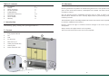
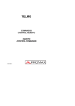
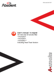
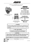
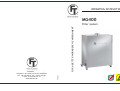
OPERATING INSTRUCTIONS
MG400
Version 1
FILTRONIC
Hissgatan 2, Box 2284, SE-531 02 LIDKÖPING
Tel: +46 510 208 10, Fax: +46 510 201 40
e-mail: [email protected]
www.filtronic.se
FOR A BETTER WORKBENCH ENVIRONMENT
Filter system
Table of contents
1.
2.
3.
4.
5.
6.
7.
8.
9.
10. Warranty
Introduction
Content
Safety instruction
Put into operation
Troubleshooting
Maintenance and service
Technical data
Article number
Warranty
General conditions according to ORGALIME S 2000.
2
2-3
4
4
5
6-8
9
10
11
Filtronic guarantees the product for manufacturing failures for a time period of two (2)
years on filter units and accessories, consumptions not enclosed. The time is measured
from date of invoice.
Only use genuine Filtronic consumables and spare parts in order to ensure reliable
function and to maintain the unit´s warranty. Repairs must be performed by personnel
trained by Filtronic.
The information given is not binding and does not free the user from his or her responsibility
to check the equipment before using it.
1. Introduction
MG400 is a mobile filter unit for elimination of particles and gases in polluted process air
from soldering, gluing, cleaning, laser, printing processes etc.
Filtronic reserves the right to introduce technical changes in the course of product
development.
2. Content
Always contact the supplier before return a product.
The invoice has to be shown at the time of the complaint.
1.
Inlet pipe (Ø 160 mm)
2.
Lid
1
3
3.
Lock
4.
Pre filter box
5.
Main filter 4 pcs
6.
Outlet pipe (Ø 125 mm)
7.
Control panel
8.
Power intake with fuse
2
3
4
5
7
7
6
8
8
2
11
8. Article number
Control panel
Filter system MG400
Micro/Gas filter, Standard (4 pcs)
Micro/Gas filter, Cleanroom (4 pcs)
Micro/Gas filter, MEK (4 pcs)
Micro/Gas filter, Ammonia (4 pcs)
Micro/Gas filter, Solvents/VOC (4 pcs)
450-1000-ESD
450-2000-ESD
450-2002-ESD
450-2003-ESD
450-2006-ESD
450-2012-ESD
Pre filter (2 pcs)
450-4000
Remote control with cable
Remote control (battery) IR
700-3057-L
700-3058
9.
Push button - decrease
10
10.
LED indicator - low airflow
11.
LED indicator - filter time exceeded
12.
LED indicator - operation
13.
Push button - increase
14.
Intake for remote control
15.
Circuit breaker
5
6
7
8
9
13
12
11
14
10
9
15
Remote control:
16.
Push button - start/stop
17.
Push button - filter monitoring
18.
Push button - decrease
19.
Push button - increase
18
16
10
3
17
19
3. Safety instruction
7. Technical data MG400
The unit must not be exposed to temperatures exceeding 50° C, open flames or condensated
solvents.
Width x height x depth
Switch off the filter unit when changing filter.
4. Put into operation
The best possible gas filtration will be achieved if:
- Process air temperature in the gas filter < 38 °C
- Relative humidity < 60 %
- Gas molecules > 30 g / mol (filtration is better with larger molecules)
- Boiling temperature of gas molecules > 0 °C
NOTE! The unit may dust some from the main filter after transportation.
Make sure the starting of the unit is made in an appropriate room.
Weight
Sound level at 1 meter
Voltage
Effect
Glass tube fuse
Maximum suction capacity
Blower capacity
Micro filter - Separation degree, MPPS
Gas filter - Separation degree
Filter monitoring system
Warranty (excl. filter)
796 x 1016 x 402 mm
(31,3 x 40 x 15,9 inch)
68 kg (150 lb)
<55 dB(A)
115 or 230 Volt
300 Watt
2 x 6,3 AT, 250 V
400 m3/h (235 CFM)
450 m3/h (264 CFM)
>99,95 %
>95 %
Yes
2 years
CE-guidelines
89/336, 2004/108, 2006/95
RoHS
Yes
Connect the suction hose or suction tube at the inlet pipe (1). Connect the power cord.
Connect the remote control (14). Switch on the filter unit (15) and thereafter the remote
control on push button (16).
When delivered the filter monitoring is programmed for normal load of the filter (step 3). If
you want to change the program, press the button for filter monitoring (17).
Step Indication
Hours
1
500
2
1000
3
1500
4
2000
5
2500
6
3000
Application example
Heavy smoke formation, gluing
Inspection, repair (set by delivery)
4
9
5. Troubleshooting
When a new main filter is mounted, the filter
monitoring needs to be set to zero. This can
be done in two different ways.
13
Via the control panel:
Do not modify the filter unit. Repairs must be performed by personnel
trained by Filtronic.
1.
Switch off the circuit breaker (15).
2.
Switch on the circuit breaker (15) at
the same time as the buttons (9) and
(13) are pressed down. A ready signal
sounds and the LED indicators die
down.
15
9
- If the filter unit is out of order, please check:
- the electricity supply is connected in a correct way.
- the fuse 6,3 AT is whole.
- If yellow indicator (11) flashes:
Recommended filter lifetime of main filter is exceeded.
See ”Exchange of main filter” under headline 6 ”Maintenance and service”.
- If red indicator (10) shines and alarm is heard:
Inferior suction capacity.
Switch off the filter unit. Check that pre filter, extraction arm or nozzle not are
covered. Clean extraction arm and nozzle if necessary. Change pre filter if necessary.
See ”Exchange of pre filter” under headline 6 ”Maintenance and service”.
If the alarm remains, change the main filter. See ”Exchange of main filter” under
headline 6 ”Maintenance and service”.
Via the remote control:
1.
Switch off the circuit breaker on the
filter unit (15).
2.
Switch on the circuit breaker on
the filter unit (15) at the same time
as the push buttons (18) and (19) are
pressed down. A ready signal sounds
and the LED indicators die down.
If the alarm not is taken care of, the filter unit will stop within five minutes to protect
against overheating.
The main filter should be changed at least once a year to guarantee the separation degree
on gases. At inspection/repair, appr. seven pre filters are used before changing main filter.
18
8
19
5
6. Maintenance and service
Exchange of pre filter:
1.
Switch off the circuit breaker (15)
2.
Unlock the lid and remove it (2).
3.
Remove the pre filter carefully (20).
4.
Mount the new pre filter.
5.
Replace and lock the lid (2).
20
2
21
4
2
Exchange of main filter:
5
For optimal filter lifetime and filter economy
always change pre filter when changing main
filter.
1.
Switch off the circuit breaker (15)
2.
Unlock the lid and remove it (2).
3.
Remove the pre filter carefully (20).
4.
Loosen the wheel (21) and lift up the
pre filter box (4).
5.
NOTE! The new filter has to be
marked with the date of change (11).
6.
Exchange the four main filters (5).
7.
Replace the pre filter box (4) and
mount the wheel (21).
8.
Mount the new pre filter.
9.
Replace and lock the lid (2).
10.
Set the filter monitoring to zero,
see instruction at page 8.
21
15
22
6
7