1
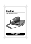
Installation and Operating instructions for
LexCom Home AV Modulator AV110
AV110-1
Configuration of TV-system (PAL-type)
On back, AV110-1 is provided with an aerial input, 1 input for
video composite signals with stereo sound, 1 IR link connection
for the transmission of remote control signals as well as a 12 V DC
output for the supply of a CCTV surveillance camera.
First the TV-system used in the country, where AV110 is installed,
is determined. On the switch block for input 1, contact 7 and 8,
the TV system valid in general for all inputs is selected.
AV 110-1
!"
1
L AUDIO R
VIDEO
RF input
me
Ho
om
C
x
Le
nk
li
AV
AC
12V
LexCom Home
T
OU
IR link
12V DC
OUT
OUT
AV110-1 can convert 1 video signal (composite video) to a RF TV
signal, with mono sound. Moreover, an external RF-signal (120860 Mhz) can be connected and transmitted directly to the
LexCom Home network.
1
1
1
1
4
The video equipment, whose signals you want to distribute in
the LexCom Home “AV link” is connected to the AV input/inputs
on back of AV110.
pcs. Modulator AV110
pcs. Net adapter 230 Volt 50 Hz to 12 Volt AC
pcs. AV cable 3 x phono to 3 x phono, length 1 m
pcs. Unbrako key 2.5 mm
pcs. self-adhesive rubber legs
Please pay attention to the fact that although AV110 has stereo
inputs, the audio signal will be converted to mono sound on the
TV sets connected.
Description of AV110-4 / AV110-1
2 versions of AV modulators are offered, that in their basic
functions are identical. The difference lies mainly in the fact that
they support 1 respectively 4 inputs and relative adjustable
TV-channels. The present instructions are valid for both versions.
AV110 is for dedicated use with in the LexCom Home system
only.
AV110 is a modulator unit that enables the connection of
devices such as VCR machines, DVD players, satellite receivers,
surveillance cameras, PC’s (with TV output) to the “AV link” of
the LexCom Home network, so that the signals from these can be
transmitted to all TV sets connected.
The function implies the installation of a LexCom Home
multimedia amplifier with “AV link” input in the LexCom Home
network.
OUT
LexCom Home
On front, AV110 has a supply plug for a 12V AC net adapter, a
blue light diode indicating normal operation and alarm modes,
a gain adjustment as well as an ”AV link” output jack (RJ45) for
the connection to the LexCom Home network.
AV110-4
On back, AV110-4 is provided with an aerial input, 4 inputs for
video composite signals with stereo sound, as well as 4 “IR link”
connections for the transmission of remote control signals.
When all video sources have been connected (1 source on
AV110-1 / up to 4 sources on AV110-4), the modulators are to be
set to the channels wanted, that at the same time are free in the
programme package of the TV supply (Refer to the following
section setting of TV channels).
Upon setting of AV110, the “AV link” output is to be connected
by means of a shielded patch cord (Cat.6) from the rectangular
RJ45 jack on the front, via the nearest wall outlet to the LexCom
Home network. Cord lengths exceeding 5 m should not be used.
In connection with control of the video sources connected to
AV110, LexCom Home IR system IR110 must be used. IR emitters
are connected to the “IR link” jack on AV110.
Configuration of AV110
The TV-system used must be set for the country in question
(Factory set to : West Europe)
On AV110-4 must be set up to 4 TV channels
On AV110-1 must be set 1 TV channel (in the following called TV
channel).
AV 110-4
AV input
2
4
1
3
Setting of TV channels and general configuration of AV110 is
made on switches located behind the front plate. The 2 Unbrako
screws on front of AV110 are unscrewed by means of the
Unbrako key delivered, and the front plate is removed with care
(in case plugs for the net adapter and output for “AV link” have
been inserted, these are removed first).
Behind the front plate there is a piece of cardboard, which
protects the sensitive electronic parts within AV110.
AV 110-4
Do not remove this cover.
Input 1
Power
input
Power
Gain
adjust
Press
for
signal
Output
network
Channel
select
TVsystem
1 2 3 4 5 6 7 8
O
N
Input 2
Channel
select
N/A
1 2 3 4 5 6 7 8
Input 3
Channel
select
N/A
1 2 3 4 5 6 7 8
Input 4
Channel
select
1 2 3 4 5 6
1 2 3 4 5 6 7 8
1 2 3 4 5 6 7 8
1 2 3 4 5 6 7 8
1 2 3 4 5 6 7 8
O
O
O
CTS 194-8
T614 N CTS 194-8
T614 N CTS 194-8
T614 N CTS 194-8
OUT
L AUDIO R
RF input
VIDEO
L AUDIO R
VIDEO
#$
%
Setting of contact 7 and 8 for TV-system. The setting is made
only on the input 1 switch block in A110-4.
Setting of TV channels:
If possible, an overview of the TV channels connected on the
LexCom Home network should be prepared prior to the setting.
This implies the establishment of an overview of the TV channels
that can be received on the TV sets connected (channels or
frequencies).
Then the free TV channels which you want to use for the video
signals connected to AV110 are selected.
The user may freely select the TV channels dedicated to the AV
inputs, based on the possible settings shown in the channel table
(switch-settings). However, this will be limited by the number
and location of the locally available TV channels in the same
channel area.
Selection of TV channels that have already been taken in the
cable-TV package delivered by an external supplier is not
possible.
l
TV-channels are set by means of the contacts 1-6 in a pattern
corresponding to the TV channel which you want to set for
the AV input in question.
l
Setting of the contacts is made in accordance with the channel
table for the TV-system in question.
l
Contacts can be set using a small screwdriver or the point of a
pencil.
AV110-4 can convert 4 video signals (composite video) to RF TV
signals, with mono sound. Moreover, an external RF-signal (120860 Mhz) can be connected and transmitted directly to the
LexCom Home network using the RF-input.
AV110-4 has been constructed in such a way that none of the
4 channels can be set to the same TV-channel. Moreover,
neighbouring channels to a selected channel cannot be selected.
The reason is to prevent disturbances of the TV-picture due to
interference.
Do not try to remove this cardboard, as the result may be destruction of the unit. If removal or attempted removal of this cardboard can be ascertained, the guarantee will be repealed. The
piece of cardboard contains holes for the various jacks, the light
diode and 4 blue switch blocks (Input 1-4) with white contacts.
Below the white pushbuttons, these are numbered from 1 to 8.
In AV110-4, contact 7 and 8 on input 2, 3 and 4 are NOT used.
AV110-1 contains only 1 switch block (Input 1).
Above the blue switch blocks, the cardboard indicates the AV
input which is set with the switch block in question.
Setting of TV:
On front of the piece of cardboard a point has been indicated
which you may press in order to start a test picture- and sound
generator. When this is active, the blue light diode will flash
constantly with a quick blinking speed. This picture- and sound
signal may be used for the search and setting of the TV channels
(coming from AV110) on the TV-sets.
If you have selected the correct channel on the TV-sets connected, you will see 2 vertical white lines on a black background. At
the same time there will be a 1000Hz tone in the loudspeakers.
The picture- and sound generator is turned off by pressing the
signal button again, or by turning the power to AV110 off and
on.
Due to interference between different channels you may see
disturbed pictures. If this is the case, you may try another
channel combination.
Please bear in mind that change of the channel settings in AV100
will enter into force only when the power to AV110 has been
turned off for 10 seconds and turned on again.
Upon finalisation of setting AV110 and with constant light in the
blue light diode, the plugs on the front are removed again and
the front plate is mounted with care and fastened by means of
the screws delivered.
The output level of the TV picture from AV110 may be adjusted
by means of the Gain screw on front of AV110. Adjustment is
made until the best picture quality is obtained. The following
applies in general:
l
When installing AV110 where the distance to the LexCom
Home distribution centre is long, the level of the signals
must be increased, in order to avoid a TV picture with noise.
l
When installing AV110, where the distance to the LexCom
Home distribution centre is short, the intensity of the signals
must be reduced, in order to avoid oversteering of the TV
picture.
Please note: Due to the radiation of noise it is important that
the front plate be mounted with both screws immediately after
the setting.
Technical specifications
Note:
Pay attention to the fact that no neighbouring channels in AV
110-4 can be selected, as the result may be noise problems on the
channels. In general, the selection of a TV channel immediately
next to another channel is not possible. Consequently, it will not
be possible to get a good result, if you select channel 10, and
there already is a TV station on channel 9 or 11.
Turn-off of channel
If you do not want to use one or several channels, they should
be turned off (disabled) by pressing all white keys down. This
may prove to be very useful, in case there are many TV stations
in the channel area. Then the vacant channels for the video
inputs not in use cannot disturb the existing TV stations.
IR link
OUT
If this is the case, another TV channel for one of the inputs must
be selected. In order to store new settings, the net adapter plug
is pulled out, and after 10 seconds it is put back again.
For each AV input to which a signal source (video composite +
LF audio) has been connected a TV channel must be set.
AV link
12V AC
If the wrong system is selected, this may result in no colours on
the pictures, missing sound or no picture at all.
Installation of AV110:
AV110 includes the following parts:
4 flashes, there is a conflict in the selection of channels between
input 2 and 4. Maybe these have been set on the same channel
or neighbouring channels.
Start-up:
Upon selection of TV-system and setting or turn-off of the
wanted channels, first the RJ45 jack (AV link) for the connection
of AV110 to the LexCom Home network is connected.
Then the 12V AC net adapter is connected. The blue light diode
will turn on.
If the light diode flashes, please note the speed of the flashing. If
for instance there are 2 flashes followed by an interval and then
Power supply
Power consumption
Frequency band
Input sensitivity
Video Input Impedance
Audio Input Impedance
Output level
Output Impedance
Gain attenuation
Modulation
TV System, output
Sound
Extra input (RF)
Operating temperature
BxHxD
Weight
Standards
12V DC output,
AV110-1 only
12V AC
< 6Watt (AV110-4)
< 4Watt (AV110-1)
130 - 670 MHz
0,5 Vpp
75 Ohm, Phono (RCA)
10 kOhm, Phono (RCA)
95 dB µV
100 Ohm, ballanced (RJ45)
Min. 0-20 dB
Double sideband
PAL B/G, L, I and D (selectable)
Mono
75 Ohm, IEC female (120-860 MHz)
0-35 oC
170 x 47 x 165
0,80 kg
EN 55020
EMC-directive 89/336/EEC
max. 200 mA
Channel tables:
To each setting, the TV channel and corresponding frequency (MHz) is stated.
1 2 3 4 5 6 7 8
Off
On
1 2 3 4 5 6 7 8
1 2 3 4 5 6 7 8
Off
S8
154.25 On
Off
S9
161.25 On
S 10 Off
168.25 On
Off
e5
175.25 On
Off
e6
182.25 On
Off
e7
189.25 On
Off
e8
196.25 On
1 2 3 4 5 6 7 8
1 2 3 4 5 6 7 8
1 2 3 4 5 6 7 8
1 2 3 4 5 6 7 8
1 2 3 4 5 6 7 8
1 2 3 4 5 6 7 8
S15
Off
259.25 On
1 2 3 4 5 6 7 8
S16
Off
266.25 On
1 2 3 4 5 6 7 8
S39
447.25
Off
On
S40
455.25
Off
On
S41
463.25
Off
On
Off
On
CH22
479.25
Off
On
Off
On
CH24
495.25
Off
On
CH25
503.25
Off
On
1 2 3 4 5 6 7 8
1 2 3 4 5 6 7 8
S21
Off
303.25 On
1 2 3 4 5 6 7 8
1 2 3 4 5 6 7 8
CH27
519.25
Off
On
CH28
527.25
Off
On
1 2 3 4 5 6 7 8
S22
Off
311.25 On
Off
S40
455.25 On
Off
On
CH45
663.25
Off
On
CH47
679.25
Off
On
Off
CH23
487.25 On
Off
CH24
495.25 On
CH25 Off
503.25 On
Off
L18
On
280.00
1 2 3 4 5 6 7 8
1 2 3 4 5 6 7 8
CH26 Off
511.25 On
Video recorder
DVD
R-13
231.25
RF signals in AV- link
CATV + AV signals
R-14
239.25
Room 2
R-15
247.25
2nd TV
CH34
575.25
Trouble shooting
3UREOHP
5HDVRQ
No AV modulator signals at
all.
CH35
583.25
1 2 3 4 5 6 7 8
CATV + AV signals
R-16
255.25
1 2 3 4 5 6 7 8
Poor picture on AV signal(s).
CH36
591.25
1. Power not connected!
2. Conflicts between selected AV channels causes the AV
modulator to shut down!
3. Wrong patching in the distribution centre!
4. Wrong TV system selected!
5. AV modulator not working / faulty!
1. Output level from the AV modulator is too weak!
2. Wrong TV system selected!
3. AV signals being interfered by other TV channels!
1 2 3 4 5 6 7 8
Off
S-31
383.25 On
CH37
599.25
1 2 3 4 5 6 7 8
Off
S-32
391.25 On
CH38
607.25
Poor sound on AV signal(s).
1 2 3 4 5 6 7 8
S-33
Off
399.25 On
CH39
615.25
1 2 3 4 5 6 7 8
Off
S-34
407.25 On
1 2 3 4 5 6 7 8
I-07
Off
199.25 On
CH33
567.25
S-30
Off
375.25 On
Off
On
CH39
615.25
1 2 3 4 5 6 7 8
1 2 3 4 5 6 7 8
Off
S-29
367.25 On
1 2 3 4 5 6 7 8
I-06
191.25
Sat. Receiver #2
1 2 3 4 5 6 7 8
Off
CH32
559.25 On
S-28
Off
359.25 On
Off
On
1 2 3 4 5 6 7 8
1 2 3 4 5 6 7 8
Off
L19
288.00 On
I-05
183.25
1 2 3 4 5 6 7 8
CH30 Off
543.25 On
Sat. Receiver #1
R-12
223.25
Off
CH31
551.25 On
1 2 3 4 5 6 7 8
1 2 3 4 5 6 7 8
1 2 3 4 5 6 7 8
1 2 3 4 5 6 7 8
Off
L17
272.00 On
S-27
Off
351.25 On
Off
On
Disable
Living room TV
Coaxial cable
1 2 3 4 5 6 7 8
1 2 3 4 5 6 7 8
1 2 3 4 5 6 7 8
I-04
175.25
A110
R-11
215.25
Off
CH30
543.25 On
S-26
Off
343.25 On
Off
On
1 2 3 4 5 6 7 8
1 2 3 4 5 6 7 8
Off
L16
On
264.00
1 2 3 4 5 6 7 8
Switch settings
for UK
1 2 3 4 5 6 7 8
CH38 Off
607.25 On
IR-Rec.
1 2 3 4 5 6 7 8
CH22
479.25
CH46
671.25
Room 1
1 2 3 4 5 6 7 8
1 2 3 4 5 6 7 8
1 2 3 4 5 6 7 8
1 2 3 4 5 6 7 8
1 2 3 4 5 6 7 8
1 2 3 4 5 6 7 8
CH29 Off
535.25 On
1 2 3 4 5 6 7 8
CH45
663.25
1 2 3 4 5 6 7 8
Off
On
1 2 3 4 5 6 7 8
S-25
Off
335.25 On
Disable Off
On
CH21 Off
471.25 On
1 2 3 4 5 6 7 8
CH21 Off
471.25 On
Off
S-33
399.25 On
1 2 3 4 5 6 7 8
CH37 Off
599.25 On
CATV signals
R-10
207.25
Off
CH29
535.25 On
S-24
Off
327.25 On
1 2 3 4 5 6 7 8
1 2 3 4 5 6 7 8
1 2 3 4 5 6 7 8
CH28 Off
527.25 On
Off
S-41
463.25 On
CH44
655.25
CH36
Off
591.25 On
1 2 3 4 5 6 7 8
1 2 3 4 5 6 7 8
1 2 3 4 5 6 7 8
1 2 3 4 5 6 7 8
CH27 Off
519.25 On
Off
S-40
On
455.25
1 2 3 4 5 6 7 8
S-32
Off
391.25 On
1 2 3 4 5 6 7 8
CH28
527.25
S-23
Off
319.25 On
1 2 3 4 5 6 7 8
Off
On
CH27
Off
519.25
On
1 2 3 4 5 6 7 8
1 2 3 4 5 6 7 8
CH46
671.25
1 2 3 4 5 6 7 8
1 2 3 4 5 6 7 8
CH35
Off
583.25 On
1 2 3 4 5 6 7 8
1 2 3 4 5 6 7 8
CH43
647.25
Conseptual Installation
R-09
199.25
CH26 Off
511.25 On
S-22
Off
311.25 On
1 2 3 4 5 6 7 8
1 2 3 4 5 6 7 8
Off
S41
463.25 On
Off
L15
256.00 On
Off
On
CH44
655.25
1 2 3 4 5 6 7 8
Off
S-23
319.25 On
S-24 Off
327.25 On
1 2 3 4 5 6 7 8
1 2 3 4 5 6 7 8
1 2 3 4 5 6 7 8
1 2 3 4 5 6 7 8
1 2 3 4 5 6 7 8
1 2 3 4 5 6 7 8
Off
L-14
248.00 On
1 2 3 4 5 6 7 8
CH26
511.25
Off
S39
447.25 On
Off
L-13
248.00 On
Off
On
1 2 3 4 5 6 7 8
1 2 3 4 5 6 7 8
1 2 3 4 5 6 7 8
1 2 3 4 5 6 7 8
S20
294.25
Off
S38
439.25 On
1 2 3 4 5 6 7 8
CH43
647.25
S-31
Off
383.25 On
1 2 3 4 5 6 7 8
1 2 3 4 5 6 7 8
1 2 3 4 5 6 7 8
1 2 3 4 5 6 7 8
1 2 3 4 5 6 7 8
1 2 3 4 5 6 7 8
Off
L-12
240.00 On
Off
On
1 2 3 4 5 6 7 8
Off
S37
431.25 On
Off
L-11
On
232.00
CH42
639.25
1 2 3 4 5 6 7 8
1 2 3 4 5 6 7 8
Off
L-10
224.00 On
Off
On
R-08
191.25
Off
CH25
503.25 On
Off
S-21
303.25 On
1 2 3 4 5 6 7 8
CH41
631.25
1 2 3 4 5 6 7 8
Off
S-22
On
311.25
Off
CH34
575.25 On
CH26 Off
511.25 On
S-39 Off
447.25 On
CH42
639.25
1 2 3 4 5 6 7 8
1 2 3 4 5 6 7 8
1 2 3 4 5 6 7 8
1 2 3 4 5 6 7 8
S-30
Off
375.25 On
1 2 3 4 5 6 7 8
CH33 Off
567.25 On
CH25 Off
503.25 On
S-38 Off
439.25 On
CH41
631.25
Coaxial cable
1 2 3 4 5 6 7 8
1 2 3 4 5 6 7 8
1 2 3 4 5 6 7 8
1 2 3 4 5 6 7 8
I-19
Off
295.25 On
Off
On
1 2 3 4 5 6 7 8
1 2 3 4 5 6 7 8
R-07
Off
183.25 On
CH24 Off
495.25 On
I-18
Off
287.25 On
1 2 3 4 5 6 7 8
CH40
623.25
Off
S36
423.25 On
Off
L-09
216.00 On
1 2 3 4 5 6 7 8
Off
On
CH23 Off
487.25 On
1 2 3 4 5 6 7 8
1 2 3 4 5 6 7 8
1 2 3 4 5 6 7 8
1 2 3 4 5 6 7 8
1 2 3 4 5 6 7 8
CH23
487.25
CH39
615.25
Off
S35
415.25 On
Off
L-08
208.00 On
1 2 3 4 5 6 7 8
Off
On
Off
On
1 2 3 4 5 6 7 8
1 2 3 4 5 6 7 8
I-17
Off
279.25 On
1 2 3 4 5 6 7 8
R-06
175.25
CH22 Off
479.25 On
I-16
Off
271.25 On
1 2 3 4 5 6 7 8
1 2 3 4 5 6 7 8
1 2 3 4 5 6 7 8
1 2 3 4 5 6 7 8
1 2 3 4 5 6 7 8
CH40
623.25
CH32 Off
559.25 On
CH24 Off
495.25 On
S-37 Off
431.25 On
S-29
Off
367.25 On
S-21 Off
303.25 On
Off
On
1 2 3 4 5 6 7 8
1 2 3 4 5 6 7 8
1 2 3 4 5 6 7 8
Off
R-21
On
295.25
1 2 3 4 5 6 7 8
Disable Off
On
Switch settings
for East Europa
CH21
471.25
I-15
Off
263.25 On
1 2 3 4 5 6 7 8
1 2 3 4 5 6 7 8
1 2 3 4 5 6 7 8
1 2 3 4 5 6 7 8
CH21
471.25
CH38
607.25
Off
S34
407.25 On
Off
L-07
200.00 On
1 2 3 4 5 6 7 8
Off
On
Off
S33
399.25 On
L-06
Off
184.00 On
1 2 3 4 5 6 7 8
1 2 3 4 5 6 7 8
1 2 3 4 5 6 7 8
1 2 3 4 5 6 7 8
1 2 3 4 5 6 7 8
CH37
599.25
Off
S32
391.25 On
1 2 3 4 5 6 7 8
1 2 3 4 5 6 7 8
Off
On
1 2 3 4 5 6 7 8
1 2 3 4 5 6 7 8
1 2 3 4 5 6 7 8
1 2 3 4 5 6 7 8
S19
Off
287.25 On
1 2 3 4 5 6 7 8
Off
On
Off
On
1 2 3 4 5 6 7 8
Off
S18
280.25 On
Off
On
S38
439.25
CH36
591.25
Off
S-41
463.25 On
I-14
Off
255.25 On
1 2 3 4 5 6 7 8
S31
Off
383.25 On
Off
On
1 2 3 4 5 6 7 8
Off
On
1 2 3 4 5 6 7 8
1 2 3 4 5 6 7 8
L-05
Off
176.00 On
Off
On
CH35
583.25
S30
Off
375.25 On
Disable Off
On
1 2 3 4 5 6 7 8
1 2 3 4 5 6 7 8
1 2 3 4 5 6 7 8
1 2 3 4 5 6 7 8
1 2 3 4 5 6 7 8
Off
On
Off
S29
367.25 On
CH38 Off
607.25 On
Off
On
1 2 3 4 5 6 7 8
1 2 3 4 5 6 7 8
1 2 3 4 5 6 7 8
CH34
575.25
1 2 3 4 5 6 7 8
1 2 3 4 5 6 7 8
Switch settings
for France
S37
431.25
Off
S28
359.25 On
CH37 Off
599.25 On
Off
On
1 2 3 4 5 6 7 8
1 2 3 4 5 6 7 8
1 2 3 4 5 6 7 8
1 2 3 4 5 6 7 8
Off
S17
273.25 On
Off
On
Off
On
1 2 3 4 5 6 7 8
1 2 3 4 5 6 7 8
Off
On
S33
399.25
CH33
Off
567.25 On
1 2 3 4 5 6 7 8
1 2 3 4 5 6 7 8
1 2 3 4 5 6 7 8
1 2 3 4 5 6 7 8
1 2 3 4 5 6 7 8
CH31 Off
551.25 On
CH23 Off
487.25 On
S-36 Off
423.25 On
Off
S-28
359.25 On
Off
R-20
287.25 On
CH-46 Off
671.25 On
1 2 3 4 5 6 7 8
1 2 3 4 5 6 7 8
1 2 3 4 5 6 7 8
S-35 Off
415.25 On
Off
S-27
351.25 On
Off
R-19
279.25 On
CH22 Off
479.25 On
1 2 3 4 5 6 7 8
1 2 3 4 5 6 7 8
S-26
Off
343.25 On
1 2 3 4 5 6 7 8
1 2 3 4 5 6 7 8
1 2 3 4 5 6 7 8
S-40
Off
455.25 On
I-13
Off
247.25 On
1 2 3 4 5 6 7 8
Off
S27
351.25 On
CH36 Off
591.25 On
1 2 3 4 5 6 7 8
1 2 3 4 5 6 7 8
S14
Off
252.25 On
Off
On
Off
On
1 2 3 4 5 6 7 8
S13
Off
245.25 On
Off
On
S32
391.25
1 2 3 4 5 6 7 8
1 2 3 4 5 6 7 8
1 2 3 4 5 6 7 8
1 2 3 4 5 6 7 8
S12 Off
238.25 On
Off
On
Off
On
1 2 3 4 5 6 7 8
s11
Off
231.25 On
Off
On
S31
383.25
1 2 3 4 5 6 7 8
Off
CH32
559.25 On
R-18 Off
271.25 On
CH-45 Off
663.25 On
1 2 3 4 5 6 7 8
1 2 3 4 5 6 7 8
1 2 3 4 5 6 7 8
1 2 3 4 5 6 7 8
S-39
Off
447.25 On
I-12
Off
239.25 On
Off
On
1 2 3 4 5 6 7 8
S26
Off
343.25 On
CH35
Off
583.25 On
1 2 3 4 5 6 7 8
1 2 3 4 5 6 7 8
1 2 3 4 5 6 7 8
Off
On
Off
On
S36
423.25
e12 Off
224.25 On
Off
On
S30
375.25
1 2 3 4 5 6 7 8
1 2 3 4 5 6 7 8
1 2 3 4 5 6 7 8
Off
On
Off
On
S35
415.25
e11 Off
217.25 On
Off
On
S29
367.25
CH34 Off
575.25 On
CH31
551.25
Off
On
1 2 3 4 5 6 7 8
1 2 3 4 5 6 7 8
S-34 Off
407.25 On
Off
S-25
335.25 On
R-17 Off
263.25 On
CH-44 Off
655.25 On
1 2 3 4 5 6 7 8
1 2 3 4 5 6 7 8
1 2 3 4 5 6 7 8
CH-43
647.25
1 2 3 4 5 6 7 8
S-38
Off
439.25 On
I-11
Off
231.25 On
Off
CH30
543.25 On
S25
Off
335.25 On
1 2 3 4 5 6 7 8
1 2 3 4 5 6 7 8
1 2 3 4 5 6 7 8
1 2 3 4 5 6 7 8
Off
On
Off
On
S34
407.25
e10
Off
210.25 On
Off
On
S28
359.25
Off
CH33
567.25 On
1 2 3 4 5 6 7 8
1 2 3 4 5 6 7 8
1 2 3 4 5 6 7 8
Off
On
1 2 3 4 5 6 7 8
S-37
Off
413.25 On
I-10
Off
223.25 On
Off
CH29
535.25 On
S24
Off
327.25 On
1 2 3 4 5 6 7 8
1 2 3 4 5 6 7 8
1 2 3 4 5 6 7 8
e9
Off
203.25 On
Off
On
Off
On
1 2 3 4 5 6 7 8
1 2 3 4 5 6 7 8
Off
On
S27
351.25
1 2 3 4 5 6 7 8
1 2 3 4 5 6 7 8
1 2 3 4 5 6 7 8
Off
I-09
215.25 On
CH-42
639.25
1 2 3 4 5 6 7 8
1 2 3 4 5 6 7 8
1 2 3 4 5 6 7 8
1 2 3 4 5 6 7 8
S-36
Off
423.25 On
1 2 3 4 5 6 7 8
1 2 3 4 5 6 7 8
Off
CH28
527.25 On
S23
Off
319.25 On
Off
On
Off
I-08
207.25 On
Off
On
1 2 3 4 5 6 7 8
1 2 3 4 5 6 7 8
CH32
559.25
CH27
519.25
Off
S22
311.25 On
Off
CH31
551.25 On
1 2 3 4 5 6 7 8
1 2 3 4 5 6 7 8
1 2 3 4 5 6 7 8
Off
On
Off
On
1 2 3 4 5 6 7 8
1 2 3 4 5 6 7 8
Off
On
S26
343.25
1 2 3 4 5 6 7 8
1 2 3 4 5 6 7 8
1 2 3 4 5 6 7 8
1 2 3 4 5 6 7 8
Off
On
Off
On
1 2 3 4 5 6 7 8
1 2 3 4 5 6 7 8
Off
On
S25
335.25
Off
S21
303.25 On
CH30 Off
543.25 On
1 2 3 4 5 6 7 8
1 2 3 4 5 6 7 8
1 2 3 4 5 6 7 8
1 2 3 4 5 6 7 8
CH29 Off
535.25 On
1 2 3 4 5 6 7 8
1 2 3 4 5 6 7 8
1 2 3 4 5 6 7 8
Off
On
Off
On
1 2 3 4 5 6 7 8
1 2 3 4 5 6 7 8
Off
On
S24
327.25
1 2 3 4 5 6 7 8
S7
Off
147.25 On
Off
On
Off
On
1 2 3 4 5 6 7 8
S6
Off
140.25 On
Off
On
S23
319.25
1 2 3 4 5 6 7 8
S5
Off
133.25 On
Off
On
1 2 3 4 5 6 7 8
1 2 3 4 5 6 7 8
Off
On
AV-modulator
4 input/ 1 output
Switch settings
for BG Europe
CH40
623.25
1 2 3 4 5 6 7 8
S-35
Off
415.25 On
CH41
631.25
Disturbances on other TV
channels when the AV
modulator is connected.
Test signal disappears from
the TV shortly after being
activated.
4. Poor or broken patch cable between AV modulator and
wall outlet!
5. AV modulator not working properly!
6. R/TV module not working properly!
1. Audio inputs of AV modulator are being over steered!
2. Poor of broken audio interconnection cable between AV
modulator and source!
1. Output level from the AV modulator is too high!
2. The AV signals are interfering with other TV channels!
1. The black and white test picture puts heavy demands on
to the TV’s ability to support the contrasts of the picture!
6ROXWLRQ
1. Connect the power adapter. Check that the power LED indicator lights up permanently.
2. Select a new AV channel for the input indicated by the flashing LED. Refer to relevant
chapter in this installation guide.
3. Check the patch cord connections up to the AV link port on the R/TV amplifier. If AV
combiner used also check these connections.
4. Select right TV system. Refer to relevant chapter in this installation guide.
5. Replace.
1. Increase the gain (output volume) on the AV modulator until a clear picture is obtained.
2. Select the right TV system. Refer to relevant chapter in this installation guide.
3. Select another TV channel to the AV input being interfered. Refer to relevant chapter in
this installation guide.
4. Replace to new one. Use only STP Cat.6 patch cable, max. 5m.
5. Replace.
6. Replace R/TV module.
1. Decrease the output volume from the source connected. Refer to the manual of the
appliance in question.
2. Check the cables and replace if necessary.
1. Reduce the gain (output volume) on the AV modulator until clear TV channels are
obtained. Make sure that the quality of the AV signals is maintained.
2. Select another channel for the AV signal where the interference is gone. Refer to
relevant chapter in this installation guide.
1. Some TV’s are simply unable to show such a test picture. Search for a live picture
instead.
019D8516_01 © LK as 09/2003