Download INSTALLATION MANUAL INSTALLATIONSANLEITUNG
Transcript
INNENGERÄT (Kassettentyp) Nur für autorisiertes Fachpersonal. MANUEL D’INSTALLATION APPAREIL INTÉRIEUR (type cassette) AUXD18GALH AUXD24GALH AUXA30GALH AUXA36GALH AUXA45GALH AUXA54GALH Pour le personnel agréé uniquement. MANUAL DE INSTALACIÓN UNIDAD INTERIOR (Tipo casete) Únicamente para personal de servicio autorizado. MANUALE DI INSTALLAZIONE UNITÀ INTERNA (tipo a cassetta) Deutsch INSTALLATIONSANLEITUNG Français For authorized service personnel only. Español INDOOR UNIT (Cassette Type) Italiano INSTALLATION MANUAL English TM MANUAL DE INSTALAÇÃO UNIDADE INTERIOR (Tipo Cassete) Apenas para técnicos autorizados. РУКОВОДСТВО ПО УСТАНОВКЕ ВНУТРЕННИЙ МОДУЛЬ (кассетного типа) Только для авторизованного обслуживающего персонала. MONTAJ KILAVUZU İÇ ÜNİTE (Kaset Tipi) Português Μόνο για εξουσιοδοτημένο τεχνικό προσωπικό. Русский ΕΣΩΤΕΡΙΚΗ ΜΟΝΑΔΑ (Τύπος Κασέτας) Türkçe ΕΓΧΕΙΡΙΔΙΟ ΕΓΚΑΤΑΣΤΑΣΗΣ Ελληνικά A uso esclusivo del personale tecnico autorizzato. Yalnızca yetkili servis personeli için. PART NO. 9371022260-03 9371022260-03_IM.indb 1 5/29/2013 2:48:30 PM INSTALLATION MANUAL PART NO. 9371022260-03 VRF system indoor unit (Cassette type) Do not attempt to install the air conditioner or a part of the air conditioner by yourself. 1. SAFETY PRECAUTIONS .........................................................................................1 2. ABOUT THIS PRODUCT..........................................................................................1 2.1. Precautions for using the R410A refrigerant ......................................................1 2.2. Special tool for R410A .......................................................................................1 2.3. Accessories .......................................................................................................2 2.4. Optional parts ....................................................................................................2 INSTALLATION WORK ............................................................................................2 3.1. Selecting an installation location .......................................................................2 3.2. Installation dimensions ......................................................................................3 3.3. Installing the unit ................................................................................................3 4. PIPE INSTALLATION ...............................................................................................5 4.1. Selecting the pipe material ................................................................................5 4.2. Pipe requirement ...............................................................................................5 4.3. Flare connection (pipe connection) ...................................................................5 4.4. Installing heat insulation ....................................................................................6 5. INSTALLING DRAIN PIPES .....................................................................................6 6. ELECTRICAL WIRING .............................................................................................7 6.1. Electrical requirement ........................................................................................8 6.2. Wiring method ...................................................................................................8 6.3. Unit wiring ..........................................................................................................8 6.4. Connection of wiring ..........................................................................................9 6.5. External input and external output (Optional parts) ...........................................10 7. This mark indicates procedures which, if improperly performed, might possibly result in personal harm to the user, or damage to property. Read carefully all security information before use or install the air conditioner. CONTENTS 3. CAUTION FIELD SETTING .......................................................................................................12 7.1. Setting the address ............................................................................................12 7.2. Custom code setting ..........................................................................................13 7.3. Switching the upper limit of cooling temperature .................................................. 13 7.4. Function setting .................................................................................................14 8. CASSETTE GRILLE INSTALLATION .......................................................................15 9. TEST RUN ................................................................................................................15 9.1. Test run using Outdoor unit (PCB) .....................................................................15 9.2. Test run using Remote Controller ......................................................................15 10. CHECK LIST.............................................................................................................15 11. ERROR CODES .......................................................................................................15 This unit must be installed by qualified personnel with a capacity certificate for handling refrigerant fluids. Refer to regulation and laws in use on installation place. The installation must be carried out in compliance with regulations in force in the place of installation and the installation instructions of the manufacturer. This unit is part of a set constituting an air conditioner. It must not be installed alone or with non-authorized by the manufacturer. Always use a separate power supply line protected by a circuit breaker operating on all wires with a distance between contact of 3mm for this unit. The unit must be correctly earthed (grounded) and the supply line must be equipped with a differential breaker in order to protect the persons. The units are not explosion proof and therefore should not be installed in explosive atmosphere. Never touch electrical components immediately after the power supply has been turned off. Electric shock may occur. After turning off the power, always wait 5 minutes before touching electrical components. This unit contains no user-serviceable parts. Always consult authorized service personnel to repairs. When moving, consult authorized service personnel for disconnection and installation of the unit. 2. ABOUT THIS PRODUCT 2.1. Precautions for using the R410A refrigerant WARNING Do not introduce any substance other than the prescribed refrigerant into the refrigeration cycle. If air enters the refrigeration cycle, the pressure in the refrigeration cycle will become abnormally high and cause the piping to rupture. If there is a refrigerant leakage, make sure that it does not exceed the concentration limit. If a refrigerant leakage exceeds the concentration limit, it can lead to accidents such as oxygen starvation. Do not touch refrigerant that has leaked from the refrigerant pipe connections or other area. Touching the refrigerant directly can cause frostbite. If a refrigerant leakage occurs during operation, immediately vacate the premises and thoroughly ventilate the area. If the refrigerant comes in contact with a flame, it produces a toxic gas. 2.2. Special tool for R410A 1. SAFETY PRECAUTIONS WARNING • Be sure to read this Manual thoroughly before installation. • The warnings and precautions indicated in this Manual contain important information pertaining to your safety. Be sure to observe them. • Hand this Manual, together with the Operating Manual to the customer. Request the customer to keep them on hand for future use, such as for relocating or repairing the unit. WARNING This mark indicates procedures which, if improperly performed, might lead to the death or serious injury of the user. Request your dealer or a professional installer to install the unit in accordance with this Manual. An improperly installed unit can cause serious accidents such as water leakage, electric shock, or fire. If the unit is installed in disregard of the instructions in the Installation Manual, it will void the manufacturer’s warranty. Do not turn ON the power until all work has been completed. Turning ON the power before the work is completed can cause serious accidents such as electric shock or fire. To install a unit that uses the R410A refrigerant, use dedicated tools and piping materials that have been manufactured specifically for R410A use. Because the pressure of the R410A refrigerant is approximately 1.6 times higher than the R22, failure to use dedicated piping material or improper installation can cause rupture or injury. Furthermore, it can cause serious accidents such as water leakage, electric shock, or fire. Tool name Contents of change Gauge manifold Pressure is huge and cannot be measured with a conventional (R22) gauge. To prevent erroneous mixing of other refrigerants, the diameter of each port has been changed. It is recommended to use a gauge manifold with a high pressure display range –0.1 to 5.3 MPa and a low pressure display range –0.1 to 3.8 MPa. Charging hose To increase pressure resistance, the hose material and base size were changed. Vacuum pump A conventional (R22) vacuum pump can be used by installing a vacuum pump adapter. Be sure that the pump oil does not backflow into the system. Use one capable for vacuum suction of –100.7 kPa (5 Torr, –755 mmHg). If refrigerant leaks while work is being carried out, ventilate the area. If the refrigerant comes in contact with a flame, it produces a toxic gas. Installation work must be performed in accordance with national wiring standards by authorized personnel only. Except for EMERGENCY, never turn off main as well as sub breaker of the indoor units during operation. It will cause compressor failure as well as water leakage. First, stop the indoor unit by operating the control unit, converter or external input device and then cut the breaker. Make sure to operate through the control unit, converter or external input device. When the breaker is designed, locate it at a place where the users cannot start and stop in the daily work. Gas leakage detector Special gas leakage detector for HFC refrigerant R410A. En-1 9371022260-03_IM.indb Sec1:1 5/29/2013 2:49:01 PM 2.3. Accessories 2.4. Optional parts WARNING For installation purposes, be sure to use the parts supplied by the manufacturer or other prescribed parts. The use of non-prescribed parts can cause serious accidents such as the unit to fall, water leakage, electric shock, or fire. The following installation parts are furnished. Use them as required. Keep the Installation Manual in a safe place and do not discard any other accessories until the installation work has been completed. Name and Shape Q’ty Application Operation Manual (This book) 1 Cable tie (Large) For transmission and remote controller cable binding. 2 For indoor side pipe joint (Small) 1 Coupler heat insulation (Large) 9368779016 External input wire F 9368779023 External input wire B 9368778002 External input wire E 9368778019 3. INSTALLATION WORK 3.1. Selecting an installation location Select installation locations that can properly support the weight of the indoor. Install the units securely so that they do not topple or fall. CAUTION 4 Coupler heat insulation (Small) External input wire D Application For output port For control input port (Apply voltage terminal) For control input port (Dry contact terminal) For forced thermostat off port (Apply voltage terminal) For forced thermostat off port (Dry contact terminal) WARNING For fixing the connection pipe (Large and Small) Cable tie (Medium) Part No. 9379529013 Correct initial installation location is important because it is difficult to move unit after it is installed. 1 Installation Manual Description External output wire B For indoor side pipe joint (Large) 1 Do not install the unit in the following areas: • Area with high salt content, such as at the seaside. It will deteriorate metal parts, causing the parts to fail or the unit to leak water. • Area filled with mineral oil or containing a large amount of splashed oil or steam, such as a kitchen. It will deteriorate plastic parts, causing the parts to fail or the unit to leak water. • Area that generates substances that adversely affect the equipment, such as sulfuric gas, chlorine gas, acid, or alkali. It will cause the copper pipes and brazed joints to corrode, which can cause refrigerant leakage. • Area that can cause combustible gas to leak, contains suspended carbon fibers or flammable dust, or volatile inflammables such as paint thinner or gasoline. If gas leaks and settles around the unit, it can cause a fire. • Area where animals may urinate on the unit or ammonia may be generated. Do not use the unit for special purposes, such as storing food, raising animals, growing plants, or preserving precision devices or art objects. It can degrade the quality of the preserved or stored objects. Do not install where there is the danger of combustible gas leakage. Do not install the unit near a source of heat, steam, or flammable gas. Template (Carton top) For installing indoor unit. Install the indoor unit, power supply cable, transmission cable, and remote controller cable at least 1 m away from a television or radio receivers. The purpose of this is to prevent TV reception interference or radio noise. (Even if they are installed more than 1 m apart, you could still receive noise under some signal conditions.) 1 For installing indoor unit. Washer 8 For installing drain pipe Insulation Install the unit where drainage does not cause any trouble. 1 If children under 10 years old may approach the unit, take preventive measures so that they cannot reach the unit. Decide the mounting position with the customer as follows: (1) Install the indoor unit on a place having a sufficient strength so that it withstands against the weight of the indoor unit. (2) The inlet and outlet ports should not be obstructed; the air should be able to blow all over the room. Drain hose For installing drain pipe VP25 (O.D.32, I.D.25) 1 (3) Leave the space required to service the air conditioner. (4) A place from where the air can be distributed evenly throughout the room by the unit. (5) Install the unit where connection to the outdoor unit (or RB unit) is easy. (6) Install the unit where the connection pipe can be easily installed. (7) Install the unit where the drain pipe can be easily installed. Hose Band For installing drain hose (8) Install the unit where noise and vibrations are not amplified. (9) Take servicing, etc., into consideration and leave the spaces. Also install the unit where the filter can be removed. 1 For installing drain pipe Drain Pipe Insulation 1 En-2 9371022260-03_IM.indb Sec1:2 5/29/2013 2:49:01 PM 3.3.1. Position the ceiling hole and hanging bolts 3.2. Installation dimensions (1) Positions of the ceiling opening, hanging bolt pitch, piping and ducts. (unit: mm) Ceiling height is as shown in the figure. • Ceiling opening and hanging bolt pitch. 256 mm or more (AUXD18,24) 298 mm or more (AUXA30,36,54) 950 mm (Cassette grille) 20 to 45 mm Strong and durable ceiling 20 to 45 mm 860 to 910 mm (Ceiling opening) 20 to 45 mm 840 mm (Indoor unit) 1,500 mm or more 795 mm (Hanging bolt pitch) AUXD18 AUXD24 AUXA30 AUXA36 AUXA45 AUXA54 Default mode (Standard mode) 3,000 3,000 3,200 3,200 3,200 3,200 High Ceiling mode 3,500 3,500 3,600 4,200 4,200 4,200 * Be sure to make the function settings with the remote controller according to the installed ceiling height. 50 mm 130 mm 20 to 45 mm Model name 130 mm H (mm) 860 to 910 mm (Ceiling opening) The maximum height from floor to ceiling 130 mm Obstruction Floor 80 mm 699 mm (Hanging bolt pitch) 1,000 mm or more 840 mm (Indoor unit) 1,800 mm to H 950 mm (Cassette grille) 3,000 mm or more 200 mm Discharge Direction Setting If the job is done with the panel frame only, there is a risk that the unit will come loose. Please take care. A 80 mm • Refrigerant piping and drain piping positions. Drain pipe Drain pipe (Connect the attached drain hose) Liquid pipe 358 mm 278 mm Gas pipe 60 mm 180 mm WARNING Install the air conditioner in a location which can withstand a load of at least 5 times the weight of the main unit and which will not amplify sound or vibration. If the installation location is not strong enough, the indoor unit may fall and cause injuries. B 256 298 140 mm 3.3. Installing the unit A 246 288 10 mm * Select the most appropriate airflow direction from 3 or 4 directions according to the shape of the room and the installation position. * When changing the number of outlets, we recommend using the optional AIR OUTLET SHUTTER PLATE KIT to close the outlet. * For the specific closing pattern, please refer to the attached AIR OUTLET SHUTTER PLATE KIT’S MANUAL. (Do so before installing the cassette grille as it will be installed on the body.) Model 18/24L 30/36/45/54L 200 mm 100 mm or more 40 mm B 10 mm 3 DIRECTION 140 to 145 mm 4 DIRECTION 50 to 100 mm • The discharge direction can be selected as shown below. • Distribution ducts and fresh air inlet positions. En-3 9371022260-03_IM.indb Sec1:3 5/29/2013 2:49:03 PM 3.3.2. Hanging preparations Distribution duct connecting port Fresh air inlet position • Install the hanging bolts at a place where they would be capable of holding a weight of at least 490 N per bolt. Distribution duct connecting port Distribution duct connecting port • Firmly fasten the hanging bolts as shown in the figure or by another method. Hole-in anchor Hole-in plug Concrete Insert Hanging bolt M10 Distribution duct connecting port • Detailed diagram of distribution duct connecting port (4 sides) 100 mm 3.3.3. Body installation 100 mm 83 mm 90 mm Cut out (1) Install the attached washer and nut (prepared on site) onto the hanging bolt. (2) Hook the body onto the hanging bolt. 185 mm 83 mm (3) Adjust the dimensions of the ceiling surface from the body. After installing the cassette grille, you can make fine adjustment of the height of the body. For details, refer to the installation manual of the cassette grille. WARNING Perform final tightening by tightening the double nut firmly. 352 mm 10 × Ø 2.5 mm hole • Fresh air inlet position 250 mm Burling hole pitch Hanging bolt Ø 70 mm Cut out 185 mm Ø 88 mm Be sure to install the body horizontally and adjust the height below the body and the ceiling surface properly. Nut A Washer 30 mm or more After installing the body, tighten the nuts. 4 × Ø 2.5 mm hole Note: Conduct proper insulation when connecting the distribution ducts and fresh air inlet. Insulation Nut B (Double Nut) Washer 10 to 15 mm 3.3.4. Leveling • Using a level, or vinyl hose filled with water, fine adjust so that the body is level. • Inclined installation so as the drain pipe side is higher may cause a malfunction of the float switch, and may cause water leakage. Drain pipe Fresh air inlet position * When sucking in the fresh air, please detach the insulation affixed to the drain pan. (2) Setting the positions of hanging bolt and ceiling opening. • Use an installation template (packaging top surface) to set the positions of the hanging bolt and ceiling opening and drill holes. Vinyl hoses (3) Hanging structure. • Select a strong structure for the hanging location. • If necessary, reinforce the hanging bolt with quakeproof columnar support material to prevent shaking. • Use hanging bolts of M8 to M10. En-4 9371022260-03_IM.indb Sec1:4 5/29/2013 2:49:03 PM 4.3. Flare connection (pipe connection) 4. PIPE INSTALLATION WARNING CAUTION Be more careful that foreign matter (oil, water, etc.) does not enter the piping than with refrigerant R410A models. Also, when storing the piping, securely seal the openings by pinching, taping, etc. While welding the pipes, be sure to blow dry nitrogen gas through them. Tighten the flare nuts with a torque wrench using the specified tightening method. Otherwise, the flare nuts could break after a prolonged period, causing refrigerant to leak and generate hazardous gas if the refrigerant comes into contact with a flame. 4.3.1. Flaring Use special flare tool exclusive for R410A. 4.1. Selecting the pipe material (1) Cut the connection pipe to the necessary length with a pipe cutter. (2) Hold the pipe downward so that cuttings will not enter the pipe and remove any burrs. CAUTION Do not use existing pipes from another refrigeration system or refrigerant. Use pipes that have clean external and internal sides without any contamination which may cause trouble during use, such as sulfur, oxide, dust, cutting waste, oil, or water. (3) Insert the flare nut (always use the flare nut attached to the indoor and outdoor units (or RB unit) respectively) onto the pipe and perform the flare processing with a flare tool. Use the special R410A flare tool. Leakage of refrigerant may result if other flare nuts are used. (4) Protect the pipes by pinching them or with tape to prevent dust, dirt, or water from entering the pipes. It is necessary to use seamless copper pipes. Material : Phosphor deoxidized seamless copper pipes It is desirable that the amount of residual oil is less than 40 mg/10 m. Do not use copper pipes that have a collapsed, deformed, or discolored portion (especially on the interior surface). Otherwise, the expansion valve or capillary tube may become blocked with contaminants. Check if [L] is flared uniformly and is not cracked or scratched. B Die A L Pipe Improper pipe selection will degrade performance. As an air conditioner using R410A incurs pressure higher than when using conventional (R22) refrigerant, it is necessary to choose adequate materials. • Thicknesses of copper pipes used with R410A are as shown in the table. • Never use copper pipes thinner than those indicated in the table even if they are available on the market. Thicknesses of Annealed Copper Pipes (R410A) Pipe outside diameter [mm (in.)] Dimension A [mm] Flare tool for R410A, clutch type 0 Dimension B-0.4 [mm] 6.35 (1/4) 9.1 9.52 (3/8) 13.2 0 to 0.5 Pipe outside diameter [mm (in.)] Thickness [mm] 12.70 (1/2) 6.35 (1/4) 0.80 15.88 (5/8) 19.7 9.52 (3/8) 0.80 19.05 (3/4) 24.0 12.70 (1/2) 0.80 15.88 (5/8) 1.00 19.05 (3/4) 1.20 When using conventional (R22) flare tools to flare R410A pipes, the dimension A should be approximately 0.5 mm more than indicated in the table (for flaring with R410A flare tools) to achieve the specified flaring. Use a thickness gauge to measure the dimension A. It is recommended that a R410A flaring tool is used. Width across flats 4.2. Pipe requirement 16.6 Pipe outside diameter [mm (in.)] Width across flats of Flare nut [mm] 6.35 (1/4) 17 CAUTION Refer to the installation manual for the outdoor unit for description of allowable pipe length and height difference. 9.52 (3/8) 22 12.70 (1/2) 26 15.88 (5/8) 29 19.05 (3/4) 36 Use pipe with water-resistant heat insulation. CAUTION Install heat insulation around both the gas and liquid pipes. Failure to do so may cause water leaks. Use heat insulation with heat resistance above 120 °C. (Reverse cycle model only) In addition, if the humidity level at the installation location of the refrigerant piping is expected to exceed 70 %, install heat insulation around the refrigerant piping. If the expected humidity level is 70 to 80 %, use heat insulation that is 15 mm or thicker and if the expected humidity exceeds 80 %, use heat insulation that is 20 mm or thicker. If heat insulation is used that is not as thick as specified, condensation may form on the surface of the insulation. In addition, use heat insulation with heat conductivity of 0.045 W/(m·K) or less (at 20 °C). 4.3.2. Bending pipes • If pipes are shaped by hand, be careful not to collapse them. • Do not bend the pipes in an angle more than 90°. • When pipes are repeatedly bend or stretched, the material will harden, making it difficult to bend or stretch them any more. • Do not bend or stretch the pipes more than 3 times. CAUTION To prevent breaking of the pipe, avoid sharp bends. If the pipe is bent repeatedly at the same place, it will break. En-5 9371022260-03_IM.indb Sec1:5 5/29/2013 2:49:04 PM 
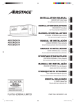
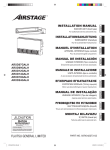
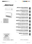
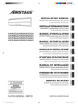
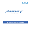
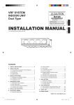
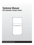
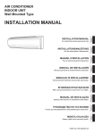
4.3.3. Pipe connection 5. INSTALLING DRAIN PIPES CAUTION Be sure to install the pipe against the port on the indoor unit and the outdoor unit correctly. If the centering is improper, the flare nut cannot tightened smoothly. If the flare nut is forced to turn, the threads will be damaged. Do not remove the flare nut from the indoor unit pipe until immediately before connecting the connection pipe. Do not use mineral oil on flared part. Prevent mineral oil from getting into the system as this would reduce the lifetime of the units. Hold the torque wrench at its grip, keeping it at a right angle with the pipe, in order to tighten the flare nut correctly. (1) Detach the caps and plugs from the pipes. (2) Center the pipe against the port on the indoor unit, and then turn the flare nut by hand. Connection pipe (Gas) Connection pipe (Liquid) WARNING Do not insert the drain piping into the sewer where sulfurous gas occurs. (Heat exchange erosion may occur) Insulate the parts properly so that water will not drip from the connection parts. Check for proper drainage after the construction by using the visible portion of transparent drain port and the drain piping final outlet on the body. CAUTION Do not apply adhesive agent on the drain port of the body. (Use the attached drain hose and connect the drain piping) • Install the drain pipe with downward gradient (1/100 to 1/50) and so there are no rises or traps in the pipe. Unsmooth draining caused by accumulated water flow in the pipe may cause clogged drain. • Use general hard polyvinyl chloride pipe (VP25) [outside diameter 32 mm]. • When the pipe is long, install supporters. • Do not perform air bleeding. Drainage may be blown out. • Always heat insulate the indoor side of the drain pipe. • If it is impossible to have sufficient gradient of pipe, perform drain lift-up. Pipe size Drain pipe (3) When the flare nut is tightened properly by your hand, hold the body side coupling with a separate spanner, then tighten with a torque wrench. (See the table below for the flare nut tightening torques.) VP25 (O.D. 32 mm) Hanging fittings 1.5 to 2 m Tighten with 2 wrenches. Holding wrench VP25 (O.D. 32 mm) Downward gradient 1/100 to 1/50 Flare nut Torque wrench PROHIBITED: Indoor unit pipe (Body side) Connection pipe Flare nut [mm (in.)] Tightening torque [N·m (kgf·cm)] 6.35 (1/4) dia. 16 to 18 (160 to 180) 9.52 (3/8) dia. 32 to 42 (320 to 420) 12.70 (1/2) dia. 49 to 61 (490 to 610) 15.88 (5/8) dia. 63 to 75 (630 to 750) 19.05 (3/4) dia. 90 to 110 (900 to 1,100) Rise Trap Air bleeding When lifting up drain: • Height of inclined pipe should be less than 850 mm from the ceiling. A rise dimension over this range will cause leakage. • Lift up the pipe vertically at the position of 300 mm or less from the unit. Downward gradient 300 mm or less 1/100 to 1/50 VP25 (O.D. 32 mm) local arrangement 850 mm or less 4.4. Installing heat insulation Horizontal or upward gradient CAUTION After checking for gas leaks (refer to the Installation Manual of the outdoor unit), perform this section. Install heat insulation around both the large (gas) and small (liquid) pipes. Failure to do so may cause water leaks. 850 mm or less VP30 (O.D. 38 mm) or more Downward gradient 1/100 to 1/50 After checking for gas leaks, insulate by wrapping insulation around the 2 parts (gas and liquid) of the indoor unit coupling, using the Coupler heat insulation. After installing the Coupler heat insulation, wrap both ends with vinyl tape so that there is no gap. Cable tie (Large) (Accessories) Coupler heat insulation No gap Body Be sure to overlap the insulation Coupler heat insulation CAUTION Must fit tightly against body without any gap. En-6 9371022260-03_IM.indb Sec1:6 5/29/2013 2:49:04 PM Working procedure (1) Install the attached drain hose to the drain port of the body. Install the hose band from the top of the hose within the graphic display area. Secure firmly with the hose band. (2) Use vinyl adhesive agent to glue the drain piping (PVC pipe VP25) which is prepared on site or elbow socket. (Apply color adhesive agent evenly until the gauge line and seal) (4) Install the heat insulation. (5) Use the attached heat insulation to insulate the drain port and band parts of the body. Attached hose band (Accessories) Locally arranged vinyl pipe Attached drain hose heat insulation (Accessories) WARNING Electrical work must be performed in accordance with this Manual by a person certified under the national or regional regulations. Be sure to use a dedicated circuit for the unit. An insufficient power supply circuit or improperly performed electrical work can cause serious accidents such as electric shock or fire. (3) Check the drainage. (See separate diagram) Install the knob faces upward 6. ELECTRICAL WIRING Before starting work, check that power is not being supplied to the all units. For wiring, use the prescribed type of cables, connect them securely, making sure that there are no external forces of the cables applied to the terminal connections. Improperly connected or secured cables can cause serious accidents such as overheating the terminals, electric shock, or fire. Securely install the electrical box cover on the unit. An improperly installed electrical box cover can cause serious accidents such as electric shock or fire through exposure to dust or water. Attached drain hose (Accessories) Attached heat insulation (Accessories) Install sleeves into any holes made in the walls for wiring. Otherwise, a short circuit could result. Use the included connection cables and power cables or ones specified by the manufacturer. Improper connections, insufficient insulation, or exceeding the allowable current can cause electric shock or fire. Do not modify the power cables, use extension cables, or use any branches in the wiring. Improper connections, insufficient insulation, or exceeding the allowable current can cause electric shock or fire. Match the terminal block numbers and connection cable colors with those of the outdoor unit (or RB unit). Erroneous wiring may cause burning of the electric parts. Securely connect the connection cables to the terminal board. In addition, secure the cables with wiring holders. Improper connections, either in the wiring or at the ends of the wiring, can cause a malfunction, electric shock, or fire. (a) Top view (b) Side view VP25 Applying area of adhesive 35 mm Hose Band Always fasten the outside covering of the connection cable with the cable clamp. (If the insulator is chafed, electric discharge may occur.) Install an earth leakage breaker. In addition, install the earth leakage breaker so that the entire AC main power supply is cut off at the same time. Otherwise, electric shock or fire could result. Always connect the earth (ground) cable. Improper earthing (grounding) work can cause electric shocks. Install the remote controller cables so as not to be direct touched with your hand. 5 to 10 mm Gauge line 4 mm or less 20 mm (c) Top view (d) Hose opening view Wind the attached heat insulation around the hose band Make sure the alignment is on top Perform wiring work in accordance with standards so that the air conditioner can be operated safely and positively. Connect the connection cable firmly to the terminal board. Imperfect installation may cause a fire. If the supply cable is damaged, it must be replaced by the manufacturer, its service agent or similarly qualified persons in order to avoid a hazard. CAUTION Make sure there are no gaps Note: Check for drainage Pour about 1 liter of water from the position shown in the diagram or from the airflow outlet to the dew tray. Check for any abnormalities such as strange noises and whether the drain pump functions normally. Earth (Ground) the unit. Do not connect the earth (ground) cable to a gas pipe, water pipe, lightning rod, or a telephone earth (ground) cable. Improper earthing (grounding) may cause electric shock. Do not connect power supply cables to the transmission or remote controller terminals, as this will damage the product. Never bundle the power supply cable and transmission cable, remote control cable together. Separate these cable by 50 mm or more. Bundling these cables together will cause miss operation or breakdown. When handling PCB, static electricity charged in the body may cause malfunction of the PCB. Follow the cautions below: • Establish an earth (ground) for the indoor and outdoor units and peripheral devices. • Cut power (breaker) off. • Touch metal part of the indoor units for more than 10 seconds to discharge static electricity charged in the body. • Do not touch terminals of parts and patterns implemented on PCB. En-7 9371022260-03_IM.indb Sec1:7 5/29/2013 2:49:05 PM 6.1. Electrical requirement 6.2. Wiring method Voltage rating Operating range 230 V 198 to 264 V • Select the power cable type and size in accordance with relevant local and national regulations. • Specifications for local wiring power cord and branch wiring are in compliance with local code. • Max. wire length: Set a length so that the voltage drop is less than 2%. Increase the wire diameter when the wire length is long. Refer to the table for the breaker specifications of each installation condition. Perform the power crossover wiring within the range of the same refrigerant system. When the crossover wiring is done, make a connection for indoor units to satisfy conditions A and B below. A. Current breaker requirements Model MCA AUXD18GALH 0.32 A AUXD24GALH 0.38 A AUXA30GALH 0.51 A AUXA36GALH 0.64 A AUXA45GALH 0.83 A AUXA54GALH 0.94 A EXAMPLE Outdoor unit or RB unit *1 Transmission Indoor unit Transmission *2 Power supply Indoor unit Remote control *2 *3 Indoor unit *2 *3 *3 MFA Breaker 20 A Breaker Power supply Remote controller (Master) Breaker Remote controller (Slave) Remote controller *1: When connecting to the Heat Recovery System, refer to the installation manual of the RB unit. *2: Earth (Ground) the remote controller if it has an earth (ground) cable. *3: When connecting the 2-wire type remote controller, Y3 is not used. MCA: Minimum Circuit Ampacity MFA: Maximum Fuse Ampacity (Crossover wiring of power supply) When the power crossover wiring is done, make it so that the total of the MCA of the connected RB units and indoor units does not exceed the 15 A. For RB unit MCA, refer to the RB unit installation manual. If the capacity of connected RB units and indoor units exceeds the upper limit, either add breakers or use a breaker with a greater capacity. B. Earth leakage breaker requirements Breaker capacity * Maximum connectable “indoor units” or “indoor units + RB units” 30 mA, 0.1 sec or less 44 or less ** 100 mA, 0.1 sec or less 45 to 128 Indoor unit Indoor unit Power supply Power supply Indoor unit Power supply Pull box Breaker Pull box Power supply * Heat pump type: indoor units, Heat recovery type: indoor units and RB units. ** If the total number of units connected to the breaker exceeds 44, either add a 30mA breaker, or use breakers with a greater capacity. 6.3. Unit wiring • Before attaching the cable to terminal block. 6.1.1. Cable specifications Power supply cable Transmission cable Remote controller cable (2-wire type) Remote controller cable (3-wire type) 6.3.1. Power supply cable Recommended cable size (mm2) Cable type 2.5 Type245 IEC57 or equivalent 0.33 0.33 to 1.25 0.33 LONWORKS compatible cable Sheathed PVC cable* Sheathed PVC cable* Remark 1ø 50 Hz 198 to 264 V 2 Cable + earth (ground) 22 AWG LEVEL 4 (NEMA) non-polar 2 core, twisted pair solid core diameter 0.65 mm Non polar 2 core Polar 3 core *: Use shielded cable in accordance with local rules for remote controller cables. 20 mm Earth (Ground) cable 30 mm A. For solid core wiring (1) To connect the electrical terminal, follow the below diagram and connect after looping it around the end of the cable. (2) Use the specified cables, connect them securely, and fasten them so that there is no stress placed on the terminals. (3) Use an appropriate screwdriver to tighten the terminal screws. Do not use a screwdriver that is too small, otherwise, the screw heads may be damaged and prevent the screws from being properly tightened. (4) Do not tighten the terminal screws too much, otherwise, the screws may break. (5) See the table for the terminal screw tightening torques. (6) Please do not fix 2 power supply cables with 1 screw. Strip 25 mm Loop Cable Screw with special washer Screw with special washer Cable end (Loop) Cable end (Loop) Terminal block Cable Do not apply branch wiring. It may result electric shock or fire. En-8 9371022260-03_IM.indb Sec1:8 5/29/2013 2:49:06 PM WARNING When using solid core cables, do not use the ring terminal. If you use the solid core cables with the ring terminal, the ring terminal's pressure bonding may malfunction and cause the cables to abnormally heat up. Tightening torque M3 screw (Transmission / X1, X2) (Remote controller / Y1, Y2, Y3) 0.5 to 0.6 N·m (5 to 6 kgf·cm) CAUTION B. For strand wiring (1) Use ring terminals with insulating sleeves as shown in the figure below to connect to the terminal block. (2) Securely clamp the ring terminals to the cables using an appropriate tool so that the cables do not come loose. (3) Use the specified cables, connect them securely, and fasten them so that there is no stress placed on the terminals. To peel the film from the lead cable, use a dedicated tool that will not damage the conductor cable. When installing a screw on the terminal block, do not cut the cable by overtightening the screw. On the other hand, an undertightened screw can cause faulty contact, which will lead to a communication failure. 6.4. Connection of wiring (4) Use an appropriate screwdriver to tighten the terminal screws. Do not use a screwdriver that is too small, otherwise, the screw heads may be damaged and prevent the screws from being properly tightened. (5) Do not tighten the terminal screws too much, otherwise, the screws may break. (6) See the table for the terminal screw tightening torques. (7) Please do not fix 2 power supply cables with 1 screw. Ring terminal Strip 10 mm (1) Remove the control box cover and install each connection cable. * Fill the wiring connecting port and remote controller connecting port with putty or heat insulation so that insects or dust will not enter the unit. * Wiring connecting port For putting through the power supply cable. Sleeve Connection cable clamp Screw with special washer Cable Screw with special washer Ring terminal Ring terminal Terminal block Cable 1 Wiring cover WARNING Use ring terminals and tighten the terminal screws to the specified torques, otherwise, abnormal overheating may be produced and possibly cause heavy damage inside the unit. 2 Control box cover Tightening torque M4 screw (Power supply / L, N, GND) 1.2 to 1.8 N·m (12 to 18 kgf·cm) 6.3.2. Transmission and Remote controller cable Transmission cable Shielded cable (no film) Power terminal board 30 mm Transmission cable and Remote controller terminal board * Remote controller connecting port For putting through the transmission cable and the remote controller cable. (2) Please firmly tighten Connection cable and Remote controller cable with the attached cable tie. 40 mm Remote controller cable For 3-wire type For 2-wire type 30 mm 30 mm • Connect remote controller and transmission cables as shown in Fig. C. Fig. C GOOD PROHIBITED Different diameter Connect to 1 side WARNING Tighten the terminal screws to the specified torques, otherwise, abnormal overheating may be produced and possibly cause heavy damage inside the unit. En-9 9371022260-03_IM.indb Sec1:9 5/29/2013 2:49:06 PM 1 CAUTION When switching the DIP switch (SW1), be sure to turn off the power supply to the indoor unit. Otherwise, the PC board of the indoor unit may be damaged. 6.5. External input and external output (Optional parts) Controller PCB DIP switch (SET 2) Apply voltage terminal Cable clamp (CNA03) OFF ON SW1 SW2 SW3 SW4 (CNA01) L, N: Power supply cable Output terminal (CNB01) (CNA02) Dry contact terminal (CNA04) (1) External input • Indoor unit can be Operation/Stop, Emergency stop or Forced stop by using indoor unit PCB CNA01 or CNA02. • “Operation/Stop” mode, “Emergency stop” mode or “Forced stop” mode can be selected with function setting of indoor unit. • Indoor unit can be Forced thermostat off by using indoor unit PCB CNA03 or CNA04. • A twisted pair cable (22 AWG) should be used. Maximum length of cable is 150 m. • Use an external input and output cable with appropriate external dimension, depending on the number of cables to be installed. • The wire connection should be separate from the power cable line. X1, X2: Transmission cable Input select Use either one of these types of terminal according to the application. (Both types of terminals cannot be used simultaneously.) Cable tie (Medium) (Accessories) ● Apply voltage terminal ([CNA01], [CNA03]) When a power supply must be provided at the input device you want to connect, use the Apply voltage terminal ([CNA01], [CNA03]). Remote controller cable DC power supply *1 12 to 24V Connect the remote controller cable Set the DIP switch (SW1) For 3-wire type Y1: Non-polar Y2: Non-polar Y3: Do not connect *1 2WIRE (Factory setting) Y1: Red Y2: White Y3: Black 3WIRE *1: If you connect the remote controller cable to the terminal Y3, 2-wire type remote controller does not work. (3) Please fix the Connection cable with cable Clamp. And then install the Wire Cover with screws. Input device 1 For 2-wire type Load resistance *a Input device 2 SW1 3WIRE Load resistance *a Input device 3 2WIRE DIP switch (SW1) Load resistance *a P.C.B CNA01 *b CNA03 connected unit *1 Make the power supply DC12 to 24V. Select a power supply capacity with an ample surplus for the connected load. Do not impress a voltage exceeding 24V across pins 1-2, and 1-3. *a The allowable current is DC 5mA to 10mA. (Recommended: DC5mA) Provide a load resistance such that the current becomes DC10mA or less. Select very low current use contacts (usable at DC12V, DC1mA or less). *b The polarity is [+] for pin 1 and [-] for pin 2 and 3. Connect correctly. (c) Bind securely When connected to Apply voltage terminals of multiple indoor units with a connected unit, be sure to make a branch outside the indoor unit using a pull box, etc. as shown on below example. CNA01 P.C.B CNA01 connected unit P.C.B CNA01 Indoor unit Load resistance CAUTION Do not bundle the remote controller cable, or wire the remote controller cable in parallel, with the indoor unit connection wire (to the outdoor unit) and the power supply cable. It may cause erroneous operation. P.C.B Indoor unit Input device 1 (4) Install control box cover. Load resistance Input device 2 DC power supply 12 to 24V Indoor unit Detail (c) En-10 9371022260-03_IM.indb Sec1:10 5/29/2013 2:49:07 PM [In the case of “Pulse” input] ● Dry contact terminal ([CNA02], [CNA04]) When a power supply is unnecessary at the input device you want to connect, use the Dry contact terminal ([CNA02], [CNA04]). P.C.B *c *c Ch 1 Ch 2 Connector Input signal Command Ch1 OFF → ON Emergency stop Ch2 OFF → ON Normal CNA01 or CNA02 CNA02 * All indoor units of same refrigerant system stops when Emergency stop operates. GND *d ● When function setting is “Forced stop” mode. [In the case of “Edge” input] Connector connected unit Input signal Command OFF → ON Forced stop ON → OFF Normal Ch1 of CNA01 or CNA02 *c Select very low current use contacts (usable at DC12V, DC1mA or less). *d The wiring is different from Apply voltage terminals. Be sufficiently careful when wiring. When connected to Dry contact terminals of multiple indoor units with a connected unit, insulate each indoor unit with relay, etc. as shown on below example. Indoor unit P.C.B K1 K4 K5 CNA02 P.C.B K3 Input device 1 Indoor unit P.C.B K2 Connector Input signal Command Ch1 OFF → ON Forced stop Ch2 OFF → ON Normal CNA01 or CNA02 * When the forced stop is triggered, indoor unit stops and Operation/Stop operation by a remote controller is restricted. * When forced stop function is used with forming a remote controller group, connect the same equipment to each indoor unit within the group. • Selection method of functions “Operation/Stop” mode or “Emergency stop” mode, “Forced stop” mode can be selected with function setting of indoor unit. ● Forced thermostat off function Indoor unit Power supply for relay CNA02 [In the case of “Pulse” input] K6 CNA02 Input device 2 [“Edge” input only] Connector Input signal Command OFF → ON Thermostat off ON → OFF Normal Ch3 of CNA03 or CNA04 K1 - K6: Relay (Device for DC Current) (2) External output NOTE : • A twisted pair cable (22AWG) should be used. Maximum length of cable is 25m. • Use an external input and output cable with appropriate external dimension, depending on the number of cables to be installed. • Output voltage: Hi DC12V±2V, Lo 0V. • Permissible current: 50mA When connected to multiple indoor units directly, it will cause breakdown. Operation behavior Edge ● Input signal type The input signal type can be selected. It is switched by DIP switch on the indoor unit PCB. DIP switch [Set 2 SW2] OFF (Factory setting) ON Input signal type Edge Pulse ● When function setting is “Operation/Stop” mode. Output select ● When indicator etc. are connected directly Pulse The width of pulse must be longer than 200msec. [In the case of “Edge” input] Connector Input signal Command OFF → ON Operation ON → OFF Stop Ch1 of CNA01 or CNA02 Operation indicator Error indicator CNB 01 Indoor unit Fan status indicator connected unit [In the case of “Pulse” input] Connector Input signal Command Ch1 OFF → ON Operation Ch2 OFF → ON Stop CNA01 or CNA02 * The last command has priority. * The indoor units within the same remote controller group operates in the same mode. ● When function setting is “Emergency stop” mode. ● When connecting with unit equipped with a power supply P.C.B Connected device 1 Connected device 2 Input signal Command OFF → ON Emergency stop ON → OFF Normal CNB 01 Connected device 3 connected unit [In the case of “Edge” input] Connector P.C.B Relay (Field supply) Ch1 of CNA01 or CNA02 En-11 9371022260-03_IM.indb Sec1:11 5/29/2013 2:49:07 PM Operation behavior Connector CNB01 Fig. A Output voltage Status External output1 Pins 1-2 0V Stop DC 12 V Operation External output2 Pins 1-3 0V Normal DC 12 V Error External output3 Pins 1-4 0V Indoor unit fan stop DC 12 V Indoor unit fan operation (3) Connection methods Screw • Wire modification Remove insulation from wire attached to wire kit connector. Remove insulation from field supplied cable. Use crimp type insulated butt connector to join field cable and wire kit wire. Connect the wire with connecting wire with solder. IMPORTANT: Be sure to insulate the connection between the wires. Option parts External input /output wire Field supply Cover Rotary switch Example: “0” Solder and insulate the connected parts. • Connection terminals and wiring arrangement Rotary switch Example: “0” In following figure, all the possible connectors are connected for description. In actual installation, you cannot connect all the connectors at once. Cable tie (Field supply): Bind to the transmission cable Transmission cable hook CNB01 CNA01 CNA03 CNA02 Setting Setting range Indoor unit address 0 to 63 Type of switch Setting example 2 IU AD × 10 IU AD × 1 REF AD × 10 REF AD × 1 CNA04 Refrigerant circuit address 7. FIELD SETTING There are 3 methods for address setting by FIELD SETTING as follows. Set by either of the methods. Each setting method is described (1) to (3) below. (1) IU AD, REF AD SW settings ............. This section (7.1. Setting the address) (2) Remote controller settings ............... Refer to the wired or wireless remote controller manual for detailed setting information. (Set IU AD, REF AD SW to 0) (3) Automatic address settings ............. Refer to the outdoor unit manual for detailed setting information. (Set IU AD, REF AD SW to 0) CAUTION Be sure to turn OFF the power before performing the field setting. 7.1. Setting the address 0 to 99 Setting example 63 (1) Indoor unit address Rotary switch (IU AD × 1)...Factory setting “0” Rotary switch (IU AD × 10)...Factory setting “0” When connecting multiple indoor units to 1 refrigerant system, set the address at IU AD SW as shown in the Table A. (2) Refrigerant circuit address Rotary switch (IU AD × 1)...Factory setting “0” Rotary switch (IU AD × 10)...Factory setting “0” In the case of multiple refrigerant systems, set REF AD SW as shown in the Table A for each refrigerant system. Set to the same refrigerant circuit address as the outdoor unit. • If working in an environment where the wireless remote controller can be used, the addresses can also be set using the remote controller. • If setting the addresses using the wireless remote controller, set the indoor unit address and refrigerant circuit address to “00”. (For information on setting using the wireless remote controller.) CAUTION Use an insulated screwdriver to set the dip switches. • Remove the cover referring to the below Fig. A. Fix the cover after addressing setting. En-12 9371022260-03_IM.indb Sec1:12 5/29/2013 2:49:08 PM Custom code setting for indoor unit Table A Rotary Switch Setting Address Address REF AD SW Refrigerant circuit × 10 ×1 0 1 2 3 4 5 6 7 8 9 10 11 12 . . . 0 0 0 0 0 0 0 0 0 0 1 1 1 . . . 0 1 2 3 4 5 6 7 8 9 0 1 2 . . . 99 9 9 Set the DIP switch SET 3 SW1, SW2, referring to the Table B. Rotary Switch Setting IU AD SW Indoor unit × 10 ×1 0 1 2 3 4 5 6 7 8 9 10 11 12 . . . 0 0 0 0 0 0 0 0 0 0 1 1 1 . . . 0 1 2 3 4 5 6 7 8 9 0 1 2 . . . 63 6 3 ON DIP switch “SET 3” OFF SW SW SW SW 1 2 3 4 Table B Do not set the indoor unit address (IU AD SW) at 64 to 99. It may result in failure. (3) Remote controller address i) 3-wire type Rotary switch (RC AD SW)...Factory setting “0” When connecting multiple indoor units to 1 standard wired remote controller, set the address at RC AD SW in sequence from 0. Setting Setting range Remote controller address 0 to 15 Type of switch Custom code B ON OFF C OFF ON D ON ON 7.3. Switching the upper limit of cooling temperature This setting can be raised the upper limit of the cooling temperature setting range. This setting can be used when connecting to the following controllers. • • • • • • Setting example 0 RC AD Example DIP switch SET 3 SW1 DIP switch SET 3 SW2 A (Factory setting) OFF OFF If 4 indoor units are connected. Indoor unit Indoor unit Indoor unit Indoor unit RC AD SW 0 RC AD SW 1 RC AD SW 2 RC AD SW 3 Wired remote controller (2-wire type) Central remote controller Touch panel controller System controller Service tool Web monitoring tool DIP switch setting Set the DIP switch SET 4 SW3 referring to the Table C. Remote controller RC AD SW Address 0 0 1 1 2 2 3 3 4 4 5 5 6 6 7 7 ON RC AD SW Address 8 8 9 9 A 10 B 11 C 12 D 13 E 14 F 15 OFF ii) 2-wire type Rotary switch (RC AD SW)...Factory setting “0” Since the remote controller address settings are automatically configured, you do not need to configure them. If configuring manually, it is necessary to configure both the indoor unit and the remote controller. For details, please refer to the remote controller manual. 7.2. Custom code setting DIP switch “SET4” SW SW SW SW 1 2 3 4 Table C DIP switch SET 4 SW3 Cooling temperature setting range OFF (Factory setting) Standard (18 to 30 °C) ON Extension (18 to 32 °C) NOTE: Please do not make a standard setup and an extension setup intermingled in remote controller group. Selecting the custom code prevents the indoor unit mix-up. (Up to 4 codes can be set.) Perform the setting for both the indoor unit and the remote controller. Code change Indoor unit Remote controller Confusion A A B C D B C D En-13 9371022260-03_IM.indb Sec1:13 5/29/2013 2:49:08 PM 7.4.1. Button name and function 7.4. Function setting • FUNCTION SETTING can be performed with the wired or wireless remote controller. (The remote controller is optional equipment) • Refer to the wired or wireless remote controller manual for detailed setting information. (Set IU AD, REF AD SW to 0) • Refer to “7.1. Setting the address” for indoor unit address and refrigerant circuit address settings. • Turn the power of the indoor unit ON before starting the setting. * Turning on the power to the indoor units initializes EEV, so make sure the piping air tight test and vacuuming have been conducted before turning on the power. * Also check again to make sure no wiring mistakes were made before turning on the power. Function details Function Filter indicator interval Filter indicator action Function number 11 20 Vertical airflow direction 23 Heat air temperature trigger Auto restart Cool Air Prevention External control 30 31 Default 01 Longer 02 Shorter 00 Enable 01 Disable 02 Display only on central remote controller 00 Default 01 High Ceiling 00 Default 01 Raise 00 Default 01 Adjust (1) 02 Adjust (2) 00 Default 01 Adjust (1) 02 Adjust (2) 03 Adjust (3) 00 Enable Fan setting when cooling thermostat OFF ○ 01 Disable ○ 00 Super low ○ 01 Follow the setting on the remote controller 00 Start/Stop 01 Emergency stop 43 ○ ○ ○ ○ ○ All 01 Display only on central remote controller 00 Follow the setting on the remote controller 01 Stop 49 lamp (Red) Adjust the filter cleaning interval notification. If the notification is too early, change to setting 01. If the notification is too late, change to setting 02. TIMER indicator lamp (Orange) OPERATION indicator lamp (Green) Regulate the airflow according to the needs of the installation location. When set to 01, the air flow will be stronger. (Cassette type only) Adjust the vertical airflow direction. All airflow direction louvers are adjusted together. (Cassette type only) Adjust the cool air trigger temperature. To lower the trigger temperature, use setting 01. To raise the trigger temperature, use setting 02. Adjust the heat air trigger temperature. To lower the trigger temperature by 6 degrees C, use setting 01. To lower the trigger temperature by 4 degrees C, use setting 02. To raise the trigger temperature, use setting 03. Enable or disable automatic system restart after a power outage. Restrain the cold airflow with making the airflow lower when starting heating operation. To correspond to the ventilation, set to 01. Allow an external controller to start or stop the system, or to perform an emergency stop. * If an emergency stop is performed from an external controller, all refrigerant systems will be disabled. * If forced stop is set, indoor unit stops by the input to the external input terminals, and Start/Stop by a remote controller is restricted. Forced stop 00 FILTER indicator Enable or disable the filter indicator. Setting 02 is for use with a central remote controller. 46 47 Details ○ 40 02 Error report target Default 00 13 Ceiling airflow Cool air temperature trigger Setting number ○ ○ Change the target for reporting errors. Errors can either be reported in all locations, or only on the wired remote. When set to 01, the fan stops when the thermostat is OFF in cooling operation. Connection of the wired remote controller (2-wire type or 3-wire type) and switching its thermistor are necessary. MANUAL AUTO button (Optional) 7.4.2. Checking the function settings • Press and hold the “MANUAL AUTO” button on the indoor unit for 3 seconds to check the function settings. It is necessary to disconnect the power in order to return to normal operation mode. (1) Indoor unit and refrigerant address indication Indication pattern Indication pattern Indoor unit address Indicator name Refrigerant address OPERATION indicator lamp ON Flash (1.0s ON/1.0s OFF) (Green) TIMER indicator lamp (Orange) Address: tens place (0.5s ON/0.5s OFF) FILTER indicator Address: ones place (0.5s ON/0.5s OFF) lamp (Red) • Indoor unit address example (Example) ADDRESS : 24 1 cycle 12 sec OPERATION indicator lamp (Green) TIMER indicator lamp (Orange) FILTER indicator lamp (Red) ON OFF ON OFF ON OFF ON 0.5s 0.5s 0.5s 0.5s 10 sec 0.5s 0.5s 0.5s 0.5s 0.5s 0.5s 0.5s 0.5s 8 sec • Refrigerant address example (Example) ADDRESS : 30 1 cycle 12 sec OPERATION indicator lamp (Green) TIMER indicator lamp (Orange) FILTER indicator lamp (Red) ON OFF ON OFF ON 1.0s 1.0s 1.0s 1.0s 0.5s 0.5s 0.5s 0.5s 0.5s 0.5s 1.0s 1.0s 1.0s 9 sec OFF OFF • Setting details Function number Item Setting number 01 Indoor unit address 00 to 63 02 Refrigeration address 00 to 99 For use with a remote controller, set all rotary switches to 0, and refer to “7.1. Setting the address” for details. All switches are set to 0 at the factory. En-14 9371022260-03_IM.indb Sec1:14 5/29/2013 2:49:09 PM (2) Others 11. ERROR CODES Indication pattern Indicator Name Indication pattern Function number; tens place (0.5s ON/0.5s OFF) Function number; ones place (0.5s ON/0.5s OFF) Setting number: (0 to 9) (0.5s ON/0.5s OFF) OPERATION indicator lamp (Green) TIMER indicator lamp (Orange) FILTER indicator lamp (Red) If you use a wired type remote controller, error codes will appear on the remote controller display. If you use a wireless remote controller, the lamp on the photodetector unit will output error codes by way of blinking patterns. See the lamp blinking patterns and error codes in the table below. Error indications OPERATION lamp (green) (Example) Function : 31, Setting number : 2 TIMER lamp (orange) Wired Remote FILTER Controller lamp (red) Error CODE 1 cycle 12 sec Error contents (1) (2) Remote controller communication error (1) (4) Network communication error (1) (6) Peripheral unit communication error (2) (6) Indoor unit address setting error 9. TEST RUN (2) (9) Connection unit number error in wired remote controller system 9.1. Test run using Outdoor unit (PCB) (3) (1) Indoor unit power supply abnormal (3) (2) Indoor unit main PCB error (3) (10) Indoor unit communication circuit (wired remote controller) error (4) (1) Indoor unit room temp. thermistor error (4) (2) Indoor unit heat ex. temp. thermistor error (5) (1) Indoor unit fan motor 1 error (5) (2) Indoor unit coil (expansion valve) error (5) (3) Indoor unit water drain abnormal (9) (15) Outdoor unit miscellaneous error (13) (1) RB unit error OPERATION indicator lamp (Green) TIMER indicator lamp (Orange) FILTER indicator lamp (Red) ON OFF ON OFF ON OFF 0.5s 0.5s 0.5s 0.5s 0.5s 0.5s 9 sec 0.5s 0.5s 11 sec 0.5s 0.5s 0.5s 0.5s 10 sec 8. CASSETTE GRILLE INSTALLATION • Operate according to the installation Manual CASSETTE GRILLE. • Be sure to confirm there is no gap between the cassette grille and main unit after installing the CASSETTE GRILLE. • Refer to the Installation Manual for the outdoor unit if the PCB for the outdoor unit is to be used for the test run. 9.2. Test run using Remote Controller • Refer to the Installation Manual for the remote controller to perform the test run using the remote controller. • When the air conditioner is being test run, the OPERATION and TIMER indicators flash slowly at the same time. 10. CHECK LIST Pay special attention to the check items below when installing the indoor unit(s). After installation is complete, be sure to check the following check items again. CHECK ITEMS If not performed correctly Has the indoor unit been installed correctly? Vibration, noise, indoor unit may drop Has there been a check for gas leaks (refrigerant pipes)? No cooling, No heating Has heat insulation work been completed? Water leakage Does water drain easily from the indoor units? Water leakage Is the voltage of the power source the same as that indicated on the label on the indoor unit? No operation, heat or burn damage Are the wires and pipes all connected completely? No operation, heat or burn damage Is the indoor unit earthed (grounded)? Short circuit Is the connection cable the specified thickness? No operation, heat or burn damage Are the inlets and outlets free of any obstacles? No cooling, No heating Does start and stop air conditioner operation by remote control unit or external device? No operation CHECK BOX Display mode : 0.5s ON / 0.5s OFF : 0.1s ON / 0.1s OFF ( ) : Number of flashing After installation is completed, has the proper operation and handling been explained to the user? En-15 9371022260-03_IM.indb Sec1:15 5/29/2013 2:49:09 PM Wired Remote Controller Display UTY-RNKY / UTY-RNKG / UTY-RNKYT (3-wire type) Error code UTY-RNRY / UTY-RNRG (2-wire type) Error icon Touch the [Status]. Touch the [Next Page] (or [previous page]) to switch to other indoor unit information. Touch the [Error Information]. 2-digit numbers are corresponding to the error code in the preceding table. For more information, refer to the installation manual of the remote controller. En-16 9371022260-03_IM.indb Sec1:16 5/29/2013 2:49:12 PM