1
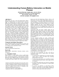
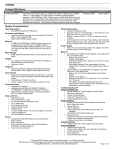
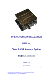
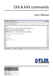
OPERATION & INSTALLATION MANUAL AIS RX PRO Version P1.4E © True Heading 2009 The manual may not in any aspect be copied without the prior authorization from True Heading AB. 1 2 3 4 5 6 7 8 9 Revision history........................................................................................................................ 4 Introduction .............................................................................................................................. 5 Glossary .................................................................................................................................... 6 Conditions ................................................................................................................................ 7 Warranty ................................................................................................................................... 8 5.1 General ...........................................................................................................8 5.2 Warranty conditions .......................................................................................8 5.3 Warranty procedures ......................................................................................8 5.4 Other issues ....................................................................................................8 Support ..................................................................................................................................... 9 AIS RX PRO .......................................................................................................................... 10 AIS RX PRO installation ....................................................................................................... 14 8.1 Introduction ..................................................................................................14 8.2 Before you start ............................................................................................14 8.3 Checking supplied materials ........................................................................14 8.4 Installing the receiver ...................................................................................14 8.5 Antenna installation......................................................................................15 8.6 GPS antenna .................................................................................................15 8.7 VHF antenna ................................................................................................17 8.8 DC Power connection...................................................................................19 8.9 LED Indicators .............................................................................................21 Data communication .............................................................................................................. 22 9.1 RS-232 ......................................................................................................................... 22 9.2 RS-422 ......................................................................................................................... 22 9.3 Communication protocol ............................................................................................. 23 9.4 Output sentences .......................................................................................................... 24 9.5 ALARM messages ....................................................................................................... 24 9.6 TEXT messages ........................................................................................................... 24 9.7 Input sentences ............................................................................................................. 25 Annex A ...................................................................................................................26 1 Revision history Version Date P1.0E 2005-10-01 Responsible Anders Bergström Approved Nils Willart P1.1E P1.2E P1.3E P1.4E Magnus Nyberg Nils Willart Nils Willart Nils Willart Nils Willart Nils Willart Nils Willart Anders Bergström 2005-11-10 2005-11-24 2006-07-25 2009-12-15 Changes First preliminary edition Second prel. edition Third prel. edition 4:th prel. ed. Edited, update 2 Introduction The AIS-RX PRO is a high performance AIS receiver built on state-of-the-art radio and microcontroller technology. The AIS-RX PRO makes it possible to apart from receive and decode AIS messages also obtain additional information about the transmitted signal. Additional information such as; exact time when data was received, in which slot it was received and the signal strength. The AIS-RX PRO also handles messages which has a corrupt checksum and outputs these in a proriatory format for later processing. All these capabilities make the AIS RX PRO a most useful tool for administrations and other qualified users to monitor the traffic on the AIS VHF Data Link (VDL) and to detect anomalies in both hardware and software used. The AIS RX PRO provides monitoring means to detect faulty operating units in terms of, transmission power, synchronization or other erroneous operation on the VDL. The AIS-RX PRO provides full AIS receiving capabilities at the same time it provides full monitoring and integrity monitoring of other AIS units operation. The AIS-RX PRO receiver exceeds the receiver requirements for AIS base station equipment to meet the though installation requirements on fixed radio sites. It provides a perfect tool for authorities, blue forces and navies to monitor and control AIS traffic within their area of operation. The AIS-RX PRO provides new means of access to the AIS data link to retreive important statistical information and analyzing the behaviour of transmitting units on the AIS data link. Picture 1 Real traffic scenario between Sweden and Bornholm (Denmark) 3 Glossary To make the reading of the manual easier we like to start up with introducing the used abbreviations and glossary: AIS BIIT C3I CRC DGPS GPS GNSS IALA IEC IMO LED NMEA NM PLL RX SOLAS SOTDMA/STDMA TDMA VDL VHF VTS Automatic Identification System Built In Integrity Test Command, Control, Communication and Information system Cyclic Redundancy Check Differential Global Positioning System Global Positioning System Global Navigation Satellite System International Association of Marine Aids to Navigation Lighthouse Authorities International Electrotechnical Committe International Maritime Organization Light Emitting Diode National Maritime Electronics Association Nautical Mile = 1852 m Phase Locked Loop Receive/Receiver Safety of Life At Sea Self Organized Time Division Multiple Access. Time Division Multiple Access VHF Data Link Very High Frequency Vessel Traffic Services (Like ATC but for ships) 4 Conditions Before you start using the AIS RX PRO product from True Heading AB it is important that you read and fully understand the installation instructions. You should only proceed with the installation if you are confident that you will be able perform a correct installation. True Heading AB cannot be held liable for any injury or damage caused by, during or because of the installation of AIS RX PRO. The AIS RX PRO is used at your own risk and it shall be remembered that AIS and GPS data depends on the full co-operation of other users and systems. AIS RX PRO is mainly a tool for monitoring the AIS frequencies and for integration to C3I systems with high demands for security and performance. The AIS RX PRO installation should be inspected from time to time and checked on its operational quality periodically by the user. Remember that the AIS RX PRO is not a replacement for other qualities during the type of operation it is intended for e.g. radar surveillance, physical inspection etc. NOT ALL VESSELS CARRY AIS. IT IS THEREFORE IMPORTANT TO KEEP PROPER LOOKOUT AT ALL TIMES AND TO USE ALL AVAILABLE MEANS TO AVOID COLLISIONS AND ACCIDENTS. GPS MAY FROM TIME TO TIME INCLUDE ERRORS: THEREFORE, THE POSITION RECEIVED FROM THE GPS BUILT IN TO AIS RX PRO SHALL ALWAYS BE VERIFED WITH OTHER AVAILABLE MEANS. 5 Warranty 5.1 General AIS RX PRO is developed and manufactured to meet high technical requirements and user demands. If installed correctly and with regular maintenance your AIS RX PRO should provide you with several years of operation and be a very useful product. 5.2 Warranty conditions - The warranty is not valid if serial number is missing, seals broken or if the AIS RX PRO has been incorrect installed. Neither is the warranty valid if instructions for connection have not been followed, faults caused by wrong usage, own made modifications or service made from none authorized service stations. - True Heading AB acknowledges that AIS RX PRO at delivery has been controlled and found operational. - True Heading AB agrees to repair or replace any faulty unit without any cost according to the conditions set forth during a period of two (2) years from day of purchase. - The warranty includes replacement or repair of faulty unit due to error in components or errors in relation to the production of the product. - The warranty covers costs for spares, labor, and return shipment. It does not include shipment from to the repair facility. - True Heading AB will never be liable under the warranty conditions for incorrect use, misuse, and incidental, indirect or consequential damages of the AIS RX PRO. - Proof of purchase is required for any warranty claim of the AIS RX PRO. 5.3 Warranty procedures True Heading AB repairs and replaces faulty parts or units. The customer is responsible for transport of the defect part or unit to True Heading or its retailer. Warranty claims shall be made to the place where AIS RX PRO was purchased or direct to True Heading AB through mail, fax or e-mail to our support department. 5.4 Other issues Proper seamanship and common sense is applicable when using AIS RX PRO and the products shall only be seen as a navaid. True Heading AB keeps the right to change the specification of the product without prior notice. IF YOU ARE NOT ABLE TO ACCEPT THE TERMS ABOVE, PLEASE RETURN THE AIS RX PRO TO YOUR RETAILER FOR FULL CREDIT BEFORE OPENED AND USED. 6 Support If you need support, please contact the closest sales representative or the place where you purchased the product. The manufacturer can also give support direct: Email: [email protected] or Fax: +46 8 545 93 910. Please register your purchase of AIS-RX PRO with True Heading AB by sending an e-mail to [email protected] stating the serial number, date of purchase, your name, address and your dealer’s name. 7 AIS RX PRO 7.1 General description The AIS-RX PRO is primarily aimed for applications were authorities, blue forces, navies or other professional users have a need to retreive information from the traffic over the AIS data link that are normally not accessible by AIS equipment available on the market today. The receiver meets the requirements set in IALA A-124 to be able to be used as a stand-alone receiver in existing AIS networks. The data output of the AIS-RX PRO complies with the data output format recommended in IALA A-124 and IEC 62230 to allow interfacing with existing network.The AIS-RX PRO also fill an important gap for use onboard due to the much higher capability than existing receiver products, as well as a design built to survive in a harsh RF environment onboard with high level of signals causing intermodulation and interference. AISRX PRO also includes unique technology providing slot data information such as slot number and timing jitter data which can be used to give an idea if the AIS data is spoofed in terms of position. The AIS-RX PRO receiver consists of two high grade VHF receivers tunable in the full maritime band, a microcontroller platform and a GPS receiver. The microcontroller platform contains the data demodulator, decoding, interface, computing capacity and power supply to provide the necessary functionality. Data Latch Enable PLL Lock Power Modem Base band Control UProc. Power CLK Data Latch Enable RxB PLL Lock Interface Antenna Splitter RSSI Control Base band RSSI Modem Power 1PPS Interface Data VHF Antenna 24 Volt DC POWER Interface RxA Interface CLK GPS Antenna GPS Power Figure 1 Block diagram of AIS RX PRO receiver RS-232/422 Data The GPS receiver provides an accurate time synchronisation referenced to UTC. The accuracy of the time achieved from the GPS is better than ±1 microsecond. The time information is used to determine the alignment of a received start flag of a received message (with correct or incorrect CRC checksum) in relation to the slot boundary. It is also used to determine the slot number of a received AIS message. The receiver module outputs a demodulated baseband signal as well as information on signal strength of the received slot data. This information is decoded, checksum controlled and output on the serial port. The information output formats are as follows: Received AIS messages with correct CRC checksum Received AIS messages with incorrect CRC checksum The signal strength in the slot(s) of successful received messages. The signal strength in the slot(s) of non-successful received messages (i.e. wrong CRC checksum) These features will allow the user to detect and measure signal strength and traffic performance in the VHF channel, giving the ability to: Detect faulty or failing installations (received signal strength from a vessels) Detect faulty synchronized transponders (jitter or sync problems) Measure VDL performance (Slot usage etc.) Detect non AIS operation on the AIS channels. 7.2 Technical specification AIS RX PRO is a compact VHF receiver with 2 parallel synthesized receiver modules tuneable in the maritime VHF frequency band. The receiver has been designed to receive and decode transmissions from AIS transponders according to the ITU R.M 1371-1 recommendation. 7.3 Electrical data Power: Power consumption: 12 Volt DC (+/- 20%) 6W 7.4 Data output Data Speed: Format: Interface: Output messages: 38400 b/s IEC 61162-1 (NMEA 0183 ver. 3) RS 232 (RS 422 Optional) VDM, BRM, ALR, TXT, RMC,!PTHAR, $PTHAJ 7.5 Receiver Frequency range: Deafault channels: Antenna impedance: Channel bandwith: Channel step: Modulation: Sensitivity: Co-channel rejection: Adjacent channel selectivity: Spurious response rejection: IMD response rejection: 155 - 163 MHz AIS1 161.975 MHz AIS2 162.025 MHz 50 ohm 25 kHz 12.5 kHz FM/GMSK BER 10-3 @ -115 dBm -10 dB 70 dB 70 dB 74 dB 7.6 Physical data Rack mount: L x W x H: Weight: 19’’ Rack – 1 HE 225 mm x 482 mm x 43.6 mm 1.9 kg Boxed: L x W x H: Weight: 170 mm x 246 mm x 48 mm 1.7 kg Connectors: Data output port: Power connector: VHF Antenna: BNC female GPS Antenna: TNC female 9 pin D-sub connector Jackable, terminal connector 7.7 GPS Receiver type: Sensitivity: Accuracy: Antenna impedance: Antenna DC feed: 12 parallel channels - 165 dBW minimum Position: < 15 meters, 95% typical Velocity: 0.1 knots RMS steady state 50 ohm 3V NMEA output format: $GPRMC 8 AIS RX PRO installation 8.1 Introduction AIS RX PRO is quick and simple to install. For the installation you will need antennas (VHF and GPS), cables, connectors and a 12 V DC power supply. When the receiver hardware has been installed the data cable is ready to connect to the PC. Please be aware of that the display software used with the receiver must be compatible with the standard AIS messages in order to show AIS targets. The receiver data serial port outputs the received data using 38400 bits/s. The data format is ASCII, using 8 bits, no parity, 1 stop bit and no flow control. 8.2 Before you start This part describes the most important information you need to install the AIS RX PRO receiver. Please read the entire manual to get a full understanding of how to install and operate your AIS RX PRO. Visit our webpage (www.trueheading.se) for updates on manuals etc. 8.3 Checking supplied materials Check that you have received all parts supplied with the AIS RX PRO and that the delivered equipment has not been damaged during transport. If the equipment has been damaged, please contact your transporter. If parts are missing, please contact your sales representative or our support. 8.4 Installing the receiver AIS RX PRO is made to be installed in a protected environment (indoors) and shall therefore be placed where it is well protected from water and humidity. AIS RX PRO should not be placed close to generators, electrical motors or compressors since these can interfere with the reception. A suitable place of installation is close to a location where antenna feeders, data communication cables and power is available. AIS RX PRO also has LED indicators for power, GPS, and AIS reception status. It is therefore good practice to install the unit so that these indicators are viewable to provide easy monitoring of performance and functionality. The boxed version installs easily on bulkheads or panels using the integrated backpanel bracket. Figure.2 Measurements for the installation of the AIS RX PRO. 8.5 Antenna installation Install the GPS and VHF antenna in a suitable position where the antennas are free from obstructing metal objects (see further below). The antenna cables should be run the shortest possible way and cable type selected depending on the length to avoid losses. All connectors should be properly fastened to avoid losses and connectors sealed using self-amalgamating rubber tape to prevent water instrusion causing degradation of the system. Cable selection guide: Length < 10 m cables > 10 m cables Cable types RG58C/U RG213/U 8.6 GPS antenna The GPS antenna should be active with a built in LNA (Low Noise Amplifier). AIS RX PRO provides a DC feed to the LNA through the antenna cable. The GPS antenna should have the following charachteristics: Antenna type: Power supply: LNA gain: Impedance: Connector: RHCP, patch or quadrifilar type. 3V DC 5 - 25 dB 50 ohm TNC male The GPS antenna should be placed with an unobstructed view of the sky. To prevent multipath reflections which can cause disturbances in the receiption of the GPS satellites, do not place the antenna close to large metal objects. The GPS antenna should not be mounted close to Inmarsat and S-band radar antennas. The table below shows recommended safe distances to equipment that could cause interference with the AIS receiver. Antenna /equipment Radar antenna, X-band High efficiency engines HF or VHF antennas High current AC power cables Satellite communication antennas Safe distance 1, 5 m (5 ft) 1 m (3 ft) 3 m (10 ft) 1 m (3 ft ) 4 m (13 ft) Connect the GPS antenna cable to the TNC connector as shown in the picture below: GPS antenna connector (TNC) Figure 3 GPS antenna connection GPS antenna connector (TNC) Figure 4 GPS antenna connection 8.7 VHF antenna AIS RX PRO is shipped without antennas since the requirements for antennas and cables can be different between installations. A suitable VHF antenna is necessary for proper operation. The type of VHF antenna used should be choosen with respect to the intended use of the receiver. True Heading can provide suitable antenna solutions depending on needs. The VHF antenna installation is often a compromise between the following: Separation between the AIS and other antennas Free line-of-sight, 360 degrees coverage Antenna height Antenna separation To avoid interference from transmitters the AIS RX PRO antenna should be separated as much as possible from other VHF antennas. The best separation is accomplished if the antennas are placed on different heights or on different sides of the mast or ship. Line of sight To provide the best possible reception the antenna should be placed with unobstructed view of the horizon. Avoid installations close to larger metal objects as these will attenuate signals in certain directions. Antenna height AIS use two frequencies in the maritime VHF band. The coverage range in this frequency band is almost the same as the line of sight. This means that the higher you put your antenna the longer range will be obtained. Recommended antenna types: Type: Gain: Impedance: Vertical 1/4 or 1/2 λ radiator or high gain directional 0 – 3 dBd 50 ohm IMPORTANT NOTICE! If the receiver is used at a fixed location and the antenna is mounted in a tower, mast or on top of a building, the antenna installation must be proteceted against lightning. We recommend that the antenna used is DC grounded and the shield (outer braid) of the coaxial cable connected to the metal structure with a grounding strap. The coaxial cable end connecting to the receiver should be protected using a lighting arrestor of gas-discharge type. Use a gas-discharge capsule with a 90 volt discharge rating. The lightning arrestor should be grounded to the protective grounding network at the site. Please note that this ground is separated from the AC protective ground on the power supply side. It is also recommended the the GPS antenna and cable is proteceted in the same manner. Please note that the GPS cable feeder also carry a DC currenty feed for the antenna built-in amplifier. The protection device use must be compatible with this DC feed. Please contact True Heading for further recommendations and support. The VHF antenna is connected to the BNC connector as indicated in the figure(s) below: VHF antenna connection (BNC) Figure 5 VHF antenna connection boxed version. VHF antenna connection (BNC) Figure 6 VHF antenna connection 19” rack version. 8.8 DC Power connection Connect the AIS RX PRO to 12 V DC supply via a 1 A fuse. On the 19’’ rack mounted unit a fuse is already fitted on the rear panel. The AIS RX PRO comes with a power cable fitted with a fuseholder. When connected to a 12 VDC the power (PWR) LED indicator shall light green. Power LED indicator DC power connector 9-pin D-sub data connector Figure 7 Connections, boxed version Power LED indicator Figure 8 19” rack version front panel, power LED indicator 9-pin D-sub data connector DC power receptacle Figure 9 19” rack version, data port and DC power connection 8.9 LED Indicators AIS RX PRO has four (4) LED indicators used for operating status indication. The power indicator (PWR) indicates that power is connected and show green fixed light when the AIS RX PRO is connected to a DC power supply. The power LED is turned on and off by the software. If the power LED fails to light, the BIIT function (Built In Integrity Test) has detected a fatal error which prevents operation. The power LED may flash occasionally. This is normal and indicates that the unit has received an AIS message containing a CRC checksum error. This message is output on the presentation port as a proprietary message (!PTHAR). If the receiver is subjected to conditions with severe RF disturbances the green LED may go off completely (the blue and yellow LED’s may still flash) for the duration of the disturbance. If this happens, the position of the antenna should be checked. The GPS indicator LED flashes with blue light (one flash every second) when the built in GPS receiver is synchronized to UTC and has acquired a position fix. If the LED does not flash the GPS has not yet acquired a position fix. Figure 10 AIS-RX PRO frontpanel indicators The Rx 1 LED will flash with a yellow light when the AIS RX PRO receives data on the AIS 1 channel. The Rx 2 LED will flash when data is received on the AIS 2 channel. The receive LED’s should flash intermittently when receiving successful AIS slot transmissions. If the RX LED´s are not flashing and the receiver is in an area were AIS signals are likely to be received the VHF antenna installation should be checked. In some cases RF filters will be needed to remove or reduce interference from nearby transmitters. True Heading AB can offer tailored filter solutions in case it’s needed. 9 Data communication The communication to and from the AIS RX PRO is using the IEC 61162-1/NMEA 0183 ver 3 protocol standard. The electrical interface conforms to the RS232 interface standard. Other interface standards are available on request. 9.1 RS-232 The AIS RX PRO is in its standard version equipped with a serial RS-232 interface using a physical 9-pin D-sub female connector. The configuration of the RS-232 interface is as follows: 9-Pin Female D-sub (AIS RX PRO) 1 2----------Data output 3----------Data input. 4 5----------Signal ground 7 8 9 The AIS RX PRO should be connected using a pin to pin wired serial data cable with 9-pin D-sub connectors at the ends (female- male). The default databit rate is 38400 bits/s 9.2 RS-422 The AIS RX PRO can also be provided with an optional opto isolated RS 422 interface instead of the RS 232. The configuration of the RS-422 interface is as follows: The conector is a 9-Pin Female D-sub connector. 1----------Ground 2----------RX + 3----------TX + 4 5 7----------RX 8----------TX 9 9.3 Communication protocol The AIS RX PRO is built to conform to the message standard defined in the IALAA124 and IEC 62230-1 documents to provide compatibility with existing shore infrastructure equipment. A full description of the sentence formats can be found in ANNEX A 9.4 Output sentences Sentence !AIVDM $AIBRM $AIALR $AITXT $GPRMC !PTHAR $PTHAJ 9.5 Comment Output of received AIS data with message ID 0 - 63 (of which 1-24 are presently defined by ITU-R M.1371-1/2). The data is defined by ITU-R M.1371-2. Received Signal Strength (Once per received VDL message) Integrity Alarm message BIIT Warning/Notification Position data from the built-in GPS receiver containing UTC second, Navstatus, Position, SOG, COG, Mode indicator, Date and Time (once per second) Propriatory message using the same message structure as !--VDM, but outputs received VDL data in raw format with CRC error Propriatory message outputting time, jitter and slot information of the received data, the message follows every !PTHAR or !--VDM. ALARM messages The AIS RX PRO outputs the following ALR sentences when the appropriate alarm condition is fulfilled (see also IALA Recommendation A-124 or IEC 62230-1 for further information). Alarm ID 003 004 026 9.6 Alarm’s description text AIS: Rx channel 1 malfunction AIS: Rx channel 2 malfunction AIS: No sensor position in use Comment PLL lock failure PLL lock failure GPS is not navigating, no position, time or jitter measurement TEXT messages The AIS RX PRO outputs the following TXT sentences when the appropriate status inccation condition is fulfilled: Text identifier 007 Text message Comment AIS: UTC clock lost 042 AIS: UTC clock ok The AIS RX PRO has lost internal the operation clock for time and jitter measurements (GPS reception problem) The AIS RX PRO has reaquired the internal clock for time and jitter measurements (GPS back in operation) 9.7 Input sentences Sentence $AIACK $AIBCF $AICAB Comment Acknowledgement of alarm state in the $AIALR message Configuration of parameters in the AIS RX PRO Reboot Command Annex A IEC 61162-1 Sentences used ACK – General Base Station Configuration This sentence is used to acknowledge alarm condition reported by the AIS RX PRO $--ACK, xxx*hh<CR><LF> Where xxx is the alarm number as indicated by the alarm message ALR – Set alarm state AIS RX PRO alarm condition and status. This sentence is used to report an alarm condition on an AIS RX PRO and its current state of acknowledgement. BCF – General Base Station Configuration This sentence is used to configure the static Base Station parameters when it is initially installed, and later in order to make changes to the way it operates. Dynamic parameters (e.g. UTC and position of a moving Base Station) are input in a different way. This sentence supports system administration of the AIS Base Station operation. $--BCF,xxxxxxxxx,x,llll.ll,a,yyyyy.yy,a,x,xxxx,xxxx,xxxx,xxxx,x,x,x,x,aa*hh<CR><LF> │ │ │ │ │ │ │ │ │ │ │ │ │ │ │ │ │ │ │ │ │ │ │ │ │ │ │ │ │ │ │ └─ Base Station talker ID │ │ │ │ │ │ │ │ │ │ │ │ │ │ └─── Mes repeat indicator │ │ │ │ │ │ │ │ │ │ │ │ │ └───── VDL message retries │ │ │ │ │ │ │ │ │ │ │ │ └─── Power level channel B 6 │ │ │ │ │ │ │ │ │ │ │ └───── Power level channel A 6 │ │ │ │ │ │ │ │ │ │ └─────── Tx channel B 5 │ │ │ │ │ │ │ │ │ └──────────── Tx channel A 5 │ │ │ │ │ │ │ │ └──────────────── Rx channel B 5 │ │ │ │ │ │ │ └───────────────────── Rx channel A 5 │ │ │ │ │ │ └───────────────────── Position accuracy 4 │ │ │ │ └────┴────────────────── Longitude – E/W 3 │ │ └────┴───────────────────────────── Latitude – N/S 3 │ └──────────────────────────────── Position Source 2 └────────────────────────────────────── MMSI of the Base Station 1 NOTES 1. This Data Field is the MMSI of the Base Station. In early Base Stations, this Data Field s et the MMSI of the Base Station. For Base Stations built to comply with IEC 62320 -1, this Data Field should not be used. The attached “Comment Block” parameter -code “d:” should be used to test if this sentence is intended for this Base Station. The Base Station should ignore this sentence if the parameter-code “d:” value in the attached Comment Block does not match the internal “Unique Identifier” (Also, see the SID sentence.). 2. Identifies the source of the position: 0 = surveyed position 1 = internal EPFD in use 2 = external EPFD in use 3 = internal EPFD in use with automatic fall back to surveyed position 4 = internal EPFD in use with automatic fall back to external EPFD upon failure of internal EPFD 5 = external EPFD in use with automatic fall back to s urveyed position 6 = external EPFD in use with automatic fall back to internal position source upon failure of external position source 3. 4. Surveyed position of the Base Station. The position is only applicable to fixed Base Stations. Within the Base Station, the “electronic position fixing device” Data Field must be set to a value of 7 indicating a surveyed position. Mobile or non-fixed Base Stations receive their position information by another means. 0 = low > 10m. 1 = high < 10m; differential mode of DGNSS. 5. 6. VHF channel number, see ITU-R M.1084, Annex 4. 0 = high power (Nominal 12.5 Watts) 1 = low power (Nominal 2 Watts) 2 to 9 reserved for future use BRM - Base Station Options Reply of Received Messages This sentence will give optional information of a received Message of a Base Station. The output sentence of the received Message (VDM) must be just before this sentence. $--BRM,,,aaaa,bbbb*<CR><LF> aaaa: bbbb: signal strength of previous received message Slot number CAB – Control AIS Base Station This sentence is used to turn on or off the transmission of channel A and B on an AIS Base Station and also to command a restart of the Base Station. This sentence supports system administration of the AIS Base Station operation . $--CAB,x,x,x,x*hh<CR><LF> │ │ │ └─ │ │ └── │ └──── └────── 3 Reset 2 Restart 1 Channel B transmission Channel A transmission 1 NOTE 1 Not used since AIS RX PRO is not a transmitting device NOTE 2 This field commands the AIS RX PRO to restart operations to last known configuration. The value of “1” indicates a restart. If a restart is not being indicated, this field is null. NOTE 3 Not used $PTHAJ - AIS data Slot and Jitter message: The $PTHAJ sentence gives information of when a message is received in terms of; channel the message was received in, in which slot it was received in and how it is referenced to the start of the slot boundary. $PTHAJ, a,bbbb,ccccc.c*hh<CR><LF> a: bbbb: c: ddddd.d AIS Channel (1 or 2) Slot number (0-2249) Time character (P = positive, N = negative) Start time in relation to TTS (0 – 13333.3) in micro seconds Transmissions that are received before expected start time is regarded as negative time (- sign), transmissions hat are received after expected start time is regarded as positive time (+ sign) !PTHAR – AIS VHF Data Link message with wrong HDLC Checksum This sentence is identical with the !--VDM sentence but contains a received message that has been found with wrong HDLC checksum. !PTHAR sentence indicates that the information coming is a received AIS message, but contains bit error(s) in the data string. The difference between !AIVDM and !PTHAR sentence is only the Talker ID, Sentence ID and the knowledge of wrong CRC in data content RMC Recommended minimum specific GNSS data Time, date, position, course and speed data provided by a GNSS navigation receiver. This sentence is transmitted at intervals not exceeding 2 s and is always accompanied by RMB when a destination waypoint is active. RMC and RMB are the recommended minimum data to be provided by a GNSS receiver. All data fields must be provided, null fields used only when data is temporarily unavailable. ! --VDM – AIS VHF data-link message This sentence is used to transfer the entire contents of a correct received AIS message packet, as defined in ITU-R M.1371-1/2 and as received on the VHF Data Link (VDL), using the “six-bit” field type. The structure provides for the transfer of long binary messages by using multiple sentences. NOTE 1 The length of an ITU-R M.1371 message may be long and may require the use of multiple sentences. The first field specifies the total number of sentences used for a message, minimum value 1. The second field identifies the order of this sentence in the message, minimum value 1. These cannot be null fields. NOTE 2 The Sequential message identifier provides a message identification number from 0 to 9 that is sequentially assigned and is incremented for each new multi-sentence message. The count resets to 0 after 9 is used. For a message requiring multiple sentences, each sentence of the message contains the same sequential message identification number. It is used to identify the sentences containing portions of the same message. This allows for the possibility that other sentences might be interleaved with the message sentences that, taken collectively, contain a single message. This field shall be a null field when messages fit into one sentence. NOTE 3 The AIS message reception channel is indicated as either "A" or "B." This channel indication is relative to the operating conditions of the AIS when the packet is received. This field shall be null when the channel identification is not provided. The VHF channel numbers for channels "A" and "B" are obtained by using an ACAsentence "query" of the AIS. NOTE 4 The maximum string length of encapsulation is limited such that the total number of sentence characters does not exceed 82. This field supports a maximum of 62 valid characters for a message transferred using multiple sentences, and 63 valid characters for a message using a single sentence. NOTE 5 To encapsulate, the number of binary bits must be a multiple of six. If it is not, one to five "fill bits" are added. This parameter indicates the number of bits that were added to the last 6-bit coded character. This value shall be set to zero when no "fill bits" have been added. This cannot be a null field. . TXT – Text transmission For the transmission of short text messages. Longer text messages may be transmitted by using multiple sentences. NOTE 1 Text messages may consist of the transmission of multiple messages all containing identical field formats. The first field specifies the total number of messages, minimum value = 1. The second field identifies the order of this message (message number), minimum value = 1. For efficiency, it is recommended that null fields be used in the additional sentences; otherwise data is unchanged from the first sentence. NOTE 2 The text identifier is a number, 01 to 99, used to identify different text messages. NOTE 3 ASCII characters, and code delimiters if needed, up to the maximum permitted sentence length (i.e. up to 61 characters including any code delimiters).