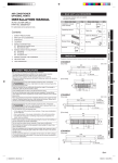
1
AIR CONDITIONER
OPTIONAL PARTS
PART NO. 9378782037-03
INSTALLATION MANUAL
For authorized service personnel only.
OPERATION Indicator lamp
(GREEN)
Do not turn on the power until all installation work is
complete.
MANUAL AUTO button
•
Let the customer keep this installation manual
because it is needed when the air conditioner or IR
receiver unit is serviced or moved.
CAUTION
This mark indicates procedures
which, if improperly performed,
might possibly result in personal
harm to the user, or damage to
property.
Do not wire the IR receiver unit wire together with or
parallel to the transmission cables, remote controller
cables and power supply cables of the indoor unit. It may
cause erroneous operation.
Français
Installation work must be performed in accordance with
national wiring standards by authorized personnel only.
Remote control signal receiver
3. INSTALLING THE IR RECEIVER UNIT
1. REMOVING THE CONTROL BOX COVER
1 Remove the screws.(2 places)
2 Slide the control box cover in the direction of the arrow.
3 Remove the control box cover.
EλληvIkά
Do not install the IR receiver unit wire near a source of
electromagnetic waves.
Español
For the air conditioner to operate satisfactorily, install it as
outlined in this installation manual.
FILTER Indicator lamp
(RED)
TIMER Indicator lamp
(ORANGE)
Italiano
WARNING
This mark indicates procedures
which, if improperly performed,
might lead to the death or serious
injury of the user.
Deutsch
2. FUNCTIONS
UTY-LRH½B1
English
IR RECEIVER UNIT
1. MAIN UNIT AND ACCESSORIES
Name and Shape
Q’ty
Application
For receiving the
signal from the remote control unit
IR receiver unit
Português
The following installation parts are supplied. Use them as
required.
Control box cover
Prevent IR receiver
unit from falling down
Strap
Русский
1
Slid
e
Türkçe
1
En-1
9378782037-03_IM.indb 1
2012-7-13 9:59:16
2. INSTALLING THE IR RECEIVER UNIT
1 Mount the corner (figure to the drainpipe) of the
decoration panel that has the “DISPLAY” mark onto the
IR receiver unit.
3 Hang the STRAP on the hook of the decoration panel.
After that, mount the IR receiver unit onto the decoration
panel.
Decoration
Panel
Hook
Strap
Pipe
side
Dra
in s
ide
CAUTION
This corner must be mounted onto the IR receiver unit.
2 Insert the wire from the IR receiver unit into the wiring
hole as shown in the figure below and pull it into the
decoration panel.
3. WIRING
1 Connect the connector to the Board in the control box.
2 Fix the wires with the hook.
3 Bundle the 2 Flap wires to the IR receiver unit wire as
shown in the figure below.
Fix the wires with the hook
Tighten
with cable
tie (Field
supply)
Wiring hole
Connect the connector
Wire for flap
Wire from IR receiver unit
Wire from IR receiver unit
Wire for Flap
Board Y
4. INSTALLING THE CONTROL BOX COVER
1 Secure the control box cover in the procedure that is
reverse to the steps in “1. REMOVING THE CONTROL
BOX COVER”.
IR receiver unit
En-2
9378782037-03_IM.indb 2
2012-7-13 9:59:38