1
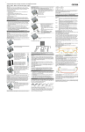
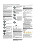
Programmable Solar Charge Controller with Negative Ground CXN10, CXN20, CXN40 User Manual English, Page 1 Dear Customer, Thank you very much for buying this Phocos product. With your new CXN controller you own a state-of-the art device which was developed according to the latest available technical standards. It comes with a number of outstanding features, such as: Multifunctional LC display Programmable Low Voltage Disconnect with new ALVD (Adaptive Low Voltage Disconnect) Sophisticated programmable nightlight function Excess Energy Management (EEM) for better utilization of your solar system Complete electronic protection Negative Grounding This manual gives important recommendations for installing, using and programming as well as remedies in case of problems with the controller. Read it carefully in your own interest and mind the safety and usage recommendations at the end of this manual. Major Functions The charge controller protects the battery from being overcharged by the solar array and from being deep discharged by the loads. The charging characteristics include several stages which includes automatic adoption to the ambient temperature. The charge controller adjusts itself automatically to 12V or 24V system voltage. The pushbutton allows switching the load on and off manually. The charge controller can be programmed for lighting applications. The controller provides a control output for special loads that make use of excess energy, such as Phocos DCL DC voltage converter. Additionally, it has a serial interface which can be used with an optional interface adapter (CX-I). The charge controller has a number of safety and display functions. Connect the wires leading to the solar array with correct polarity. To avoid any voltage on the wires, first connect the controller, then the solar array. Mind the recommended wire size: CXN10: min 2.5 mm² CXN20: min 4 mm² CXN40: min 10 mm² 5 REMARK: place positive and negative wire close to each other to minimize electromagnetic effects. REMARK: Solar panels provide voltage as soon as exposed to sun light. Mind the solar panel manufacturer’s recommendations in any case. To avoid voltage at the load terminal, push the 6 button to shut off the load output. Connect the wires leading to the loads with correct polarity. Mind the recommended wire size: CXN10: min 2.5 mm² CXN20: min 4 mm² CXN40: min 10 mm² Fasten the strain relieves. 7 Recommendations for Use If you intend to use the Excess Energy Management output, follow these steps: a. Mount the excess energy signal wires as shown in the picture beside. b. Connect the signal wires to the excess energy management input of the appropriate load (e.g. Phocos DCL DC voltage converter) c. Reconnect the 4-pin terminal to the left socket of your CXN d. Set the interface function to “Serial Interface EXCESS ENERGY & CURRENT DATA” in Programming Menu 8 Close the terminal lid. The regulator warms up during normal operation. If there is insufficient ventilation (e.g. in an installation cabinet), the controller limits the solar charge current to prevent overheating. The regulator does not need any maintenance or service. Remove dust with a dry tissue. It is important that the battery gets fully charged frequently (at least monthly). Otherwise the battery will be permanently damaged. A battery can only be fully charged if not too much energy is drawn during charging. Keep that in mind, especially if you install additional loads. Mounting and Connecting the Charge Controller The controller is intended for indoor use only. Protect it from direct sunlight and place it in a dry environment. Never install it in humid rooms (like bathrooms). The controller measures the ambient temperature to adopt the charging voltage, therefore it must be installed in the same room as the battery. The controller warms up during operation. It shall be installed on a non flammable surface only. REMARK: Connect the controller by following the steps described below to avoid installation faults. Open the terminal lid. Now you have successfully connected your CXN controller. 1 Grounding the Solar System As long as the solar array supplies enough voltage to charge the battery, this is indicated by up-moving bars alternately to the state of charge display. In normal operation the loads can be switched on and off by pushing the button. This is indicated in the display: Load Load manually O N manually O FF Special conditions are shown in the LC display if the Low Voltage Disconnect function shuts off the load output or in case of various other error conditions. See section ERROR DESCRIPTION for details. Acoustics Signals The controller has an acoustic signal which indicates the change of the state of charge. This function can be deactivated in Programming Menu 7. Description of Functions Low Voltage Disconnect Function (LVD) The controller has 5 different modes to protect the battery from being deep discharged: Mode 1 Disconnect at 11.4 V (at nominal load current) up to 11.9 V (at no load current). Normal operation mode for good battery protection. Mode 2 Disconnect at 11.0 V (at nominal load current) up to 11.75 V (at no load current). Mode with lower disconnection point. Battery is cycled deeper, this can shorten battery lifetime. Mode 3 Disconnect at 11.0 V to 12.2 V depending on load current and previous charging cycles. This adaptive mode leads to longer lifetime of the battery because it allows recovery of the battery by full recharge. Maximum battery life. Mode 4: Disconnect at 11.5 V fixed setting. Appropriate if bypass loads draw current directly from battery. Mode 5: Disconnect at 11.0 V fixed setting. Appropriate if bypass loads draw current directly from battery. Mode with lower disconnection point. Battery is cycled deeper, this can shorten battery lifetime. The controller is preset to Mode 1 from the factory. Use Programming Menu 2 to change the setting (see back page). In case of doubts which mode to choose, consult your dealer because this has to be evaluated depending on the battery used. Excess Energy Management Function (EEM) The controller provides a built-in excess energy management function. This function, in combination with especially designed loads (e.g. Phocos DCL DC voltage converter), allows to make use of excess energy which would be lost otherwise because of the overcharge protection of the battery. A better utilization of the solar system is the benefit. Also the battery treatment is improved because more energy comes directly from the solar panel instead of the battery. Ask you dealer about available loads that can make use of excess energy. To connect your Excess Energy load with the controller, see picture 8 (signal wires). Nightlight Function The CXN controller comes with a sophisticated nightlight function. It controls the load output at night and is widely programmable. There are 2 modes available: DUSK TO DAWN and EVENING/MORNING. The mode can be selected in Programming Menu 3. Light on Dusk to Dawn Light off 2 Evening Timing Remove the screws from the strain relief and take off the strain relief bridges. Morning Timing Mid of night Light on Light off Number of hours or time to mid of night time after mid of night ½ 3 Mount the controller to the wall with screws that fit to the wall material. Use screws with 4 to 5 mm shaft and max. 9 mm head diameter, no counter sunk. Mind that the screws have to carry also the force applied by the wiring. Mind also the minimum required distance to floor and ceiling, this is necessary for ventilation reasons. A DIN Rail mounting plate is available as an accessory (CX-DR2). This allows mounting the controller on a standard 35mm DIN rail. Use the screws supplied with the mounting plate to fix it to the controller. Be aware that the CXN is negative grounding and the negative terminals of the CXN controller are connected internally and therefore have the same electrical potential. If any grounding is required, always do this on the negative wires. >10cm > 4ą Self Test As soon as the controller is supplied with power either from the battery or the solar array, it starts a self test routine. This is indicated first by running LCD bars for approx. 0.5 seconds, and then the firmware version is displayed in coded symbols for about another second (this is for service purposes only). Then the display changes to normal operation. System Voltage >10cm > 4ą Connect the wires leading to the battery with correct polarity. To avoid any voltage on the wires, first connect the controller, then the battery. Mind the recommended wire length (min 30 cm to max approx. 100 cm) and the wire size: CXN10: min 2.5 mm² CXN20: min 4 mm² CXN40: min 10 mm² Wrong polarity will cause a permanent warning sound. WARNING: If the battery is connected with reverse polarity, the load terminals will also have the wrong polarity. Never connect loads during this condition! REMARK: The controller has a built-in voltage drop compensation which automatically compensates battery wire voltage drops of up to 250 mV. REMARK: Mind the recommendations of your battery manufacturer. We strongly recommend connecting a fuse directly to the battery to protect any short circuit at the battery wiring. The fuse must take the charge controller nominal current: CXN10: 15A, CXN20: 30A, CXN40: 50A 4 Starting up the Controller The controller adjusts itself automatically to 12 V or 24 V system voltage. As soon as the voltage at the time of start-up exceeds 20.0 V, the controller implies a 24 V system. If the battery voltage is not within the normal operation range (approx. 12 to 15.5 V or approx. 24 to 31 V) at start-up, a status display according to the section ERROR DESCRIPTION occurs. Battery Type The controller is preset to operate with lead acid batteries with liquid electrolyte. If you intend to use a VRLA battery (GEL type) you can adjust the controller in Programming Menu 1 (see back page). The equalization charge is deactivated then. In case of any doubts consult your dealer. Display Functions and Acoustic Signals LC Displays In normal operation mode the controller displays the state of charge (available energy) of the battery. Any change of the state of charge (SOC) to a lower status is additionally signalled acoustically. System conditions are displayed as follows: > 80% 60...80% 1x 35...60% 2x 10...35% 3x < 10% 5x Flashes Load Disconnect 25x The percentage corresponds to the available energy until Low Voltage Disconnect in relation to a fully charged battery. or Number of hours ½ If EVENING/MORNING is selected, Programming Menu 5 allows choosing the MORNING timing behaviour, and Programming Menu 4 allows choosing the EVENING timing behaviour. Mind that the load output is switched off as soon as the battery has reached the Low Voltage Disconnect threshold. The Low Voltage Disconnect has priority above the nightlight function. “Mid of night” is detected automatically as the middle between dusk and dawn, no real time setting is required. It may take some days until the controller has “learnt” midnight. This method can cause some inaccuracy but avoids any clock readjustment. The controller’s “Mid of night” can be different from the real time midnight depending on your location. The controller recognizes day and night based on the solar array open circuit voltage. In Programming Menu 6 this day/night threshold can be modified according to the requirements of the local conditions and the solar array used. Threshold setting range 7.7 / 15.4 V Switching point day > night Switching point night > day 4.9 / 9.8V (factory setting) 1.0 / 2.0V Curve of open-circuit voltage solar array The two voltage levels before/ after the slash are valid for 12 V and 24 V systems respectively. To find the right value, we recommend measuring the solar array open circuit voltage at the time when twilight has reached the level when the controller should switch on/off. This value (the closest available) can then be set according to the description in the programming section. Programming Lock-out By pushing the programming button for 8 s in normal operation mode the programming lock-out is activated to prevent any accidental settings change. Another 8 sec push releases the lock-out. Programmable Solar Charge Controller with Nightlight Function CXN10-1.1, CXN20-1.1, CXN40-1.1 User Manual English, Page 2 Optional Functions Interface and Datalogger (CXI and CXCOM) The controller comes with a serial interface, which can be connected to a PC with an optional interface adapter (CX-I) (see interface adapter manual for details). In Programming Menu 8 (Serial interface BIDIRECTIONAL, NO EXCESS ENERGY , is also default setting) the behaviour of the serial interface can be modified. WARNING: The combination of different errors may cause damage to the controller. Always remove errors before continue connecting the controller! Error condition External Temperature Sensor (CXNT) (1) Display Reason Battery is low Overcurrent / Short circuit of loads Loads are not supplied Flashes With the optional temperature sensor (CXNT), CXN can measure the battery temperature and adjust the charging voltage accordingly to extend the battery life span. See CXNT manual for details. You enter the programming mode with a long push (2s-8s) on the button. The programming menu structure is described as below. Menu 1: Battery type In this menu, you can select the proper battery type - liquid electrolyte or GEL (VRLA) according to your PV system to get better charge of your battery. The default battery type is liquid electrolyte. In this menu, you can set 5 different LVD modes to protect the battery from being deep discharged. Please see section DESCRIPTION OF FUNCTIONS for details. The default low voltage disconnect (LVD) setting is Mode 1 - Disconnect at 11.4 V (at nominal load current) up to 11.9 V (at no load current). Menu 3: Nightlight function (type) In this menu, you can set the type of nightlight function or switch off the nightlight function of your CXN controller. The default setting of nightlight function type is OFF. Menu 4: Nightlight function (evening settings) When the nightlight function type is set to EVENING/MORNING mode, you can set the load ON hours after sunset in this menu. The default load ON hours after sunset is 0 hr. Menu 5: Nightlight function (morning settings) When the nightlight function type is set to EVENING/MORNING mode, you can set the load ON hours before sunrise in this menu. The default load ON hours before sunrise is 0 hr. Menu 6: Day/Night threshold In this menu, you can set the open circuit voltage of PV panel that the CXN controller should know it’s day or night. The default day/night threshold is 4.9V for 12V PV system (9.8V for 24V PV system). Menu 7: Buzzer on/off You can turn ON/turn OFF the buzzer in this menu. Menu 8: Settings of Excess Energy Management and datalogger To use CXI or CXM, the functions of CXN interface should be properly set in this menu. Menu 9: Individual / factory settings You can save your current menu setting or reset to default factory setting in this menu. Programming logout When you exit programming menu, the controller displays the state of charge (available energy) of the battery and the status of the load. Mind that once you have entered the programming menu you can exit it at the last item only. We therefore recommend that you first note down your required settings in the check boxes beside the menu structure and then do the programming in one go. This makes programming easier and avoids errors. All programming settings are stored in a non-volatile memory and remain stored even if the controller was disconnected from the battery. Safety Features The controller is protected against wrong installation or use: At the solar At the battery At the load terminal terminal terminal Battery connected with correct Unrestricted Normal operation Unrestricted polarity Battery connected Unrestricted. Acoustic with wrong Unrestricted Unrestricted Warning polarity Load output is Yes, if only the Yes, not at 24V protected, but battery is connected. Reverse polarity loads might be system voltage. Acoustic Warning damaged. Unrestricted. CAUTION: Battery Short circuit Unrestricted Unrestricted must be protected by fuse. Controller limits Controller switches Overcurrent -------------------current. off load terminal. Controller is Controller switches Thermal overload electronically -------------------off load terminal. protected. No connection Unrestricted Unrestricted Unrestricted Reverse current Unrestricted --------------------------------------Varistor 56 V, Controller switches Overvoltage Max. 40 V 2.3 J off load terminal. Normal Controller switches Controller switches Undervoltage operation off load terminal. off load terminal. Controller is thermally overloaded and has disconnected the loads. Battery voltage too high (>15.5 / 31.0 V) Programming your CXN Menu 2: Low voltage disconnect Main Menu Battery is flat after short time Battery is not being charged during daytime No upmoving bars Battery wrong polarity Permanent sound Controller limits solar current Flashes Remedy Load will reconnect as soon as battery is recharged. Switch off all loads. Remove short circuit. Controller will switch on load automatically after max 1 minute. Check proper ventilation of controller. After cooling down the loads are reconnected automatically. Check if other sources overcharge the battery. If not, controller is damaged. Battery wires or battery fuse damaged, battery has high resistance Check battery wires, fuses and battery. Battery has low capacity Change battery Solar array faulty or wrong polarity Check Solar array and wiring Battery is connected with reverse polarity Controller is thermally overloaded Solar array exceeds nominal current of controller. (2) Setting Facto r y Yo ur B atter y type G EL (VRLA ) Lo w vo ltage dis co nnect cur r ent co mpens ated 11.4 - 11.9 V Lo w vo ltage dis co nnect cur r ent co mpens ated 11.0 - 11.75 V Sho r t pus h < 1 Seco nd Lo ng pus h > 1 Seco nd LVD cur r ent co mpens ated / adaptive 11.0 - 12.2 V Lo w vo ltage dis co nnect 11.5 V Lo w vo ltage dis co nnect 11.0 V (3) Nightlight functio n O FF Nightlight functio n DU SK TO DAW N Nightlight functio n EVENING/MO RNING (4) Nightlight functio n EVENING O FF Nightlight functio n EVENING 1 H R Nightlight functio n EVENING 2 H RS Nightlight functio n EVENING 3 H RS Nightlight functio n EVENING 4 H RS Nightlight functio n EVENING 5 H RS Nightlight functio n EVENING TO 4 H RS befo r e mid o f night Nightlight functio n EVENING TO 3 H RS befo r e mid o f night Remove reverse polarity Nightlight functio n EVENING TO 2 H RS befo r e mid o f night Mount controller at a location with better ventilation Check solar array current. Nightlight functio n EVENING TO 1 H R befo r e mid o f night Nightlight functio n EVENING TO mid o f night (5) Nightlight functio n MO RNING O FF Nightlight functio n MO RNING 1 HR Intended Use The charge regulator is intended for use in photovoltaic systems with 12 V or 24 V nominal voltage. It shall be used with vented or sealed (VRLA) lead acid batteries only. Safety Recommendations Batteries store a large amount of energy. Never short circuit a battery under all circumstances. We recommend connecting a fuse (slow acting type, according to the nominal regulator current) directly to the battery terminal. Batteries can produce flammable gases. Avoid making sparks, using fire or any naked flame. Make sure that the battery room is ventilated. Avoid touching or short circuiting wires or terminals. Be aware that the voltages on specific terminals or wires can be up to double the battery voltage. Use isolated tools, stand on dry ground and keep your hands dry. Keep children away from batteries and the charge regulator. Please observe the safety recommendations of the battery manufacturer. If in doubt, consult your dealer or installer. Nightlight functio n MO RNING 2 HRS Nightlight functio n MO RNING 3 HRS Nightlight functio n MO RNING 4 HRS Nightlight functio n MO RNING 5 HRS Nightlight functio n MO RNING FRO M 2 HRS after mid o f night Nightlight functio n MO RNING FRO M 3 HRS after mid o f night Nightlight functio n MO RNING FRO M 4 HRS after mid o f night Nightlight functio n MO RNING FRO M 5 HRS after mid o f night Liability Exclusion Nightlight functio n MO RNING FRO M 6 HRS after mid o f night The manufacturer shall not be liable for damages, especially on the battery, caused by use other than as intended or as mentioned in this manual or if the recommendations of the battery manufacturer are neglected. The manufacturer shall not be liable if there has been service or repair carried out by any unauthorised person, unusual use, wrong installation, or bad system design. Opening case voids warranty. (6) Day/Night thr es ho ld 1.0 / 2.0 V So lar vo ltage Day/Night thr es ho ld 1.6 / 3.1 V So lar vo ltage Day/Night thr es ho ld 2.1 / 4.2 V So lar vo ltage Technical Data Max. load current Pr o gr amming Menu (flas hing) Lo ad o n/o ff General Safety and Usage Recommendations Nominal voltage Absorption voltage Equalization voltage Float voltage Load disconnect voltage Load reconnect voltage Temperature compensation Max. solar panel current Dis play Menu B atter y type liquid electr o lyte Error Description Remote Display (CXM) The CXM remote display is designed to display panel current, load current and battery voltage of your PV system and status values like charging, overload, low voltage disconnect as symbols. Additional it can display several values of CXN’s datalogger of the past 7 days such as Ah, SOC, Battery voltage (morning, evening). This provides you more detailed information of your PV system. See CXM manual for details. In Programming Menu 8 (Serial interface BIDIRECTIONAL, NO EXCESS ENERGY , is also default setting) the behaviour could modified. State o f C har ge 12 / 24 V, automatic recognition 14.4 / 28.8 V (25°C), 0.5-2h 14.8 / 29.6 V (25°C), 2 h 13.7 / 27.4 V (25°C) 11.0-12.2 / 22.0 -24.4 V depending on setting 12.8 / 25.6 V -4 mV/cell*K Day/Night thr es ho ld 2.7 / 5.4 V So lar vo ltage 10 / 20 / 40 A according to model number @ 25°C (without load current at 50°C) 10 / 20 / 40 A according to model number @ 25°C (without solar current at 50°C) 89 x 90 x 38 mm (w x h x d) CXN10, CXN20: 175 gr, CXN40: 186gr 16 mm² (AWG #6) 6 mA -25 to + 50 °C Day/Night thr es ho ld 4.9 / 9.8 V So lar s pannung Dimensions Weight Max. wire size Self consumption Ambient temperature range Case protection IP 22 Subject to change without notice. Version: CXN070606 Made in one of the following countries: China – Germany Phocos AG – Germany www.phocos.com Day/Night thr es ho ld 3.2 / 6.5 V So lar vo ltage Day/Night thr es ho ld 3.8 / 7.6 V So lar vo ltage Day/Night thr es ho ld 4.4 / 8.8 V So lar vo ltage Day/Night thr es ho ld 5.5 / 11.0 V So lar vo ltage Day/Night thr es ho ld 6.0 / 12.1 V So lar vo ltage Day/Night thr es ho ld 6.6 / 13.2 V So lar vo ltage Day/Night thr es ho ld 7.2 / 14.3 V So lar vo ltage Day/Night thr es ho ld 7.7 / 15.4 V So lar vo ltage (7) B uzzer O N B uzzer O FF (8) Ser ial inter face EX C ESS ENERGY & C U RRENT DATA Ser ial inter face EX C ESS ENERGY & DATA LO GG ER Ser ial inter face B IDIREC TIO NAL, NO EX C ESS ENERGY (9) Keep individual s ettings Res et to facto r y pr es et Date o f yo ur o w n s ettings :