1
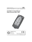
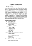
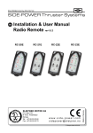
SLEIPNER MOTOR AS P.O. Box 519 N-1612 Fredrikstad Norway Tel: +47 69 30 00 60 Fax: +47 69 30 00 70 w w w. s i d e - p o w e r. c o m s i d e p o w e r @ s l e i p n e r. n o © Sleipner Motor AS 2015 Made in Norway Installation & User Manual Radio Remote RC-12E Contents Model range................................................................................................................................ 2 Technical specifications............................................................................................................... 3 Important precautions.................................................................................................................. 4 Receiver installation.................................................................................................................... 6 “Visual” wiring diagram................................................................................................................. 6 Programming additional transmitters............................................................................................ 7 Replacing the batteries................................................................................................................ 8 User precautions......................................................................................................................... 9 How to use the windlass remote................................................................................................ 10 Service Partners ....................................................................................................................... 12 Model range The radio remote control can control two independent windlasses. The receiver can receive the signals of up to four transmitters. Remote control kit (RC-12E) consists of: - Receiver: Part no. RCR-1E - Transmitter (incl. battery): Part no. RCT-12E - Holding bracket for transmitter unit: Part no. RC-HOLDER Additional transmitters can be ordered separatly: Part no. RCT-12E Antenna is available as spare part no. RC-ANT The transmitter and the receiver have the same factory preset code so no programming is necessary. The battery is already inserted in the transmitter. When additional transmitters are to be used, the receiver must be programmed again for all transmitters (please see programming section on page 7). We Sleipner Motor AS declare that this device complies with health and safety requirements according to the Directives EN301 489-3 V1.4.1:2002 EN301 489-1 V1.4.1:2008 IEC 60533:1999 EN300 220-1 V2.3.1:2010 EN300 220-2 V2.3.1:2010 Installation & User Manual, Radio Remote RC12E rev1_2 Page 2 Technical specifications Transmitter ModelRCT-12E Power feed 1 x 3V battery (type: CR2032) Frequency (MHz) 433,2 Operation temp. -10°C / +55°C HxWxD (mm) 95x48x25 Weight (g) 60 Receiver RCR-1E From windlass supply 433,2 -15°C / +55°C 89x68x33 135 Voltage: Load, max 8-30V 4A Operating range: 15m under normal operating conditions Important precautions • You should always install at least one original windlass panel. • Use the remote only for shorter periods of time to preserve transmitter battery life. Use the main control panel for longer runs of the windlass. • This manual is intended to support educated / experienced staff and is therefore not sufficient in all details for the correct installation. • When installed in boats approved or classified according to international or special national rules, the installer is responsible for following the demands in accordance with these regulations / classification rules. The instructions in this guide can not be guaranteed to comply with all different regulations / classification rules. • The transmitter and the receiver have the same factory preset code so no programming is necessary. When additional transmitters are to be used, the receiver must be programmed again for all transmitters (please see programming section on page 7). Installation & User Manual, Radio Remote RC12E rev1_2 Page 3 Receiver installation Prior to installation, it is important that the responsible installer reads this guide to ensure necessary acquaintance with this product. Warning! • Remote receiver power supply negative lead must be connected to the windlass negative lead. Caution! • Install the receiver minimum 1 meter (3ft) from high power cables and NMEA cables or other sources of electrical interference, i.e. navigation instruments, radio communication devices, electro motors and generators. • Install the receiver outside of shielded areas for radio signals, i.e. boxes made of steel or other material with shielding properties. • Install the receiver in a dry environment, with cables pointing downwards. (The receiver assembly is not waterproof.) • When additional transmitters are to be used, the receiver must be programmed again for all transmitters (please see programming section on page 7). • The receiver must have a separate power supply fitted with a 5 Amp fuse in the positive lead that has either a separate power switch or is shut of by the windlass main power switch. • Mount the receiver using the two screw holes (please see picture on page 6). If the receiver is mounted against a wall, use spacers between the receiver and the wall to avoid moisture in the receiver. Optimised installation (Fig. 1 - 3) • The receiver antenna must be placed in a vertical position minimum 1 meter (3ft) above sea level. • The receiver has antenna with SMA connector. If there is a problem with signal transferring, try to move the unit to a more optimised position or buy the antenna extension cable (RC-EXT) to relocate the antenna. - Above sea level - Away from sources of electrical interference. Note! Faulty installation will render all warranty given by Sleipner Motor AS void. Installation & User Manual, Radio Remote RC12E rev1_2 Page 4 Installation & User Manual, Radio Remote RC12E rev1_2 Page 5 Receiver installation Mount the receiver by using the 2 screwholes. If the receiver is mounted against a wall, use spacers between the receiver and the wall to avoid moisture in the receiver. Visual wiring diagram Installation & User Manual, Radio Remote RC12E rev1_2 Page 6 Programming additional receivers Push the Pair Button with a plastic stick The original transmitter and receiver have the same factory preset code so that no programming is necessary. When additional transmitters are to be used, the receiver must be programmed again for all transmitters. 1. Deactivate the receiver and all transmitters (press “OFF” on all transmitters). Turn off the main power switch for the windlass(es). 2. Turn on the power to the receiver. 3. Push the Pair Button on the receiver with a plastic stick (as shown above).The LED below the button will start to blink. 4. The receiver and transmitter are programmed by pressing both “ON” buttons on the transmitter. Within 5 seconds the LED will change from blinking to continous light when the programming signal is received. The transmitter is then ready to use. 5. Additional transmitters must be programmed according to step 3-4 when the receiver is in “Program mode”. You can pair up to 4 transmitters. 6. To clear all transmitters, hold Pair Button until LED blinks slow, continue to hold button pressed until LED blinks quick indictaing that a reset process is started. When LED is turned off, the reset process is completed, and the Pair button can be released. The LED will come on when the receiver has completed the reset process and is ready to be paired (Step 3-4) Installation & User Manual, Radio Remote RC12E rev1_2 Page 7 Replacing the battery Battery B A A B WARNING: Before working on the transmitter, deactivate the transmitter and the receiver (push “OFF” on the transmitter(s)) and turn off the power to the receiver as well as the windlass mainswitch. 1. Open the transmitter. 2. Take out the battery by inserting a screwdriver or similar between battery and holder at point A, and gently flip the battery out, taking care not damaging the battery grips at point B 3. Insert the new battery (Type CR2032, 3V - Brand name recommended). Be sure to insert the battery with the positive pole up diagonally into the battery holder, confirming that the edge of the battery is under the battery grips (B). Press the battery down until secured at point A. 4. Close the transmitter. Put the cover back in place, ensure that the rubber seal between remote upper and lower part is located correctly. Place the 3 screws (remember sealing washer) in their recessed holes and tighten. Installation & User Manual, Radio Remote RC12E rev1_2 Page 8 Important user precautions • Ensure that you know the location of the main battery switch that disconnects the windlass from all power sources (batteries) so that the windlass can be turned off in case of a malfunction. • How to activate the system: Turn on the main power source for the windlass system. Turn on the power to the receiver. The windlass system is then activated by pushing the two “ON” buttons on the transmitter (see page 10). To turn of the radio remote control press the “OFF” button on the transmitter for 2 sec. The LED below the Pair Button on the receiver will blink when a command signal is received. • Alarms: If transmitter/receiver is out of range, the transmitter will give an alarm sound. • The transmitter will automatically turn off after approx. 4 minutes of inactivity for safety reasons When using a single transmitter The system turns off automatically approx. 4 minutes after the last usage. When using more than one transmitter The system turns off automatically approx. 4 minutes after the last usage of the control unit that initially activated the system even if other control units have been operated in the meantime. The system is off even if these other control units still show the blinking LED on the transmitter. To use these transmitters, the system must be activated again by pushing the two “ON” buttons. • Remember to turn off the radio remote control by pushing the “OFF” button on the transmitter for 2 seconds and to turn off the power switch for the receiver when finished using your windlass Installation & User Manual, Radio Remote RC12E rev1_2 Page 9 Remote control “ON” Windlass 2 Windlass 1 Down Down Remote control “OFF” Auto-OFF appr. 4 min. Up Up Hold for 2 seconds How to use the remote control 1. Turn the main power switch for the windlass on. Turn on the power to the receiver. 2. Turn on the transmitter by pushing the transmitter’s two “ON” buttons. The remote system is now activated and then turns off automatically appr. 4 min. after the last usage (see page 9). 3. Use the remote only for shorter periods of time to preserve transmitter battery life. Use the main control panel for longer runs of the windlass. How to use the windlass Please consult your windlass manual for use and precautions. NB: Max. load on the windlass signal output is 4A! If the windlass requires more than 4A, use extra control relay (ref. llustration next page) Remote Control Deactivation Push the transmitter’s “OFF” button for two seconds (the remote control deactivates automatically after approx. 4 minutes after the last usage). Turn off the power switch for the receiver. Installation & User Manual, Radio Remote RC12E rev1_2 Page 10 Electric schematics Receiver Active antenna 2m antenna extension Insulation (Yellow) Red Blue Grey (Yellow) NOT IN USE +12/24V supply Max. load 4A NOT IN USE +12/24V supply Max. load 4A +12/24V supply for receiver Red Blue Grey Red Black Coil voltage depend of voltage supply. Output current of relay depend of load from winch. At least 3 time normal current. External relays for windlass requiring signal output over 4A Channel A Channel B 4-lead & 1-lead connector Windlass 1 Windlass 2 Installation & User Manual, Radio Remote RC12E rev1_2 Page 11 Worldwide sales and service www.side-power.com SLEIPNER MOTOR AS P.O. Box 519 N-1612 Fredrikstad Norway Tel: +47 69 30 00 60 Fax:+47 69 30 00 70 www.side-power.com [email protected]