1
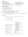
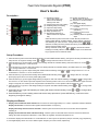
Power Factor Compensation Regulator (PFCR)
User’s Guide
Description :
c
25
d
e
f
g
24
23
22
l
(1). Operating indicator
Auto mode: Steady ON
Manual mode: Blinking
Setting mode: OFF
(2). Target power factor (PF) setting
(3). Switching delay time setting
(4). Capacitor steps setting
(5). Number of Phase setting
(6). Setup procedure key
(7). Number decrease key or
Manual switch-out capacitor
(8). Number increase key or
Manual switch-in capacitor key
(9). Enter key to confirm all setup
values
(10). LED digital display
(11). Indicator for abnormal PF or
no loads
(12). Indicator for PF in Lag
(Indicative)
(13). Indicator for PF in Lead
(Capacitive)
(14). Switching status of capacitor
steps
key
* Press SETUP key about 5 seconds to enter SETUP procedure for
setting COSØ, DELAY, STEPS, PHASE, Up/Low margin of target PF,
and Releasing PF value functions. Change values press
or
.
h
i
j
k
Selection of setting functions presses SETUP key. Press ENTER key to
exit and save the setting values.
key with AUTO indicator
* During automatic mode, press
or
blinking to manually switch in or out capacitor steps. Once release the
keys, regulator retums automatic mode.
Setup Procedure:
1. Press SETUP key about 5 seconds till AUTO indicator off and COSØ indicator blinking, then get into SETUP procedure for first
setup function to Target PF Setting. Press
or
to change value from IND 0.70 to CAP 0.70.
2. Press SETUP key to get into Switch-In Delay Time Setting with DELAY indicator blinking and CAP indicator on. Press
or
to change value from 1 to 995 seconds.
3. Press SETUP key to get into Switch-Out Delay Time Setting with DELAY indicator blinking, and IND indicator on. Press
or
to change value from 1 to 30 seconds.
4. Press SETUP key to get into Steps Setting with STEPS indicator blinking. Press
or
to change value from 1 to 7 for
model PFCR-7 and from 1 to 12 for model PFCR-12.
5. Press SETUP key to get into Phase Setting with PHASE indicator blinking. Press
or
change value to 1 for single
phase (1Ø) system and to 3 for three phase (3Ø) system.
6. Press SETUP key to get into Upper Margin Setting of Target PF with CAP indicator blinking. Press
to change value
or
from 0.00 to 0.10. This function prevents capacitors from overdoing switch in and out. If current PF fell between upper and lower
margin of target PF, the reactive power compensation is finished and no more capacitor will be switched in or out.
7. Press SETUP key to get into Lower Margin Setting of Target PF with IND indicator blinking. Press
or
to change value
from 0.00 to 0.10.
8. Press SETUP key to get into Releasing PF setting with Alarm indicator blinking. Press
or
to change value
from 0.00 to 0.60.
9. Press ENTER key to save setting values and exit the setup procedure. If press SETUP key, it will return to the
beginning for target PF setting.
Display and Status:
1. Display showed 000 with Alarm indicator on: it means low current (light loads) or no current. Capacitors will all be released.
Display showed 001: it means that the regulator detected failure on frequency.
Display alternately showed come PF and 002: it means system PF is less than 0.80 for 40 minutes with all capacitors
switching in.
Display showed 003 with Alarm indicator blinking: it means system is abnormal status and PF is lower than release PF
setting value with all capacitors switched in. In this status the regulator will switch all capacitors out.
2. Normal PF display with CAP indicator on or IND indicator on mean system in capacitive (Lead) or inductive (Lag), respectively.
3. LED digital display shows 60 or 50, it detects system frequency is 60Hz or 50Hz, respectively.
Default Setting:
1. Target PF (COS Ø) default IND 0.97
5. Phase defaults 3 phases
2. Switch-in delay time defaults 15 sec.
6. Upper margin of target PF defaults 0.03
3. Switch-out delay time defaults 15 sec.
7. Lower margin of target PF defaults 0.03
4. Number of steps default 7 steps for model PFCR-7
8. Release PF defaults 0.20
Number of steps default 12 steps for model PFCR-12
9. Switch sequence defaults circular
Terminals Description
Alarm :Contacts of abnormal PF alarm.
RS-485 :RS-485 communication input/output terminals.
L
﹕Terminals for secondary L signals of CT.
K
﹕Terminals for secondary K signals of CT.
Null
﹕NO use.
0V
﹕Connect L3 phase of power source with 2A fuse protected.
220V ﹕For 220 VAC system, connect L2 phase of power source with 2A fuse protected.
380V ﹕For 380 VAC system, connect L2 phase of power source with 2A fuse protected.
COM ﹕Connect L3 phase of power source with 6A fuse protected.
C1 to C7 (or C1 to C12)﹕Connects to one point of each magnetic contact coil, and another point of each magnetic contact coil
connects to L2 phase.
Connection