1
IN7
EXA3000 Installation Troubleshooting
EXA3000 Installation Troubleshooting
Goal
The goal of this skill set is to be able to troubleshoot possible EXA3000 installation
problems.
Objectives
Students should learn the following from this skill set:
♦ The safeties and interlocks on the EXA3000 and how to use this information for
troubleshooting.
♦ Possible power problems and solutions encountered during an installation.
♦ Possible heat exchanger problems and solutions encountered during an installation.
♦ Possible tester problems and solutions encountered during an installation.
♦ How to swap high speed cables to identify a bad cable.
♦ Possible acceptance program problems and solutions encountered during an
installation.
Rev 1
1
IN7
EXA3000 Installation Troubleshooting
In This Skill Set
______Information 1
______Information 2
______Information 3
______Information 4
2
Rev 1
IN7
EXA3000 Installation Troubleshooting
R
Resources
1. EXA3000 Test System
Installation Guide
http://www.san-jose.tt.slb.com/doc_page/soc.htm
or
T&T Home Page→San Jose Technical Info→Technical Publications→ SOC
Testers→ EXA3000 Installation Guide
2. EXA3000 Test System
Site Preparation Guide
http://www.san-jose.tt.slb.com/doc_page/soc.htm
or
T&T Home Page→San Jose Technical Info→Technical Publications→ SOC
Testers→ EXA3000 Site Preparation Guide
3. EXA3000 High Speed
Cabling Diagram
http://zapata.sanjose.tt.slb.com:922/cse_ix_cd/EXa3000_data/OPEN_ME_EXA3000.html
or
T&T Home Page→San Jose Technical Info→Technical Support
Information→ Test Systems→ CDROM→ Explore the EXA3000 Section→
EXA3000 High Speed Cabling Diagram
4. EXA3000
Harness/Cabling Block
Diagram
http://zapata.sanjose.tt.slb.com:922/cse_ix_cd/EXa3000_data/OPEN_ME_EXA3000.html
or
T&T Home Page→San Jose Technical Info→Technical Support
Information→ Test Systems→ CDROM→ Explore the EXA3000 Section→
EXA3000 Harness/Cabling Block Diagram
5. ITS 9000 Heat
Exchanger Schematic
http://zapata.sanjose.tt.slb.com:922/cse_ix_cd/IX_CD_data/OPEN_ME_FRIST_page_IX.html
or
T&T Home Page→San Jose Technical Info→Technical Support
Information→ Test Systems→ CDROM→ Explore the IX Section→ Heat
exchanger schematics
Rev 1
3
IN7
EXA3000 Installation Troubleshooting
6. Integrated Heat
Exchanger Manual
http://www.san-jose.tt.slb.com/doc_page/soc.htm
or
T&T Home Page→San Jose Technical Info→Technical Publications→ SOC
Testers→ EXA2000/EXA3000 Heat Exchanger Manual
4
Rev 1
IN7
EXA3000 Installation Troubleshooting
Information 1
System Safeties and Interlocks
The system has a series of safeties and interlocks providing equipment and personal
protection. These safeties are both hardware and software.
This section contains explanations and actions that can be used for debugging purposes
regarding the safeties and interlocks in the EXA3000 test system. The next section will
deal with power up problems, and knowledge of this information will be helpful at that time.
The interaction between the various safeties and interlocks can be seen in the following
documentation, and can be accessed in the Resources section.
♦ EXA3000 Test System Site Preparation Guide-EMO Schematic
♦ EXA3000 Harness/Cabling Block Diagram
♦ ITS 9000IX/KX Heat Exchanger Schematic
♦ Integrated Heat Exchanger Manual
Power Conditioner
The power conditioner for the EXA3000 system is a 60 KVA, 90 KVA, or 130 KVA unit with
the following safety features:
♦ The power conditioner has interlock switches to force an Emergency Machine Off
(EMO) condition if a service panel is removed.
♦ Thermal sensors inside the unit force an EMO condition if the temperature of the
transformer core exceeds vendor recommendations.
♦ The input circuit breaker is Under-Voltage (UV) controlled. Removing the 24 volts DC
from the UV unit forces the circuit breaker to trip into the off position.
♦ The input circuit breaker is lockable in the off position.
♦ The power conditioner generates an EMO voltage of 24 volts DC. Both the AC inputs
and the DC outputs are fused.
Rev 1
5
IN7
EXA3000 Installation Troubleshooting
Heat Exchanger
The heat exchanger provided with the EXA3000 system is a common base unit integrated
into the system mainframe. The AC power and control cables are internal to the system.
The heat exchanger’s safety features are:
Coolant Pump
The overload on the coolant pump motor trips if the motor is in an overloaded condition.
Normally this does not occur. The overload condition must exceed the overload adjustment
for an extended period of time.
To reset the pump motor in an overload condition, allow the motor to cool down and then
press the manual reset button on the overload unit.
Coolant Pressure Switch
The coolant pressure switch protects the liquid-cooled portion of the system in the event of
pressure loss by removing the DC ENABLE signal, which trips the power conditioner
output breakers CB2 and CB3, removing power to the liquid-cooled portion of the system.
Water Sensor
The water sensor, which is a float switch designated S9, is located in the bottom tray in
the heat exchanger. It detects the presence of water in the tray. When S9 opens, it breaks
the EMO loop and causes a system EMO.
Coolant Reservoir
The holding tank has two floats inside that monitor the coolant level.
♦ The first float warns if the coolant level is low. Two amber lights come on. One is
located on the face of the heat exchanger control panel and the other is on top of the
heat exchanger.
♦ The second float indicates that the holding tank is empty and stops the coolant pump.
The DC ENABLE signal is removed, which trips the power conditioner output breakers
CB2 and CB3, removing the power to the liquid-cooled portion of the system.
6
Rev 1
IN7
EXA3000 Installation Troubleshooting
Heat Exchanger 24 Volts AC
Inside the heat exchanger, the transformer TR-1 supplies a 24-volt AC signal. The primary
input voltage for TR-1 is 208 volts AC, with a secondary output voltage of 24 volts AC. The
transformer is rated at 100 VA.
Both of the inputs and the output of TR-1 are fused. The input fuses, F1 and F2, are 2
amp, 600 volt AC fuses. The output fuse, F3, is a 5 amp, 32-volt AC fuse.
Room Sensor
A room sensor is located next to the system’s main AC panel. This sensor is connected to
the heat exchanger controller and provides information about room temperature and
humidity. From these two values, a room dew point calculation is made.
♦ If the dew point exceeds 57 degrees Fahrenheit, or 13.9 degrees Celsius, the coolant
operating temperature changes to 65 degrees Fahrenheit, or 18.3 degrees Celsius.
♦ If the dew point rises above 63 degrees Fahrenheit, or 17.2 degrees Celsius, the
liquid-cooled portion of the system is turned off to prevent condensation.
Heat Exchanger Controller
The heat exchanger controller is programmed to maintain proper coolant temperatures.
Table 1 shows the temperatures of the different control points and their resulting actions.
Figure 1 is a graph of the normal operating set point operational sequence.
To convert Celsius (°C) to Fahrenheit (°F):
TF =
9
T C + 32
5
To convert Fahrenheit (°F) to Celsius (°C):
TC =
Rev 1
5
(T F – 32)
9
7
IN7
EXA3000 Installation Troubleshooting
Table 1:
Temp
(°° F)
95
89.6
80.6
68
66.02
Temp
(°° C)
35
32
27
20
18.9
66.92
19.4
64.94
18.3
62.96
17.2
62.96
17.2
61.88
16.6
59.9
15.5
57.92
14.4
Controller Temperatures for Heat Exchanger Operations
Purpose
Room high temp limit
High temp ALARM
High temp ALARM
Power down cooling
Chiller temp OK
High temp warning in high
coolant temp mode
High coolant temp mode
Low temp warning in high
coolant mode
Humidity-2 sensor
High temp warning in normal
coolant temp mode
Normal coolant temp mode
Low temp warning in normal
coolant temp mode
Humidity-1 sensor
Action
Cooling unit off
Cooling unit off in manual mode
Cooling unit off in auto mode
DC ENABLE off
DC ENABLE on
Blink light
Blink light
Cooling unit off
Blink light
Blink light
If dew point is < 57.2 °F, or 13.9
°C, then the set point is the
normal coolant temp of 59.9 °F,
or 15.5 °C.
57.2
13.9
If dew point is > 57.2 °F, or 13.9
°C, then the set point is the high
coolant temp of 64.94 °F, or 18.3
°C.
Low
temp
ALARM
Cooling unit off
55.4
13
Alarm Conditions - Auto Mode
room temp > 95 °F, or 30.6 °C
fluid temp > 80 °F, or 26.7 °C
fluid reservoir empty
fluid temp < 55 °F, or 19.2 °C
dew point is > 63 °F, or 17.2 °C
fluid pressure went low > 8 seconds
Alarm Conditions -Manual Mode
fluid temp > 90 °F, or 32.2 °C
fluid reservoir empty, with digital input DI7 high
fluid temp < 55 °F, or 19.2 °C
8
Rev 1
IN7
EXA3000 Installation Troubleshooting
Figure 1:
Heat Exchanger Normal Operating Set Point Operational Sequence
The SSC display is located on the heat exchanger’s internal service panel. Table 2 shows
the heat exchanger’s status signals that are sent to the SSC. In addition to providing four
inputs to the SSC, the heat exchanger receives a SYSTEM GOOD signal from the SSC.
The SYSTEM GOOD signal is provided as a digital input to the controller and is used to
turn the green SYSTEM GOOD light on and off on the user interface panel. The amber
CHECK SYSTEM light is on when the SYSTEM GOOD light is off.
Table 2:
Status Signals
Rev 1
Heat Exchanger Status Signals
Meaning
CHILLER_OK signal low
Chiller status is good
60/65 set point signal low
Control coolant at low set point
+/- degree set point signal low
Coolant less than 2 °F from set point
Coolant low signal low
Holding tank level is OK
9
IN7
EXA3000 Installation Troubleshooting
System Status Controller (SSC)
The SSC is located inside the mainframe and monitors voltages and temperatures internal
to the system. All DC voltages are monitored on a per cage basis. The high speed bay
boards and the PEC cards have over-temperature monitoring. All boards in the card cage
are powered off when a single board in that card cage indicates an over-temperature
condition.
♦ If a monitored voltage goes above or below 10 percent of nominal, all of the DC
voltages to that card cage are inhibited, or turned off.
♦ If a monitored temperature on a pin slice or a pin electronics board is an excessive
temperature, all DC power to that card cage is turned off.
♦ The SSC turns the DC output on or off when requested using a PSU switch. When the
PSU switch is turned on, the SSC determines if conditions are proper to allow DC
power to be applied to that card cage. The PSU switch may be on but the DC power is
off. The SSC sequences the different voltages to the card cages on or off in a predetermined manner.
NOTE: If the SSC is not powered on, the liquid-cooled portion of the system cannot be
turned on.
Power Supplies
The power supplies have internal circuits that provide over current, over voltage, and overtemperature protection. Any of the above excessive conditions will cause the DC voltage to
be either removed due to a thermal or over voltage trip, or reduced due to an over current
condition.
The power supplies DC outputs are turned on under operator control using the PSU
switches. All power supplies have internal fans to cool internal components.
Manipulator
The manipulator movement is controlled by the operator and provides the following
safeties:
♦ If the loadboard is mounted and vacuum is on, all of the manipulator motor movements
are inhibited.
♦ A cable and spring system supports the testhead’s weight so that only a small force is
required to move the testhead.
♦ An overload sensor is a safety mechanism to stop the testhead movement if there is an
obstruction to the testhead movement in the vertical direction.
10
Rev 1
IN7
EXA3000 Installation Troubleshooting
EMO Circuit
The EMO circuit is powered from a 24 volt DC power source. The circuit is activated when
the on button on the power conditioner is pressed. As long as the relay is active, the main
input rotary circuit breaker on the power conditioner can be turned on.
The EMO circuit is intended to remove AC power under the following circumstances:
♦ Opening any of the power conditioner panels
♦ Someone presses an EMO button
♦ The heat exchanger detects water in the bottom of the bay
♦ The thermal sensors above the cages open due to excessive heat
Removing the EMO voltage removes the 24 volts DC from the main input rotary circuit
breaker and causes it to trip.
When the EMO circuit is on, it allows:
♦ The power conditioner’s main input rotary circuit breaker to be turned on.
♦ Output breakers CB2 and CB3 at the power conditioner to be turned on, if the smoke
detector does not activate.
♦ All circuit breakers that control the liquid-cooled portion of the system to be turned on,
if the smoke detector does not activate.
Rev 1
11
IN7
EXA3000 Installation Troubleshooting
Undervoltage (UV) Trip Circuit
The EXA3000 UV trip and EMO circuits are different. While both circuits use under voltage
trip modules to turn off circuit breakers, their functions and purpose in the system are
different.
The UV trip circuit provides a method to remove AC power from the liquid-cooled portion of
the system in the event of:
♦ Heat exchanger or controller I/O failure
♦ SSC power supply failure
♦ Smoke detected in the system
The UV trip circuit voltage is generated when the EMO circuit is active. The 24 volt DC
voltage is routed through the heat exchanger and the SSC.
A different 24 volt AC, generated in the system’s main AC panel powers the smoke
detector units.
The following conditions must be met to activate the UV controlled circuit breakers.
♦ The heat exchanger must be in a condition for the green lamp on the service panel to
be on.
♦ The SSC must have DC power applied to the SSC alarm board.
♦ The smoke detectors have not detected smoke.
When the conditions above exist, the 24 volt DC voltage is available and allows the circuit
breakers to be turned on. The UV trip voltage controls output circuit breakers in the power
conditioner.
Smoke Detection Circuit
The EXA3000 has two smoke detectors. They are located in the top of each system
mainframe bay. The EMO voltage provides power to the smoke detectors, which sample
the exhaust air and cause an alarm condition if smoke is detected. The smoke detection
circuit is designed to prevent a fire from spreading beyond the system cabinet. If the
detectors sense smoke, the high powered portion of the system is turned off.
In an alarm condition, the relay that provides power to the under-voltage trip circuit
breakers is turned off. With the relay off, all AC power to the liquid-cooled section of the
system is also turned off.
To allow the system to power up again, the EMO circuit must be turned off and then back
on. After the EMO circuit has been turned back on, follow the normal system power up
procedure.
12
Rev 1
IN7
EXA3000 Installation Troubleshooting
Information 2
Troubleshooting Initial Power Up Problems
This section contains symptoms and recommended actions for some common initial power
up problems on the EXA3000 test system. They are not a comprehensive or step-by-step
troubleshooting guide, but a database for common initial power up problems.
NOTE: Feedback regarding new power up problems encountered more than once should
be forwarded to Technical Support for inclusion in the next skill set revision.
You should have the following three documents available when troubleshooting a power
up problem. The documentation can be accessed in the Resources section.
♦ EXA3000 Test System Site Preparation Guide-EMO Schematic
♦ EXA3000 Harness/Cabling Block Diagram
♦ ITS 9000IX/KX Heat Exchanger Schematic
Rev 1
13
IN7
EXA3000 Installation Troubleshooting
Input Power Problems
Problem
Possible Solutions
Input power to the power
conditioner incorrect
Contact customer facilities personnel to correct input power
from customers power source.
Input power at CB1 of the
system is incorrect.
If input power to the power conditioner is correct, contact
electrician or vendor to correct output power from power
conditioner.
Verify taps inside the power conditioner for correct
configuration.
Verify correct wire connection inside power conditioner.
EMO Problems
Problem
EMO circuit does not operate
correctly
Possible Solutions
Check for correct EMO voltage potentials at source and all
connection points.
Check for secure wire connections at all points
Heat Exchanger Monitoring Problems
The controller inside the heat exchanger bay monitors two important specifications:
♦ Coolant
♦ Room Air
If the limits are exceeded for coolant or internal system air, the controller turns off AC
power to the liquid-cooled section of the system. This keeps the under-voltage trip circuit
breakers on, and is not a system EMO.
Coolant Problems
Problem
Possible Solutions
With the system on, coolant is Coolant temperature is above 68 °F or below 55 °F
constantly being monitored
Coolant pressure is lower than 35 PSI.
for temperature and flow. The
Coolant supply tank is near empty
following conditions turn off
AC power to the liquid-cooled
section of the system.
14
Rev 1
IN7
EXA3000 Installation Troubleshooting
Heat exchanger will not turn
on at all
The pump has a current sensor. It is located above the AC
contactor. The buttons and small dial located on the unit can
identify this. If the red button has been tripped, pressing this
button in will reset the sensor.
The dial is set too low for the pump current. The correct value
is 27 amps or the Full Load Amperage (FLA) of the pump.
The heat exchanger turns on
for less then 15 seconds and
shuts off
Too much flow, input water is too cold, or a combination of both.
The heat exchanger core temperature may go below 50 °F so
when you turn on the heat exchanger the coolant temperature
goes below 50 °F. The heat exchanger turns off to prevent
damage caused by the coolant freezing and condensing. Once
the heat exchanger is turned off it will not turn on until the
temperature of the coolant goes above 51 °F. To determine if
you have this problem, monitor the temperature of the coolant
when you power up. If the temperature drops below 50 °F then
you have this problem. To enable the system to power up you
need to do one of two things. Both of these are temporary and
need to be set back to the original settings after the system is
powered on.
♦ Reduce the flow by partially closing the input chilled
water valve, normally located in the customer’s
chilled water plumping. Do not close it completely.
♦ Increase the input water temperature above 51 °F.
System powers down due to
coolant temperature being too
hot or cold. A/B modulating
valve not operating correctly.
Check the Y1 setting for the A/B modulating valve. For example,
if the reading is 50%, that equates to 5.0 volt controller output.
The formula is xx percent = x.x volts. Using a DVM, this 5 volt
measurement should be seen on analog output AO-1, pin 51, of
the controller and on one of the wires at the modulating motor. If
reading is not 5.0 volts, the controller could be bad. If reading is
5.0 volts, the modulating motor could be bad. Verify good wire
contacts at both ends. See Table 3.
Room Air Problems
Problem
System powers down due to
the room air temperature or
humidity
Rev 1
Possible Solutions
Check the air temperature setting, X3, and the humidity value
setting, X2, on the controller to see if the readings exceed room
temperature limits, X3 and A, or the calculated dew point limits,
Z3 and A. See Table 4 for information on the controller settings.
15
IN7
EXA3000 Installation Troubleshooting
Table 3:
Heat Exchanger Controller Inputs, Outputs, and Troubleshooting Information
Johnson Controller Input and Output Settings and Measurements
NOTE: On, Off, High or Low in bold indicates normal operating condition
Three Analog Inputs
Coolant temperature sensor
Between AI1, pin 2 and AIC, pin 3
Humidity sensor
Between AI2, pin 5 and AIC, pin 6
Room temperature sensor
Between AI3, pin 8 and AIC, pin 9
Eight Digital Inputs
Start
DI1, pin 31 is low, and DO4 is high
Reset
DI2, pin 33 is high, turns off outputs
Auto or manual
DI3, pin 35 is low in auto mode
Low or high
DI4, pin 37 is low in low position
Sys good
DI5, pin 39 is low, system good
Pressure OK
DI6, pin 41 is low, pressure ok
Fluid tank empty
DI7, pin 43 is low, tank is ok
Fluid tank low
DI8, pin 45 is low, tank is ok
One Analog Output
Modulating motor
AO1, pin 51 varies from 0 to 10 volts
Five Digital Outputs
Temp 65
DO3, pin 71 is high, DO2 turns off
CT-1
DO4, pin 77 is high, turns on pump
High dew
DO5, pin 73 is high, dew point > 63
Valve position
DO7, pin 75 is high, valve > 95 percent
Low pressure
DO8, pin 81 is high if DI6 is high
Eight Expansion Outputs
Chiller OK to SSC
DO1, Exp #1 R1 and NO is low
Set point status to SSC
DO2, Exp #1 R2 and NO is low, 60 F
< 2 degrees Fahrenheit to SSC
DO3, Exp #1 R3 and NO is low, <2 F
Coolant low to SSC
DO4, Exp #1 R4 and NO is low, fluid ok
Check system
DO5, Exp #2 R1 and NC is low
Information
LED Status
on
on
on
on
on
Notes:
Status to SSC
Status to SSC
Status to SSC
Status to SSC
Relay open
when on, sys
OK
Tank low
DO6, Exp #2 R2 and NC is low
on
Relay open
when on, fluid
OK
DC enable
DO7, Exp #2 R3 and NO is low
on
System good
DO8, Exp #2 R4 and NO is high
on
Relay closed
when on
Relay closed
when on
16
Rev 1
IN7
EXA3000 Installation Troubleshooting
Table 4:
Heat Exchanger Controller Keys, Settings, and Troubleshooting Information
Johnson Controller Keys and Settings
NOTE: On, Off, High or Low in bold indicates normal operating condition
X Key-Analog Inputs
1 = Coolant temperature
Fluid temp > 80 °F, or 27 °C, in auto or > 90 °F, or
32 °C, in manual, unit will shut off
2 = Humidity value in percent RH
Dew point is > 63 °F, or 17.2 °C, unit will shut off
3 = Room air temperature
Y Key-Digital Outputs
1 = Motor actuator position in percent
2 = N/A
3 = On, set point 65 °F, or 18.3 °C, selected
4 = On, pump contactor is on
5 = On, dew point is > 63 °F, or 17.2 °C
6 = N/A
7 = On, valve position is > 95 percent
8 = On, pressure fault detected
Room temp > 95 °F, or 35 °C, in auto, unit will
shut off
Displays % of valve stroke
Off, set point 60 °F, or 15.5 °C, selected
Off, pump contactor is off
Off, dew point is < 63 °F, or 17.2 °C
Off, valve position is < 95 percent
Off, pressure fault not detected
D Key-Digital Inputs (Input State)
1 = On, start relay is closed (low)
Off, start relay is open (high)
2 = On, reset button is closed (low)
3 = On, S2 in auto position (low)
4 = On, 65 °F operation (high)
5 = On, SSC sys good/true (low)
6 = On, fluid pressure is ok (low)
7 = On, tank is full (low)
8 = On, tank is not empty (low)
XT Key-Extension Outputs
11 = On, chiller ok, low signal to SSC
12 = On, 60 °F set point, low signal to SSC
13 = On, < 2 °F from set point, low signal to SSC
14 = On, tank is full, low signal to SSC
15 = On, system status is good
16 = On, tank is full
17 = On, DC enable is on
18 = On, System good is on
Off, reset button is open ( high)
Off, S2 in manual operation (high)
Off, S3 in 60 °F operation (low)
Off, SSC sys good/false (high)
Off, fluid pressure is low (high)
Off, tank is low (high)
Off, tank is empty (high)
Example: To view XT11, press Y, then XT
Off, chiller is not ready, high signal to SSC
Off, 65 °F set point, high signal to SSC
Off, > 2 °F from set point, high signal to SSC
Off, tank is low, high signal to SSC
Off, check system light is on
Off, tank low light is on
Off, DC enable is off
Off, System good is off
Rev 1
17
IN7
EXA3000 Installation Troubleshooting
Table 4:
Heat Exchanger Controller Keys, Settings, and Troubleshooting Information
(Continued)
X,Y, and Z Keys-Expansion Decode
Fluid Sensor Resistor Limits
Press X1, which is the coolant temperature,
then press the A button
Press the A button again
Room Relative Humidity (RH) Limits
Press X2, which is the room RH, then press the
A button
Press the A button again
Room Temperature Resistor Limits
Press X3, which is the room temperature, then
press the A button
Press the A button again
Calculated Dew Point to Switch to 65 ° F
Press Z3, then press the A button
Press the A button five more times to exit
Calculated Dew Point for Shutdown
Press Z4, then press the A button
Press the A button five more times to exit
18
NOTE: Spec is from 45 °F to 95 °F, LED on if > spec
Low limit of sensor resistor
High limit of sensor resistor
Zero percent RH
100 percent RH
NOTE: Spec is from 45 °F to 95 °F, LED on if > spec
Low is 45 °F
High is 95 °F
57 percent RH mode
Calculated dew point
63 percent RH mode
Calculated dew point
Rev 1
IN7
EXA3000 Installation Troubleshooting
AC Power Up Problems
Problem
Possible Solutions
With PSU switch off and the
power supply AC breaker on,
voltage is present at output of
power supply.
There should be no voltage on output of power supply. If
voltage is present, check the inhibit lines from the PSU board to
the power supply. The inhibit wire could be loose or
disconnected.
PSU board could be bad.
DC Power Up Problems
Problem
Short is measured at the
testhead motherboard
between two power supplies.
SSC will not operate correctly,
incorrect SSC messages, or
LEDs on alarm board flicker.
No output voltage present at
power supply or the
cage/testhead powers down
when the power supply AC
breaker and PSU switch are
on.
All liquid-cooled cages and
testhead will not remain
powered up.
Cannot power up the C and H
cages due to the tester’s
green DC enable light is off
and the CB2 and CB3 power
conditioner output breakers
cannot be set.
Cannot power cage/testhead
up after boards are installed.
Cage/testhead power stayed
on before boards were
installed.
Rev 1
Possible Solutions
This is normally an installation wiring error at one of the test
head power supplies.
Verify that the SSC power supply, CP1, has correct input and
output voltages. See Table 5 for SSC power supply information.
Verify power supply has all correct input voltages.
Verify power supply inhibit signal is correct.
Verify that the alarm board and PSU cables have not fallen off
and verify that they are in the correct locations. See Table 6,
Table 7, and Table 8 for details and Figure 2 and Figure 3 for
cable locations.
Verify that the DC enable light is on, and the power conditioner
output breakers CB2 and CB3 are on.
Cycle the power on the heat exchanger and the SSC alarm
board.
Verify the coolant temperature is within specification, which is
between 58 °F, or 14.4 °C, and 62 °F, or 16.6 °C. The
customer’s chilled water temperature may be out of spec due to
various facility reasons.
Remove boards from the cage to see if cage stays powered on.
If it does, one or more boards could be bad.
If cage still powers down, verify no backplane pins are bent.
Power supply could have gone bad.
19
IN7
EXA3000 Installation Troubleshooting
Table 5:
Circuit
Breaker
Power
Supply and
Module
SSC Power Supply Information
PSU Switch
Output
Voltage
(volts)
Spec
(mV)
Ripple
and Noise
(mV, p-p)
Output
Voltage For:
CB7
CPU (6)
CPU
5.2
+/- 104
50
Alarm board
CB7
CPU (7a)
CPU
15
+/- 300
50
Alarm board
CB7
CPU (7b)
CPU
-15
+/- 300
50
Alarm board
20
Rev 1
IN7
EXA3000 Installation Troubleshooting
Table 6:
Alarm Board Signals, Cable, and Connector Information (IX/KX)
Alarm Board Signals
+15 volt input power supply
Alarm Board
Signal To/From
Connector
J800
SSC PS41-1A (SSCP) (pins1,4,2,5)
-15 volt input power supply
+5.25 volt input power supply
J800
J801
SSC PS41-1B (SSCP) (pins1,4,2,5)
SSC PS41-1C (SSCP) (pins1,4,2,5)
AFFICHEUR
J811
SSC display
RS232 TXD, RXD
Control signals, bus 1
J818
J830
Force board and workstation
J900 PSU-C board
Control signals, bus 2
J831
TH1 monitoring, voltage and temperature, TH and
USER power supplies
J840
J900 PSU-H board
P77 on top ARM motherboard, to
P75 and P76 on testhead
motherboard
TH1REF, DEW_TH1, C0-15, L0-39
TH2REF, DEW_TH2, C0-15, L0-39
TH2 monitoring, voltage and temperature
H1 cage monitoring of voltage, temp, DC-OK, C015, and L0-39
H2 cage monitoring of voltage, temp, DC-OK, C015, and L0-39
H3 cage monitoring of voltage, temp, DC-OK, C015, and L0-39
H4 cage monitoring of voltage, temp, DC-OK, C015, and L0-39
C cage monitoring of voltage, temp, DC-OK, C015, and L0-39
SS monitoring of voltage, temp, DC-OK, C0-15,
and L0-39
J841
J846
J845
DCSS cage monitoring
J880
DCSS2 monitoring (not used on IX/KX systems)
Status monitoring
Vacuum_Fail_TH1
Vacuum_Fail_TH2 (Not Used)
Warning
H cages HIGHVOL_INH/, which is the 320 volt DC
enable/disable signal
J885
J900
J905
J910
J915
Rev 1
J850
J24 H1 cage backplane monitor
J855
J24 H2 cage backplane monitor
J860
J24 H3 cage backplane monitor
J865
J24 H4 cage backplane monitor
J870
J24 C cage backplane monitor
J875
J920
J24 aux (kx) analog (ix) backplane
monitor
J524 DCSS1 L/H/V/UCDPS
backplane monitor
J524 DCSS2 backplane monitor
Cooling bay monitoring
Vacuum control
Vacuum control
J1 on all 320 volt DC power supplies
21
IN7
EXA3000 Installation Troubleshooting
Figure 2:
22
Alarm Board Layout, Part Number 794000701
Rev 1
IN7
EXA3000 Installation Troubleshooting
Table 7:
Controller Bay PSU Board Signals, Cable, and Connector Information (IX/KX)
External address, data, and control signals
PSU Board
Connector
J900
+5.25 volt input power supply
PSU_0_INHIBIT, DC_OK 0 to DC_OK 11
J901
J910
SSC power supply
Analog cage IX (not used)
PSU_1_INHIBIT, DC_OK 12 to DC_OK 23
J915
PSU_2_INHIBIT
J920
J10 on analog cage KX (not used)
J10 Cp3a, Cp4, Cp5 for KX or Cp3c,
3b3, 3a1 for IX
PSU_3_INHIBIT
PSU_4_INHIBIT
J925
J930
PSU_5_INHIBIT, DC_OK 24 to DC_OK 35
PSU_6_INHIBIT, DC_OK 36 to DC_OK 47
J935
J940
PSU_7_INHIBIT, DC_OK 48 to DC_OK 59
J945
PSU_8_INHIBIT
PSU_9_INHIBIT
PSU_10_INHIBIT
J950
J955
J960
C Bay PSU Board Signals
Signal To/From
Alarm board J830
Analog cage IX (not used)
J10 UP1 power supply
J10 CP1 power supply and CPU
backplane
AUX cage inhibit KX
J10 DCSS power supply inhibit
PSU_11_INHIBIT
J965
NOTE: At this time, DC_OK is only used for CPU power supplies
Table 8:
H Bay PSU Board Signals, Cable, and Connector Information (IX/KX)
PSU Board
Connector
External address, data, and control signals
J900
+5.25 volt input power supply
J901
PSU_0_INHIBIT, DC_OK 0 to DC_OK 11
J910
PSU_1_INHIBIT, DC_OK 12 to DC_OK 23
J915
PSU_2_INHIBIT
J920
PSU_3_INHIBIT
J925
PSU_4_INHIBIT
J930
PSU_5_INHIBIT, DC_OK 24 to DC_OK 35
J935
PSU_6_INHIBIT, DC_OK 36 to DC_OK 47
J940
PSU_7_INHIBIT, DC_OK 48 to DC_OK 59
J945
PSU_8_INHIBIT
J950
PSU_9_INHIBIT
J955
PSU_10_INHIBIT
J960
PSU_11_INHIBIT
J965
NOTE: At this time, DC_OK is only used for CPU power supplies
H Bay PSU Board Signals
Rev 1
Signal To/From
Alarm board J831
SSC power supply
H2 cage power supply inhibit
H1 cage power supply inhibit
H4 cage power supply inhibit
Testhead 2
Testhead 1 power supply inhibit
H3 cage power supply inhibit
23
IN7
EXA3000 Installation Troubleshooting
Figure 3:
24
PSU Board Layout, Part Number 794000702
Rev 1
IN7
EXA3000 Installation Troubleshooting
Information 3
Troubleshooting Tester Problems
This section contains symptoms and recommended actions for some common initial tester
problems on the EXA3000 test system. They are not a comprehensive or step-by-step
troubleshooting guide, but a database for common tester problems.
NOTE: Feedback regarding new tester problems encountered more than once should be
forwarded to Technical Support for inclusion in the next skill set revision.
Rev 1
25
IN7
EXA3000 Installation Troubleshooting
Bus Problems
Problem
Possible Solutions
Intermittent bus problems
Check temperature on bus terminator board. If it’s cold, there is
a problem. It should be warm. Check the crimp on the -5V wires
to the terminator boards at cages. They could be loose due to
shipment, de-cabling or cabling process. Also measure
resistors, from signal to ground, on backplane terminator board.
Should be 26 ohms, if measuring 50 ohms or higher, terminator
board is bad.
Bus errors
If bus in inoperable, check for missing major bus signals by
doing the following:
In reg_talk, type the following: lp {ws 9920 4000} Using a
scope, check the resource test point on all HSI boards. The first
cage in the HS bus path that does not have a signal on this test
point is where the signal is getting lost. Either the cable
connection at the exit of the previous cage or the connection at
the input to the cage under question. Look carefully for bent
pins!
Move the HS VVI cables to take a cage out of the loop to see if it
is causing bus problems. Execute the failing bus event to see if
it still exists. If the problem has been resolved, the cause of the
failure is located in the eliminated H cage. If problem still exists,
you need to repeat this procedure for the remaining cages.
Figure 4 shows the VVI bus cable interconnection between the
VVI board, C cage, and H cages.
NOTE: VVI bus cable inputs/outputs on HSI boards in
the C and H cages:
Input is E-A1 to E-A11
Output is E-A128 to E-A138
NOTE: Bus cable part numbers, good to have as
spares:
VVI to HSI cable part number is 50903190
HSI long cable part number is 50903191
HSI short cable part number is 50903192
It may be necessary to scope signals to see the problem. Figure
5 shows the pin-out of the signals on the bus terminator board.
The boards are located on each side of the C and H cages.
This is a good place to probe. An extender tool for scope
probes, part number 09907846, can be used.
26
Rev 1
IN7
EXA3000 Installation Troubleshooting
Figure 4:
Pin
92
93
94
95
96
97
98
99
100
101
102
103
104
105
106
107
108
109
110
111
112
113
114
115
116
E
GRD.
GRD.
GRD.
GRD.
DB0
DB1
DB2
DB3
DB4
DB5
DB6
DB7
DB8
DB9
DB10
DB11
DB12
DB13
DB14
DB15
SO
S1
UWORD
TH2SEL
TXC
Figure 5:
Rev 1
EXA3000 VVI to HSI Bus Interface
D
GRD.
GRD.
GRD.
GRD.
GRD.
GRD.
GRD.
GRD.
GRD.
GRD.
GRD.
GRD.
GRD.
GRD.
GRD.
GRD.
GRD.
GRD.
GRD.
GRD.
GRD.
GRD.
GRD.
GRD.
GRD.
C
B
A
Bus Terminator Board Signal Location
27
IN7
EXA3000 Installation Troubleshooting
Cabling Checks
Before beginning any lengthy runs of diagnostics, run main_mem and ps_mem to check
the run-time cabling. Run th_diag, option 5, to check the testhead high speed cabling.
Mount a loadboard to test the vacuum. Run dc_diag to check the DC cabling.
When problems exist that could be cabling errors, review the pre-install checklist located in
the shipping documentation envelope. Check if the factory in removed any cables. This
has been added by the factory to inform the installation owner of any handling or removing
of cables due to re-dressing, replacements or modifications after power-down.
Th_diag Failures
Problem
Th_diag fails one pin
Possible Solutions
High speed cable installed incorrectly on H cage
Bent H cage backplane pin
Bad high speed cable from testhead to failing pin slice slot
Pin slice board bad
Digital pin electronics board bad
Th_diag fails in groups of
eight pins or more
Bent pin caltree board at ARM
Pin pushed out on caltree slot at ARM
High speed cables from testhead to failing pin slice slots
reversed
Pin slice board bad
Digital pin electronics board(s) bad
To verify if a high speed cable
from the testhead to H cage is
defective
28
Caltree board bad
Swap cables to see if problem moves. The cables are
interchangeable. See Table 9 for high speed cable signal
names, signal location and cable numbers.
Rev 1
IN7
EXA3000 Installation Troubleshooting
Table 9:
High Speed Cable Information from Testhead to H Cage Backplanes
High Speed Cable Backplane Connection Points from Pin Slice to PECs
Pin Slice
C
A
B
L
E
T
Y
P
E
A
C
A
B
L
E
#
B
C
A
B
L
E
#
P.
P
I
N
#
BACKPLANE
BACKPLANE
BACKPLANE
BACKPLANE
BACKPLANE
PIN
E
PIN
D
PIN
C
PIN
B
PIN
A
T
E
S
T
H
E
A
D
C
O
N
N
#
B
P
P
I
N
S
E-A
GND
DINH_Hx_P7/
GND
ACHI_Hx_P7/
GND_DHI
GND_DINH
GND_BCLO
GND_ACHI
DHI_Hx_P7
GND
BCLO_Hx_P7
GND
DHI_Hx_P7/
GND
BCLO_Hx_P7/
GND
P
I
N
6
21
J7 22
23
24
GND
ACHI_Hx_P6
GND
DINH_Hx_P6
GND
ACHI_Hx_P6/
GND
DINH_Hx_P6/
GND_BCLO
GND_ACHI
GND_DHI
GND_DINH
BCLO_Hx_P6
GND
DHI_Hx_P6
GND
BCLO_Hx_P6/
GND
DHI_Hx_P6/
GND
25
26
23
24
P
I
N
5
38
J6 39
40
41
GND
ACHI_Hx_P5/
GND
DINH_Hx_P5/
GND
ACHI_Hx_P5
GND
DINH_Hx_P5
GND_BCLO
GND_ACHI
GND_DHI
GND_DINH
BCLO_Hx_P5/
GND
DHI_Hx_P5/
GND
BCLO_Hx_P5
GND
DHI_Hx_P5
GND
29
30
27
28
P
I
N
4
42
J5 43
44
45
GND
DINH_Hx_P4/
GND
ACHI_Hx_P4/
GND
DINH_Hx_P4
GND
ACHI_Hx_P4
GND_DHI
GND_DINH
GND_BCLO
GND_ACHI
DHI_Hx_P4/
GND
BCLO_Hx_P4/
GND
DHI_Hx_P4
GND
BCLO_Hx_P4
GND
31
32
33
34
P
I
N
3
54
J4 55
56
57
GND
DINH_Hx_P3
GND
ACHI_Hx_P3
GND
DINH_Hx_P3/
GND
ACHI_Hx_P3/
GND_DHI
GND_DINH
GND_BCLO
GND_ACHI
DHI_Hx_P3
GND
BCLO_Hx_P3
GND
DHI_Hx_P3/
GND
BCLO_Hx_P3/
GND
35
36
37
38
2
P
I
N
2
75
J3 76
77
78
GND
ACHI_Hx_P2
GND
DINH_Hx_P2
GND
ACHI_Hx_P2/
GND
DINH_Hx_P2/
GND_BCLO
GND_ACHI
GND_DHI
GND_DINH
BCLO_Hx_P2
GND
DHI_Hx_P2
GND
BCLO_Hx_P2/
GND
DHI_Hx_P2/
GND
41
42
39
40
C
A
B
L
P
I
N
1
79
J2 80
81
82
GND
ACHI_Hx_P1/
GND
DINH_Hx_P1/
GND
ACHI_Hx_P1
GND
DINH_Hx_P1
GND_BCLO
GND_ACHI
GND_DHI
GND_DINH
BCLO_Hx_P1/
GND
DHI_Hx_P1/
GND
BCLO_Hx_P1
GND
DHI_Hx_P1
GND
45
46
43
44
P
I
N
0
91
J1 92
93
94
GND
DINH_Hx_P0/
GND
ACHI_Hx_P0/
GND
DINH_Hx_P0
GND
ACHI_Hx_P0
GND_DHI
GND_DINH
GND_BCLO
GND_ACHI
DHI_Hx_P0/
GND
BCLO_Hx_P0/
GND
DHI_Hx_P0
GND
BCLO_Hx_P0
GND
3
A
B.
GND
DINH_Hx_P7
GND
ACHI_Hx_P7
C
A
B
L
E
C
A
B
L
E
P
I
N
7
Testhead
2
3
4
5
C
A
B
L
E
4
B
P
I
N
S
L
I
C
E
Pin Slice Backplane
J8
J12
J11
J10
J9
E
1
Rev 1
19
20
21
22
47
48
49
50
29
IN7
EXA3000 Installation Troubleshooting
Vacuum Problems
Problem
Cannot achieve vacuum when
loadboard is on testhead and
the vacuum enable button is
pressed.
Possible Solutions
Verify vacuum is greater than 20 PSI. If not, check the
customer’s vacuum source.
Check for a pinched or twisted vacuum line
Check for leaks at seals on contactor board. Seals might be
damaged or have loose particles on them.
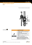
Loadboard EPROM Problems
Problem
Cannot read EEPROM on
loadboard when it is on the
testhead and the vacuum
enable button is pressed.
Possible Solutions
The serial I/O connections are connected to the calibration
EEPROM device. Figure 6 shows the schematic of the device. If
you have problems reading the loadboard EEPROM, check for
SCLK, SDATA, and VCC at the EEPROM. Normal values are:
SDATA on pin 5 is +5 volts
SCLK on pin 6 is 148 millivolts
GRD on pin 7 is 0 volts
VCC on pin 8 is +5 volts
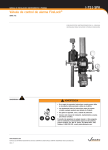
Check the purple cable under the contactor board carrying the
SCLK and SDATA signals.
The loadboard is marked SCLK and SDATA. These signals are
used to read and write information to the loadboard EEPROM.
They connect to the loadboard through the large pogo pins in
the outer ring of the contactor board. See Figure 7. These
signals come from the DCCAL board.
VCC is generated from the user power supply. It is wired directly
from the power supply to the contactor board.
30
Rev 1
IN7
EXA3000 Installation Troubleshooting
Figure 6:
Schematic of Loadboard EEPROM Device
Figure 7:
Rev 1
EEPROM Pogo Pin Location
31
IN7
EXA3000 Installation Troubleshooting
DC Subsystem Problems
Problem
Possible Solutions
Caltree_diag fails force &
sense resistance test.
If dc_diag and th_diag for DCCAL board passes, PMU cable can
be reversed at DCSS backplane even though connector is
keyed on the top and bottom. The wires should be on the right
side of the connector.
Dc_diag fails PMU and/or
DPSs
If the associated boards have been replaced and the failure still
exists, the problem could be loadboard related. Check the
External Interface Register (EIR) bits at the loadboard for a relay
not being selected or selected when it’s not supposed to. The
EIR bits come from the top and bottom ARM motherboard and
the caltrees, and go to the contactor board. Check for loose or
disconnected cabling. A total of 64 EIR bits are used to control
all possible relays. Figure 8 shows the pogo pin locations where
the EIR bits enter the loadboard.
Figure 8:
32
EIR Bit Pogo Pin Location
Rev 1
IN7
EXA3000 Installation Troubleshooting
Other Cabling Problems
Problem
Fails any alternate data
source or cable tests initially
after power up. For example,
ps_mem, ads_mem,
subr_mem, subr_diag,
apgx_ad_gen, timing_diag
cable tests, and so on.
Problem
No signal at the scope sync
jack
Rev 1
Possible Solutions
Verify that there are no cables disconnected or loose. Check on
the backplanes of the SMAB boards.
Ensure that there are no bent pins on backplanes. The factory
sometimes removes cables to re-dress them when decabling.
Possible Solutions
Check the scope sync cable connections made during
installation at the C cage
33
IN7
EXA3000 Installation Troubleshooting
Information 4
Troubleshooting Acceptance Problems
This section contains symptoms and recommended actions for some common acceptance
failures on the test system. They are not a comprehensive or step-by-step troubleshooting
guide, but a database for common acceptance problems.
NOTE: Feedback regarding new acceptance problems encountered more than once
should be forwarded to Technical Support for inclusion in the next skill set revision.
Loading and executing the acceptance programs is discussed in the EXA3000 Installation
Acceptance skill set.
Spechk_IXKX Problems
Problem
Possible Solutions
Single pin FAF or LAP failures
Rerun test to verify that the failure repeats. If it does, the most
common failures are pin slice or PEC boards.
Multiple pins fail due to graph
shifted to one side
Reduce pins to test and rerun spechk. For example, on a 352pin system, run pins 0-127. This will verify the H1 cage. Then
add H2 cage, running pins 0-255. If failure occurs, the problem
is in H2 cage.
Verify crossover calibration per Tech Bulletin 098
If STM_spechk fails.
STM spechk loadboard could have incorrect path length values
stored in the loadboard EEPROM. Calibrate the path lengths of
the loadboard by running the following calibration in a Force
board xterm.
Type: general_docal
Select option 15, Pin Pair Calibration.
Enter filename > /pathname/stm_lbrd_352.txt
34
Rev 1
IN7
EXA3000 Installation Troubleshooting
Pechk Problems
Problem
Possible Solutions
Single pin failure associated
with the PEC references.
The most common failure for a single pin is the digital PEC.
Multiple pin failure associated
with the PEC references.
Verify th_accuracy and caltree_diag pass. If so, the most
common failure is the force or sense caltree board or
connection.
Bad loadboard connection is also possible. Reseat loadboard
and verify or replace pogo pin.
If intermittent failures occur on various pins in the lower current
range, cycle th_accuracy using lowest current option. If
intermittent failures are seen, monitor the testhead power
supplies for noise with a scope while cycling the test. If noise or
ripple on testhead supplies exceed 50 millivolts, replace the
supply. Also check for good ground connection on supply.
PIO_validate Problems
Problem
Possible Solutions
This program checks out the
Verify the correct PH_TASK Pio_phi -D -h 1a is running.
system’s parallel port. If it fails:
Confirm that the cables are correct and secure at the tester and
test box.
Customer’s Acceptance Device Problems
Problem
Customer’s Acceptance
Device fails
Possible Solutions
Clean the loadboard and check the associated pogo pin. If
lbrd_dochar values are greater than 40ps, the loadboard is most
likely not making good contact with the pogo pin. Reseat the
loadboard and repeat test
Install another acceptance device and rerun test.
Replace the loadboard and rerun.
If failure still exists, run spechk or all_cal_diags.
For analog failures, pause or loop and use sysma to try the
other output relays on the APE. At this time, diagnostics do not
check all of them.
Rev 1
35