1
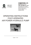
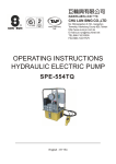
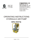
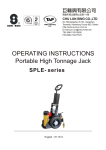
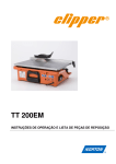
199
CHU LUN SING CO.,LTD
No.199,Gangshan N. Rd., Gangshan
Township, Kaohsiung County 820, Taiwan
http://www.sunrun.com.tw
E-mail:[email protected]
TEL:886-7-6210505
FAX:886-7-6217575
R
OPERATING INSTRUCTIONS
H FRAME PRESSES
English
E1~E3
Instructions for:
H Frame Presses
Models:SIP-100 series
1. SAFETY PRECAUTIONS
Fail to comply with the following cautions
and warnings could cause equipment
damage and personal injury.
IMPORTANT :Minimum age of the
operator must be 18 years The operator
must have read and understood all
instructions, safety issues, cautions and
warnings before starting to operate the
SUN RUN equipment. The operator is
responsible for this activity towards other
persons.
!
DANGER: NEVER set the relief valve to a
higher pressure than the maximum rated
pressure of the pump. Higher settings may
result in equipment damage and/ or personal
injury. Do not remove relief valve.
WARNING : The system operating pressure
must not exceed the pressure rating of the
lowest rated component in the system. Install
pressure gauges in the system to monitor
operating pressure. It is your window to what
is happening in the system.
WARNING : To avoid personal injury and
possible equipment damage, make sure all
hydraulic components withstand the
maximum pressure of 700 bar(10,000psi).
CAUTION: Avoid sharp bends and kinks
that will cause severe back-up pressure in
hoses. Bends and kinks lead to premature
hose failure.
WARNING: Always wear safety glasses.
The operator must take precaution against
injury due to failure the tool or workpiece.
DO NOT drop heavy objects on hose. A
sharp impact may cause internal damage to
hose wire strands. Applying pressure to a
damaged hose may cause it to rupture.
DANGER: To avoid personal injury
keep hands and feet away from cylinder
and workpiece during operation.
WARNING : Do not overload equipment.
Overloading cause equipment failure and
possible personal injury. The cylinders are
designed for a max. Pressure of 700 bar
(10,000psi).
R
!
IMPORTANT: Do not lift hydraulic
equipment by the hoses or couplers. Use
the carrying handle or other means of safe
transport.
WARNING: Immediately replace worn or
damaged parts with genuine SUN RUN
parts. SUN RUN parts are designed to fit
properly and withstand rated loads.
CAUTION : KEEP HYDRAULIC
EQUIPMENT AWAY FROM FLAMES AND
HEAT. Excessive heat will soften packings
and seals, resulting in fluid leaks. Heat also
weakens hose materials and packings. For
optimum performance do not expose
equipment to temperatures of 650C(1500F)
or higher. Protect hoses and cylinders from
weld spatter.
IMPORTANT: Hydraulic equipment must
only be serviced by a qualified hydraulic
technician. For repair service, contact the
SUN RUN Service Center in your area. To
protect your warranty, use only SUN RUN oil.
DANGER: Do not handle pressurized
hoses. Escaping oil under pressure can
penetrate the skin causing serious injury. If
oil is injected under the skin, see a doctor
immediately.
CHU LUN SING CO.,LTD
Page:E1
Instructions for:
H Frame Presses
Models:SIP-100 series
2.SPECIFICATION
2.1 If you use air or electric pump please check the detail at first
Air pump/ Air pressure : 7~10kgf/cm2
Electric Pump : Please check the data plate
2.2 Hydraulic oil: Aw46
A min
G
Pump Model
SIP-10EM
SIP-256EM
SIP-2514EM
SIP-30EM
SIP-506EM
SIP-5013EM
SIP-100EM
SIP-150EM
SIP-200EM
Motor
Oil cap.
0.5HP, 115V(60Hz) / 220V(50Hz),1PH
0.5HP, 115V(60Hz) / 220V(50Hz),1PH
1HP, 115V(60Hz) / 220V(50Hz),1PH
1HP, 115V(60Hz) / 220V(50Hz),1PH
0.5HP, 115V(60Hz) / 220V(50Hz),1PH
2HP, 115V(60Hz) / 220V(50Hz),1PH
2HP, 115V(60Hz) / 220V(50Hz),3PH
2HP, 115V(60Hz) / 220V(50Hz),3PH
3HP, 115V(60Hz) / 220V(50Hz),3PH
3000c.c
3000c.c
3000c.c
3000c.c
3000c.c
5gal.
5gal.
5gal.
5gal.
A max
K
N
D
C
M
L
E
J
F
Press Model
Number
Cap.
H-Frame Press Dimensions (mm)
Model No. Pump
Vertical Daylight
A
(max)
A
(min)
H
A
E
1016
62
H
A
E
1384
178
RSR-3014
H
A
E
1384
RSC-506
H
(tons)
SIP-RSC1010
SIP-RSR1010
SIP-RSC256
SIP-RSC2514
SIP-RSC308
SIP-RSR3014
10(101)
25(232)
30(295)
SIP-RSC506
RSC-1010
RSR-1010
RSC-256
RSC-2514
RSC-308
SIP-RSC5013
50(498) RSC-5013
SIP-RSR5013
RSR-5013
E
SIP-RSC10010
RSC-10010
H
SIP-RSR1006
100(933) RSR-1006
A
A
C
D
E
F
1187 127
473
632
1448
302
737
1029
178
1448
302
737
1233
179
1372
264
1080
178
1295
G
J
K
L
M
N
756
108
189
889
1321
102
762
133
272
673
1930
1029
102
762
133
272
673
1930
730
1086
127
914
184
365
781 1930
297
889
1295
171
914
222
441
842
1930
RSR-10013
E
SIP-RSR15013 150(1386) RSR-15013
E
1232
318
1384
254
1219
1706
232
1118
333
555
1213
2286
SIP-RSR20013 200(1995) RSR-20013
E
1232
318
1384
254
1219
1706
232
1118
333
555
1213
2286
SIP-RSR10013
H
Hand Pumps
R
A
Air Hydraulic Pumps
E
CHU LUN SING CO.,LTD
Electric Pumps
Page:E2
Instructions for:
H Frame Presses
Models:STP, SIP series
3. OPERATING
3.1 Bolster Adjustment:
A winch and cable assembly support the bolster when the support pins are not in place.
The following rules must be observed to prevent personal injury:
1. Keep hands, feet, etc. Out from under the bolster. Accidental slippage can result in personal injury.
2. To prevent slippage, all bolster support pins must be in place, and all cables slack, before placing
a work piece on the press bed or starting a pressing operation.
3. To prevent cable breakage, never raise or lower the bolster while it holds a load.
4. When raising or lowering the bolster, remove the work the work piece. Insert a support pin all the way
through the front and back uprights in the highest hole under the bolster that will not interfere with the
new bolster position. Remove your hands from the support pins after the pins are in place to avoid
personal injury should the bolster fall.
5. Inspect the entire length of the lifting cables at least every three months. Replace any cable that
appears frayed, worn, or crushed. The cables must run on the pulleys easily, and the pulleys must
be free to turn. Careful cable maintenance will help prevent cable breakage.
3.2 Assembly:
Remove banding from the press and shipping pallet, and remove all cartons. Stand the press upright.
Refer to the part list, and follow these instructions during the assembly of hydraulic components and
accessories.
1. Place the pump on the bracket. Thread four machine screws through the bracket into the bottom of
the pump reservoir.
2.Clean the threads on the threads on the hydraulic hose(s) and in the fittings. Assemble the hose(s)
to the pump.
3. Thread the other end of the hose(s) into the swivel fitting(s) on the ram.
4. Air can accumulate in the hydraulic system during initial setup or after prolonged use, causing the
ram to respond slowly or in an unstable manner. To remove the air, lay the ram on the floor. Extend
and retract the ram several times without putting a load on the system. Air will be released through
the pump reservoir.
5. Positioning the work bed:
A. Put a small amount of tension on the cable by cranking the winch up, taking weight off the pins.
This frees the pins in the end of the bolster next to the winch ( or right side of the press). Pull the
loose pins out.
B. Raise the other end of the bolster by pulling slightly on the handle until the other two pins are free.
C. Crank the winch for either up or down movement of the work bed. Reassemble the pins.
IMPORTANT:
The winch has a special friction brake for holding the bolster during positioning . The friction brake is
NOT designed to hold during a pressing operation, nor will it hold a work load during positioning.
WARNING:
To help prevent personal injury, the ram and mounting plate MUST have maximum thread engagement
to prevent the threads from stripping while the press is under full load.
R
CHU LUN SING CO.,LTD
Page:E3