1
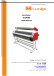
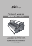
CHEMINSTRUMENTS
BENCHTOP LABORATORY LAMINATOR
MODEL LL-100 (A)
OPERATING INSTRUCTIONS
PRODUCT DESCRIPTION................................................................................................2
UNPACKING ......................................................................................................................3
ASSEMBLY ........................................................................................................................4
Key Components......................................................................................................6
OPERATION.......................................................................................................................7
Theory of Operation.................................................................................................7
Power Up ................................................................................................................7
Pressure Regulation .................................................................................................8
Flow Control Valves ................................................................................................8
Laminating Speed ....................................................................................................9
Continuous/Jog Switch ............................................................................................9
Laminating ...............................................................................................................9
MAINTENANCE ..............................................................................................................10
Tightening the Drive Coupling ..............................................................................11
Repairing Air Connections ....................................................................................11
Trouble Shooting ...................................................................................................12
WARRANTY ....................................................................................................................13
17
PRODUCT DESCRIPTION
Congratulations on the purchase of your new ChemInstruments
Instruments LL-100- (A)
Bench top Laboratory Laminator. Your new Laminator is lightweight, reliable, and
simple to use.
The unit has the following features:
x
Forward and reverse action of the drive roll.
x
Variable speed in either direction.
x
Continuous running and jog mode.
x
Precision crowned, 80 Durometer silicone rubber covered rolls.
x
Optional air piston movement of pressure roll.
x
Adjustable nip pressure.
x
24 inch laminating width.
x
Variable speed control from 1 to 13 feet per minute.
x
Available with optional 240VAC.
Photo 1 – Bench top Laboratory Laminator with air pistons
18
UNPACKING
ChemInstruments has made every effort to ensure that the LL-100- (A) arrives at your
location without damage. Carefully unpack the instrument and check for any damage that might
have occurred during shipment. If any damage did occur during transit, notify the carrier
immediately.
The ChemInstruments LL-100- (A) consists of the following parts:
x
The laminator frame, which includes the motor/drive mechanism.
x
An envelope with this manual and the power cord.
The Laminator is shipped with the pressure roll in the up position when supplied with the optional Gap
Adjusters; otherwise the pressure roll will be in the down position.
The power requirements are very simple. Plug the machine into a standard 120 VAC receptacle. A 2-amp fuse
protects the motor.
If the laminator is equipped with the optional air pistons (LL-100-A), it should be connected to a 90 – 100 PSI
air source. A standard ¼ inch male quick connect is located on the back of the machine.
Make sure all of these components are present before discarding the packaging material.
19
ASSEMBLY
Carefully remove the Bench top Laboratory Laminator from the packaging and set it on a
sturdy bench top. Due to its weight and size, two people should be used to move the LL-100(A). The space required for the unit is approximately 40" long x 11" deep x 18" high. As with
any precision piece of laboratory equipment, it is preferable to locate the LL-100-A in an area
where temperature and humidity are controlled to standard conditions (72 ± 2°F, 50 ± 5%
relative humidity).
Connect the power cord to its receptacle on the backside of the control cabinet at the far
left side when viewed from the rear. Complete the connection by inserting the male end of the
power cord into a convenient AC outlet. Notice that the on/off power switch is located directly
above the power cord receptacle. Connect an air hose to the ¼ inch male quick connect fitting
also located on the back of the control cabinet. (See Photo 2)
The ChemInstruments LL-100-A is now ready for use. Before proceeding with using the
LL-100-A, it is advisable to become familiar with the Key Components of the LL-100-A. These
Key Components and a brief description of their function follow in the next section.
20
KEY COMPONENTS (See Photos 2, 3 and 4)
x
POWER SWITCH is located on the back panel of the control cabinet directly above the power cord
connection.
x
PRESSURE ROLL the top roll supplying the laminating pressure.
x
DRIVEN ROLL the bottom roll connected to the motor and supplying the drive to the laminator.
x
SPEED CONTROL varies the speed of the drive roll. Speed range is from 1 to 13 feet per minute.
x
FORWARD/REVERSE SWITCH controls the direction of the bottom drive roll. The center position is the
off position.
x
CONTINUOUS/JOG SWITCH controls the bottom drive roll for continuous motion or intermittent motion
when the Jog button is pressed.
x
JOG BUTTON when the Continuous/Jog Switch is in the jog position this button engages the bottom drive roll
when pressed.
x
THUMBSCREWS control the laminating pressure at the nip.
x
NIP refers to the point of contact between the two laminating rolls.
P
AC Power Connection
Photo 2 – Control Cabinet Back Panel
21
MODEL LL-100-A only.
x
PRESSURE REGULATOR controls the air pressure being distributed to the optional air pistons.
x
PRESSURE GAUGE displays the air pressure being delivered to the air pistons after passing through the
Pressure Regulator.
x
FLOW CONTROL VALVES controls the flow of exhaust air from the pistons, which controls the speed of
the pressure roll moving up and down.
x
UP & DOWN SWITCH controls the position of the pressure roll.
Flow Control
Pressure Gauge
Nip
Speed Control
Continuous/Jog Switch
Forward/Reverse Switch
Jog Button
Up & Down Switch
Photo 3 – LL-100-A
22
OPERATION
THEORY OF OPERATION
There are two 24-inch wide precision crowned rubber coated rolls. The top pressure roll
is placed in contact with the bottom driven roll to form a nip. Material to be laminated is fed into
the nip allowing the pressure of the rolls to pull the material through. (See Photo 4) The
laminating pressure is regulated by either a set of adjustable thumbscrews or air cylinders
mounted on the bearing blocks at the end of the pressure roll. Switches mounted on the control
cabinet regulate the speed and direction of the bottom driven roll.
POWER UP
Turn on the master power switch located on the back panel of the control cabinet directly
above the power line receptacle. It is also necessary to open the air supply line valve if you have
the optional air cylinder model (LL-100-A).
Thumbscrews or optional
Air Cylinders (Shown)
Pressure Roll
Control Cabinet
Driven Roll
Photo 4 – LL-100-A
23
PRESSURE REGULATION
The desired laminating pressure must be determined and set prior to submitting material
to the laminator. The pressure on the nip can be adjusted by turning the adjusting thumbscrews
located at each end of the pressure roll. Turning the Thumbscrews clockwise will increase the
pressure and counter clockwise will decrease the pressure.
Model LL-100-A optional air pistons. Turning the Air Regulator knob, located on the
back of the control cabinet controls the pressure of the top roll at the nip. Turning the knob
clockwise will decrease the pressure and turning it counter clockwise will increase the air
pressure. The Air Gauge, located on the control cabinet, will display the current air pressure on
the top pressure roll when it is in the down laminating position.
FLOW CONTROL VALVES
The Flow Control Valves regulate the speed of the top pressure roll as it moves up and
down. Adjusting the valves in the following manner will regulate this movement. It may also be
necessary to adjust these valves to balance the movement of the air pistons in order for the top
pressure roll to travel evenly. If the speed of the two air pistons is not equal, one side of the top
pressure roll will move faster than the other side
The speed of the air pistons has been preset at the factory. These settings allow the top
pressure roll to move downward at a safe, slow speed, and move upward rapidly. Should it
become necessary to adjust these valves, use the following procedure.
x
The bottom valve controls the up speed and the top valve controls the down speed.
x
Turn the thumbscrews clockwise to go slower and counter clockwise to go faster.
x
After each adjustment move the top pressure roll up and down at least one time to
determine the affect and need for further adjustment.
x
Always maintain an even balance between the left and right Flow Control Valves to
avoid uneven movement of the top pressure roll when traveling up and down.
24
LAMINATING SPEED
The Speed Control switch controls the speed of the bottom Driven Roll. You can adjust
the speed of this roll between 1 foot per minute and 13 feet per minute. The laminator allows the
speed to be varied while the motor is running in either direction. This Speed Control switch also
allows you to turn the motor drive off, when turned to the 0 setting. It is important to note that
the indicating numbers on the speed control switch do not represent a measure of speed. They
are for reference only.
CONTINUOUS/JOG SWITCH
This switch allows you to operate the laminator in either of two modes. The Continuous
mode causes the bottom driven roll to run at the set speed continuously. The Jog mode activates
the Jog Button and allows the operator to move the driven roll at the set speed only when the Jog
Button is pressed. The flexibility made possible by these two modes of operation allows greater
precision when making laminations.
LAMINATING
After selecting the speed, pressure and direction of the laminator for your specific
material lamination, you need to control the material to be laminated in order to produce the best
possible lamination. The following is a list of aspects that will provide better control of your
lamination.
x
Always feed the material to the center of the rolls. This allows the crown of the rolls
to move air and wrinkles to the edges.
x
Maintain back tension on the material to eliminate wrinkles.
x
Use enough air pressure to provide a wrinkle free lamination.
x
Keep the two materials to be laminated apart until they come together at the nip.
x
Make sure the two materials are straight and aligned with each other before starting
the laminator.
x
Place the lead edge of your lamination on the center of the bottom roll then lower the
top roll and start the drive for the best results.
25
x
Maintain the proper speed to control the lamination without wrinkles.
MAINTENANCE
Maintaining the LL-100 (A) will provide many years of trouble free service. The
following is a list of actions that should be taken as needed.
x
On an annual basis it is advisable to lubricate the air piston shafts with lithium grease.
x
On occasion, the rollers may require cleaning. It is recommended that mineral spirits be
used when cleaning the surface of the rolls.
NOTE: Do not use toluene to clean the rubber surface of the rolls. Toluene will damage the
rubber surface. In addition, do not clean the rolls when they are rotating and make sure the
pressure Roll is in the up position before cleaning either of the rolls.
x
When idle, keep the rolls separate by moving the pressure Roll to the up position. This
helps prevent flat spots from developing on the rolls.
x
If the laminator is not to be used for an extended period of time, cover the rolls to protect
them from damage.
x
Before turning the air off on the optional Air Pistons, place a soft protective material
between the rolls.
x
If the laminator is equipped with the optional Gap Adjusters, they can be set to hold the
pressure roll in the up position when the air is turned off.
TIGHTENING THE DRIVE COUPLING
Should it be necessary to adjust the drive coupling between the motor shaft and the
bottom Driven Roll, the following procedure should be followed.
1. Remove the control panel by removing the four #6-32 screws holding the panel in place.
2. Carefully life the panel upward and toward the back of the cabinet. Be careful not to pull
any wires from their connection.
3. Locate the coupling joining the bottom roll shaft and the motor output shaft.
4. Line the coupling’s setscrews up with the flats on the shafts of the roll and motor.
26
5. To prevent further slippage, remove the setscrews and put a drop of removable Loctite
(or comparable product) on the setscrews before replacing them in the coupling.
6. Using a 3/32 allen key, tighten the two setscrews.
7. Replace the control pane, being careful not to pull or pinch any of the wires.
REPAIRING AIR CONNECTIONS
The air system in the Bench top laboratory laminator consists of valves, tube and fittings.
Should a leak develop it is likely to be at one of the tube and fitting connections. Determine
where the leak is located and follow the procedure below to affect a repair.
1. Disconnect the air supply from the laminator.
2. Remove the tubing at the connection that you have determined is leaking.
3. Cut the end of the tubing at right angles to its length just beyond the leak.
4. Make sure you have a square solid end to the tubing before proceeding.
5. Simply push the tubing onto the barbed fitting.
27
TROUBLE SHOOTING
Bottom Drive Roll does not turn
No power to motor
Check connections to power source
Fuse blown
Check incoming power fuse.
Replace with a 2-amp time delay
fuse.
Check switches
One or more of the switches is in the
off position
Motor shaft coupling loose.
Perform procedure on page 11
Top laminating roll does not turn
with bottom roll and material
Contact between rolls is absent
Make sure the top roll is in the down
position.
Increase the pressure to assure
contact between the top and bottom
rolls
Top laminating roll does not rise
when switched to up position
No air pressure
Check air connections and air
regulator for proper connection and
setting.
Check Flow Control Vales for
proper operation
Exhaust airflow is being restricted.
Top roll moves unevenly when be
raised and lowered
Air pressure is being exhausted
unevenly
Check Flow Control Valves on page
8
Lamination has air bubbles
Air trapped between layers being
laminated
Check for proper air pressure
Make sure material is in the center
of the rolls.
Make sure you have proper back
tension on laminate
Keep laminates apart till contact in
the nip.
Air system leaks
Tubing leak at connection
Perform procedure on page 11
Pressure roll will not lower
Pressure regulator is set to low
Adjust pressure regulator to a
minimum of 40 PSI
Flow control valves are closed
See Flow Control Valve section on
page 8
Air supply not connected
Connect machine to compressed air
line and make sure control valve is
opened.
No Air Pressure
28