1
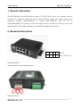
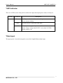
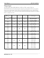
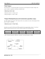
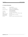
MSE
MIT-4X4GD-4
MIT-4X4GS-4
4 Ports Gigabit PoE Injector
USER’S MANUAL
MSTRONIC CO., LTD.
User’s Manual
MSE MIT-4X4GS/D-4
1. General Information
The MIT-4X4GD-4 and MIT-4X4GS-4 family is a DC/DC PoE (Power over Ethernet) Injector,
provide up to 4 different voltage DC input and four different voltage PoE output, output power
maximum
35W/port
(MIT-4X4GD-4)
or
2A/port
(MIT-4X4GS-4),
data
rate
can
be
10M/100M/1000M. The polarity of each PoE output can be reversed if you need to reverse the
output polarity. This manual will help you to install and setting the PoE injector.
2. Hardware Description
4
3
2
1
Data in
4
3
2
1
Data + Power out
Front panel detail
the port number is as the diagram shows.
Rear panel detail
2
MSTRONIC CO., LTD.
User’s Manual
MSE MIT-4X4GS/D-4
*LED Indicator
There are 4 LEDs on the front panel to indicate the input and output power status of each port.
LED
STATUS
1~4
Green
Description
A valid power device is detected on this port.
Active current is 80mA.
Red
No power device is detected on this port.
Off
No input power apply, or input source alarm.
Alarm voltage is larger than 58VDC, or less than 10.5VDC.
Alarm current is 2A.
*Data Input
The upper ports 1-4 on the front panel are used for Gigabit Ethernet data input.
3
MSTRONIC CO., LTD.
User’s Manual
MSE MIT-4X4GS/D-4
*Power Input
The input voltage range of MIT-4X4GS-4 is 12VDC to 57VDC, and 40~57VDC for
MIT-4X4GD-4, they are all common negative design, the green terminal (CON1) on rear panel is
used for power input wiring, it can be connected to maximum 4 different sources with 4 different
voltages, the jumper A, B, C, of JP1 on rear panel controls the input/output connection, its setting as
below. (1=jumper on, 0=off)
Jumper
Input
VIN1+
VIN1+
A
B
C
(1-2)
(1-3)
(1-4)
1
1
1
PoE 1/2/3/4=VIN1
(Factory setting)
1
1
0
VIN4+
VIN1+
PoE Output
PoE 1/2/3=VIN1
PoE 4=VIN4
1
0
1
PoE 1/2/4=VIN1
VIN3+
PoE 3=VIN3
VIN1+
PoE1/2=VIN1
VIN3+
1
0
0
VIN4+
VIN1+
PoE3=VIN3
PoE4=VIN4
0
1
1
PoE1/3/4=VIN1
VIN2+
PoE2=VIN2
VIN1+
PoE1/3=VIN1
VIN2+
0
1
0
PoE2=VIN2
VIN4+
PoE4=VIN4
VIN1+
PoE1/4=VIN1
VIN2+
0
0
1
PoE2=VIN2
VIN3+
PoE3=VIN3
VIN1+
PoE 1=VIN1
VIN2+
0
0
0
PoE 2=VIN2
VIN3+
PoE 3=VIN3
VIN4+
PoE 4=VIN4
4
MSTRONIC CO., LTD.
User’s Manual
MSE MIT-4X4GS/D-4
*PoE Output
The bottom ports 1-4 on the front panel are used for carry PoE output, the output voltage is the
same as input, no regulated. Normally as detailed below:
* Data pair A on line 1 and 2
* Data pair B on line 3 and 6
* Data pair C plus V+ on line 4 and 5
* Data pair D plus V- on line 7 and 8
*Output Polarity Reverse (for technician operation only)
The MIT-4X4GS-4 may deliver PoE output with reverse polarity. Just move related jumpers from
pin 1-2 to pin 2-3, and then
* Data pair C carry V- on line 4 and 5
* Data pair D carry V+ on line 7 and 8
Open the cover, the JP1~JP8 on the PCB responds for the output polarity of port 1~4, each two
jumpers should be paired moved to ensure the path enough for the through current.
Control port
JP1 & JP2
JP3 & JP4
JP5 & JP6
JP7 & JP8
Port 1
Port 2
Port 3
Port 4
* Pin1-2(short pin1 & pin2): RJ45 pair C (pin4 & 5) carry PoE positive voltage.
* Pin2-3(short pin2 & pin3): RJ45 pair C (pin4 & 5) carry PoE negative voltage.
5
MSTRONIC CO., LTD.
User’s Manual
MSE MIT-4X4GS/D-4
4. Technical Information
Data Rate
10M/100M/1000M
Input voltage:
12VDC to 57VDC (MIT-4X4GS-4)
40 VDC to 57VDC (MIT-4X4GD-4)
Maximum PoE power
Current limited – 2A/port (MIT-4X4GS-4)
35W/port (MIT-4X4GD-4)
Compliance
802.3af/at (MIT-4X4GD-4)
PoE protection
over-current, over/under voltage
LEDs:
Green-PD detect, Red-Power ready, Off-No power apply
Operating temperature
-40℃~ +75℃
Operation humidity
90% relative humidity, non-condensing
Storage temperature
-40℃~+85℃
Dimension
40mm(H) x118mm(W) x90mm(D) DIN RAIL Mountable
6
MSTRONIC CO., LTD.