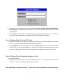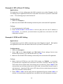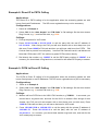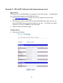
1
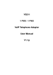
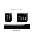
VS211
1 FXS / 1 FXO
SIP
VoIP Telephone Adaptor
User Manual
V2.1h
Quick Guide
Step 1: Broadband (ADSL/Cable Modem) Connections for VS211
A. Connect VS211 WAN port to ADSL NAT Router as the following connection.
B. Connect VS211 LAN port to Notebook PC LAN port using a Category 5 LAN cable.
C. Connect VS211 RJ11 PHONE port to a Telephone Set.
D. Connect VS211 RJ11 LINE port to a PSTN Telephone Line.
E. Connect 12VDC Power Adaptor. After power on, the POWER LED will be Green ON. In 5
seconds, the PHONE LED will start flashing 5 times and be ready for configurations.
F. The PHONE LED will be Green flashing for a successful SIP registration. Pick up the phone,
and it will be Green ON indicating VoIP mode.
G. Press 0* key, and the PHONE LED will be Yellow ON indicating PSTN mode.
H. Press #121# and #120# from the phone to listen to IVR and to check the DHCP status and the
LAN IP address (e.g. 192.168.123.1) for VS211. After the IP announcement, please hang up.
Figure A.
ADSL Connections with NAT Router for VS211
ADSL Modem
INTERNET
NAT Router
VS211 IP: 192.168.123.1
PC IP: 192.168.123.150
LAN
WAN
LINE
PSTN
PHONE
Step 2: Settings for VS211 from PC Web Browser
A. VS211 is defaulted at embedded NAT mode.
B. Press #120# from the phone to listen to IVR and take down the IP address (e.g. 192.168.123.1)
for VS211.
C. Enter the IP address from PC Web browser for configuration settings.
Example: Enter http://192.168.123.1 from IE Web browser to display login page.
D. Enter the user name and password into the blank field. The default settings are
Username: root
Password: test .
Click the “Login” button to enter for configurations.
2
E. You need to set up the following web configurations: Phone Settings, Network, SIP Settings,
NAT Settings for registration to a SIP server.
Remember to submit, save and reboot for new
configurations.
F. The PHONE LED will be Green flashing showing a successful registration in the SIP server.
For further detail configurations, please refer to the VoIP applications chapter.
Step 3: Making Point-To-Point SIP Calls
1. While the PHONE LED is flashing continuously showing a successful registration in the SIP
server, you may pick up the phone and should hear a dial tone.
2. Press 123456# to call the party with the number 123456 registered in the SIP server. Note # is
used to send out the call immediately. In a moment, you should hear the ring back tone, and
wait for the called party to answer. For more applications, please refer to the user manual
Step 4: Making Public Switching Telephone Calls
A. Pick up the phone.
B. Press 0* key for PSTN mode, and the PHONE LED will be Yellow ON, and you should hear a
dial tone.
Now you may dial any public phone number.
Note: Difficulties in configuring VS211? Please refer to the last chapter for trouble shootings.
3
TABLE OF CONTENTS
1.
2.
3.
4.
5.
6.
7.
8.
Introductions .........................................................................................................................6
Features................................................................................................................................6
Standard Compliances ..........................................................................................................7
Packing Contents..................................................................................................................7
LED Indicator ........................................................................................................................7
Installations & SIP Configurations .........................................................................................8
Default Reset by Telephone ..................................................................................................8
Configurations by Web Browser ............................................................................................9
Login VoIP Gateway..........................................................................................................................9
System Information ......................................................................................................................... 10
Phone Book Settings....................................................................................................................... 11
Phone Book ............................................................................................................................. 11
Phone Settings ............................................................................................................................... 12
Call Forward ............................................................................................................................ 12
SNTP....................................................................................................................................... 13
Volume .................................................................................................................................... 14
DND ........................................................................................................................................ 15
Auto Answer ............................................................................................................................ 15
Caller ID .................................................................................................................................. 16
Dial Plan .................................................................................................................................. 17
Flash Time............................................................................................................................... 19
Call Waiting.............................................................................................................................. 20
Call Transfer function ............................................................................................................... 21
T.38 (FAX)................................................................................................................................ 21
Hot Line ................................................................................................................................... 22
Alarm....................................................................................................................................... 23
Network .......................................................................................................................................... 23
Network Status......................................................................................................................... 23
WAN........................................................................................................................................ 24
LAN ......................................................................................................................................... 25
DDNS ...................................................................................................................................... 26
VLAN....................................................................................................................................... 28
DMZ ........................................................................................................................................ 29
Virtual Server........................................................................................................................... 30
L2TP........................................................................................................................................ 31
PPTP....................................................................................................................................... 32
SIP Settings.................................................................................................................................... 33
Service Domain ....................................................................................................................... 33
Port Settings ............................................................................................................................ 35
Codec Settings ........................................................................................................................ 36
Codec ID Settings.................................................................................................................... 37
DTMF Settings:........................................................................................................................ 38
Rport Settings.......................................................................................................................... 38
Other Settings.......................................................................................................................... 39
NAT Trans....................................................................................................................................... 40
STUN....................................................................................................................................... 40
Others............................................................................................................................................. 40
Auto Config.............................................................................................................................. 40
FXS & FXO Port ...................................................................................................................... 43
MAC Clone .............................................................................................................................. 43
Tone ........................................................................................................................................ 44
Advanced................................................................................................................................. 44
Status Log................................................................................................................................ 45
User Password ............................................................................................................................... 46
Save Changes ................................................................................................................................ 46
Update............................................................................................................................................ 47
New Firmware.......................................................................................................................... 47
Auto Update:............................................................................................................................ 50
4
Default Setting ......................................................................................................................... 54
Reboot............................................................................................................................................ 54
9. Configurations by Telephone & IVR.....................................................................................55
10. VoIP Applications Examples................................................................................................57
Example 1: Public Switched Telephone Network (PSTN) Calling/Answering .................................... 58
Example 2: SIP-to-SIP Calling/Answering........................................................................................ 58
Example 3: SIP to PSTN Calling ..................................................................................................... 59
Example 4: SIP to Direct IP Calling ................................................................................................. 60
Example 5: PSTN to SIP Calling ..................................................................................................... 60
Example 6: Direct IP to Direct IP Calling/Answering......................................................................... 61
Example 7: Direct IP to Direct IP Calling within NAT Router............................................................. 61
Example 8: Direct IP to PSTN Calling.............................................................................................. 62
Example 9: PSTN to Direct IP Calling.............................................................................................. 62
Example 10: 3-Way Conference Call, Call Transfer, Call Waiting, Hold ............................................ 63
Example 11: SIP-to-SIP Calling for http://www.inphonex.com/ ......................................................... 64
11. Trouble Shooting for Web Configurations............................................................................68
11.1. DO NOT HEAR DIAL TONE?.................................................................................................. 68
11.2. CAN NOT ACCESS WEB PAGE?........................................................................................... 68
11.3. ONLY ONE IP AVAILABLE FROM ADSL/CABLE SERVICE PROVIDER? ............................... 69
11.4. VOIP EXTENSION CALLS TO PSTN ARE NOT WORKING? ................................................. 70
5
1. Introductions
The VS211 is a 1-port FXS / 1-port FXO Telephone Adaptor (TA) with SIP Protocols for Voice over
IP (VoIP) applications. Connecting to the Internet and the PSTN line with an analog telephone set,
the VS211 can connect a VoIP call over the Internet with extension to the public switched
telephone line. VS211 provides one WAN port for Internet connections, one LAN port for Notebook
PC, and two RJ11 connectors for Phone (FXS) and PSTN (FXO). With an embedded NAT/DHCP
server, VS211 can be easily configured for different network diagrams by PC Web browser and
telephone set. This is very suitable for ITSP (Internet Telephony Service Providers) and SOHO
users to make 2-stage VoIP with PSTN extension calls.
Note that VS211 requires an IP address, a subnet mask, and its gateway Router IP address for its
own use to connect to Internet.
These three are available from your Internet service provider.
VS211 may enable PPPoE or DHCP features to automatically get an assigned dynamic IP from the
ITSP.
Please refer to Section 8 Configurations by Web browser for detailed information.
2. Features
The VS211 VoIP TA is equipped with two RJ11 connectors and two RJ45 connectors and is
featuring as the following
Three LED Indicators for VS211: POWER, PHONE, LAN
RJ45 x 2 for WAN and LAN ports + RJ11 x 2 for FXS and FXO ports
Configurations by Web Browser and Telephone
Embedded NAT/DHCP Server
PPPoE/DHCP Client for Dynamic IP plus NAT, DNS, and DDNS Clients
Support STUN server for NAT Traversal
Support registrations for up to 3 SIP Servers.
Hot Line Mode
Dial Plan Settings
T.38 FAX over IP
Interactive Voice Recording (IVR) for telephone IP status
Phone Book, Call Forward/Waiting, Call Transfer/Hold, and 3-Way Conference Calls
Auto Configurations by TFTP, HTTP, or FTP server
Remote Firmware Upgraded with HTTP or TFTP server by Web PC
Direct IP/URL Dial without SIP Proxy or Dial number via SIP server
Telephone features: Volume Adjustment, Phone book, and Flash
Out-Band DTMF (RFC 2833) / In-Band DTMF / Send DTMF SIP Info
6
3. Standard Compliances
The VS211 VoIP TA supports for the following standards
VoIP Protocol:
IETF RFC3261 and RFC 2543 for SIP
SIP Authentication:
IETF RFC2069 and RFC 2617 for MD5
Speech Codec:
ITU-T G.711, G.723, G.729A/B, VAD and CNG
Echo Cancellation:
ITU-T G.165/168
4. Packing Contents
Inside the package you should find:
(1) One VS211 SIP TA
(2) One AC to 12VDC/1A Power Adaptor
(3) One User Manual CD
Please check if the packing is damaged or any component is missing. If so, please contact your
distributor.
5. LED Indicator
On the front panel of VS211, there are three LED indicators as the following
POWER: “On” indicates the power is normal
PHONE:
“Green On” indicates the Phone is in use (off-hook) for VoIP call.
“Red On” indicates the PSTN Line is in use or ringing from incoming call.
“Yellow On” indicates the Phone and the PSTN Line are in use for PSTN call.
“Green Flashing” indicates successful registration at SIP server.
“Yellow Flashing” indicates PSTN incoming call with successful SIP registration.
LAN:
“On” indicates the WAN port is in Connection.
“Flashing” indicates the data activity of WAN port.
7
6. Installations & SIP Configurations
1. Connect VS211 RJ45 WAN port to ADSL Modem/Router using a Category 5 LAN cable.
2. Connect VS211 RJ45 LAN port to Notebook PC using a Category 5 LAN cable.
3. Connect VS211 RJ11 PHONE port to a Plain Old Telephone Set (POTS).
4. Connect VS211 RJ11 LINE port to a Public Switched Telephone Network (PSTN) line.
5. Connect the power adaptor (12VDC) to power on VS211, and the POWER LED will be ON.
6. The PHONE LED indicators will be OFF for about 5 seconds and start flashing for 5 times, and
remain OFF for VoIP configurations.
The LAN LED will be ON when RJ45 WAN port is
connected. If the PHONE LED keeps flashing, it indicates that VS211 has successfully
registered in the SIP server.
7. Pick up the phone, and the PHONE LED will be Green ON indicating VoIP mode. If you hear a
busy tone, please check if the WAN port is connected properly.
8. Press 0* keys to PSTN line. The PHONE LED will become Yellow ON and you should hear a
PSTN dial tone. If not, please check if the PSTN Line is connected.
9. Press #120# to check the assigned IP address for the VS211.
192.168.123.1.
The default IP address is
You may enter this IP address in IE Web browser from Notebook PC. Please
refer to Chapter 8 for web configurations.
10. Register VS211 into your SIP server. Please refer to VoIP applications examples of SIP
registrations.
After successful registration to the SIP server, the PHONE LED will start Green
flashing.
11. Pick up the phone, and you should hear a dial tone. Press 123456 to call the party with the
number 123456 registered in the SIP server. In a moment (5 seconds), you should hear a ring
back tone, and wait for answer. Note that you may press 123456# to dial out the number
immediately. Dialing without # will not dial out until the auto dial timer (default=5 seconds)
elapsed.
7. Default Reset by Telephone
VS211 provides an easy way to reset to factory defaults by using Telephone.
Pick up the phone and press #198# to reset back to factory defaults, and the VS211 will enter into
POWER ON cycle.
The PHONE LED indicators will be OFF for about 5 seconds and start
flashing for 5 times. The POWER LED then will be lit constantly, and the PHONE LED will be OFF.
If the PHONE LED keeps flashing, it indicates that VS211 has successfully registered in the SIP
server.
8
8. Configurations by Web Browser
Login VoIP Gateway
You may enter the IP address from PC Web browser to configure VS211. For example, enter
http://192.168.123.1 from IE web browser to display login page as follows.
8.1. Please enter the default IP address http://192.168.123.1 from PC Web browser.
The following Web page shall be displayed on PC.
If you have difficulties accessing the
Web page from the PC Web browser, the subnet IP of PC might be different from
192.168.123.xxx.
In this case, please refer to Chapter 11 for trouble shooting.
8.2. Please enter the username and password into the blank field. The default settings are:
Username: root
Password: test
8.3. Click the “Login” button will enter the management information page for system setup.
Note that whenever you change the setting in each Web page, please remember to click the
“Submit” button in the page, and click the “Save” button to save into the non-volatile memory
and click the “Reboot” button to activate the new settings.
9
System Information
8.4. You will see the system information such as firmware version, Codec, etc in this page.
8.5. You may click the button list at the left hand side to configure the VS211.
Model Name
Firmware Version
Codec Version
Protocol
Realm #1
Realm #2
Realm #3
MAC address
IP address/Netmask
Gateway
DNS
IP address/Netmask
Show device Model Name.
Device Risc version, eg: Tue Jan 16 11:28:32 2007
Device DSP version, eg: Wed Dec 20 17:28:06 2006
Call Status
Show device VoIP protocol.
Show the first registry information status
Show the second registry information status
Show the third registry information status
WAN Status
WAN port of MAC address
IP address/netmask
Default router IP address
DNS IP address
LAN Status
Current LAN port IP address/netmask
10
Phone Book Settings
Phone Book
8.6. You may add/delete Name (in numeric only) up to maximum 140 entries in Phone book list.
8.7. To add a phone name, you need to enter the position, the name, and the phone URL. When
you finished a new phone list, just click the “Add Phone” button.
8.8. To delete a phone name, please select the phone name then click “Delete Selected” button.
8.9. To delete all phone names, please click “Delete All” button.
8.10. After dialing a phone number, the TA will first match with the Name in the phone book.
matched, the TA will send out the corresponding URL.
If not, the dialed phone number will
be sent out.
8.11. Example 1:
Name: 101, URL: 192.168.1.100
Press 101# on telephone, and the phone at 192.168.1.100 will start ringing.
8.12. Example 2:
Name: 102, URL: [email protected]
Press 102# on telephone, and the TA will call the URL [email protected].
8.13. Example 3:
Name: 103, URL: 612345
Press 103# on telephone, and the TA will call the registered number 612345.
11
If
Phone Settings
8.14. The subpages are as follows; Call Forward, SNTP, Volume, DND, Auto Answer, Caller ID,
Dial Plan, Flash Time (or hook switch), Call Waiting, T.38 FAX over IP, Hot Line and Alarm
settings.
Call Forward
8.15. You can select the forward mode and enter the forward URL.
All Forward:
All incoming call will forward to the URL or PSTN you choose.
Busy Forward:
The incoming call will forward to the URL when the callee is busy.
No Answer Forward:
The incoming call will forward to the URLor PSTN when no answer.
8.16. You need to set the Time Out ring which will initiate No-Answer forwarding to the number you
choose.
When you finished the setting, please click the “Submit” button.
12
SNTP
8.17. You can setup the primary and second SNTP Server IP Address, to get the date/time
information.
You may also set the Time Zone, and how long need to synchronize again.
When you finished the setting, please click the “Submit” button.
13
Volume
8.18. You can setup the Handset Volume/Gain, PSTN-Out Volume, and PSTN-In Gain in this page.
Handset Volume is to set the volume hearing from the handset. PSTN-Out Volume is to set
the PSTN volume for you to hear. Handset Gain is to set the volume send out to the other
side’s handset. PSTN-In Gain is to set the volume send out to the other side’s handset.
14
DND
8.19. You can configure the DND (Do Not Disturb) setting to keep the phone silence. You can
choose either DND Always or a DND period.
8.20. DND Always: All incoming call will be blocked until this feature is disabled.
8.21. DND Period: Set a time period and the phone will be blocked during the time period. If the
time in “From” is greater than that in “To” time, the DND time will be from Day 1 to Day 2.
8.22. After you finished the setting, please click the “Submit” button.
Auto Answer
8.23. Auto Answer function can be used to relay calls between VoIP and PSTN. When the ring
count exceeds the number set in Auto Answer Counter, the Auto Answer function will be
activated when one of the 4 Auto Answer modes is chosen.
lP IN:
When the incoming call is from the Internet, the FXO port will answer with a PSTN
dial tone and wait the caller to dial another PSTN phone number.
FXO IN:
If the incoming call is from PSTN, the VS211 will answer with a dial tone and allow
caller to dial to another VoIP number.
Both:
Auto Answer function are enabled for Both IP IN and FXO IN.
Trunk Gateway:
When the incoming call is from the Internet, the FXO port will relay the
calling number directly to PSTN without intermediate dial tone.
call from VoIP.
15
This works only for incoming
PIN Code:
PIN Code is used to prevent from call piracy. If the PIN Code is enabled, you
will hear double beep tone after calling. The caller needs to enter the right PIN code and the
postfix “#” to get the PSTN dial tone.
Incorrect PIN Code will result in call disconnect.
Caller ID
8.24. You may show caller ID in your PSTN Phone or IP Phone by selecting “Yes” in Single Caller
ID, and the desired Caller ID option for either FSK or DTMF. After you finish the setting,
please click the “Submit” button.
16
Dial Plan
8.25. Dial plan and auto dial timer settings can be set in this page. The dial plan allows you to map
the dialing into an easy-to-remember phone number system. The auto dial timer specifies the
elapse time between the dialing digits. When Drop prefix is ON and the dialing prefix is
matched, the prefix will be dropped and replaced by the rule digits and followed by the rest of
dialing digits. When Drop prefix is OFF and the dialing prefix is matched, the rule digits will
be added before the dialing digits in accord with the settings
Routing to:
For selection of FXO, the call will be routed from FXS port to FXO port
(PSTN), when the dialing number matches the Routing rule.
routed to VoIP.
If not matched, the call will be
For selection of IP, the call will be routed from FXS port to VoIP if matched,
and vice versa.
Routing rule: This defines the routing rule from Telephone (FXS) to either PSTN line or
VoIP.
This is convenient for dial plan without using “0*” function key.
8.26. Symbol Representations:
Symbol
x or X
+
D
Example 1:
Representations
0,1,2,3,4,5,6,7,8,9
or
It “Drop” the matched dialing prefix number. This is for routing rule only.
Route to: FXO, Routing rule: D02+0800
a) Pressing 02xxxxxxxx will result in dialing out to PSTN port xxxxxxxx.
b) Pressing 0800xxxxxx will result in dialing out to PSTN port 0800xxxxxx.
c) Other dialing number will route to VoIP and follow the rules of Drop Prefix.
Example 2:
Drop Prefix: No, Replace rule 1: 002, 8613+8862
a) Pressing 8613xxx will result in dialing out 0028613xxx.
b) Pressing 8862xxx will result in dialing out 0028862xxx.
Example 3:
Drop Prefix: Yes, Replace rule 2: 006, 002+003+004+005+007+009
a) Pressing 002xxx will result in dialing out 006xxx.
b) Pressing 003xxxx will result in dialing out 006xxxx.
Example 4:
Drop Prefix: No, Replace rule 3: 009, 12
a) Pressing 12xxx will result in dialing out 00912xxx.
17
Example 5:
Drop Prefix: No, Replace rule 4: 007, 5xxx+35xx+21xx
a) Pressing 5xxx will result in dialing out 0075xxx.
b) Pressing 534 will result in dialing out 534 (not matched for the rest 3 digits).
c) Pressing 35xx will result in dialing out 00735xx.
d) Pressing 356 will result in dialing out 356 (not matched for the rest 2 digits).
e) Pressing 35668 will result in dialing out 35668 (not matched for the rest 2 digits).
Example 6:
Dial Now: *xx+#xx+11x+1[237]xx+xxxxxxxx
a) Pressing *00, *01, *02 .. *99 will result in dialing out the same *xx immediately.
b) Pressing #00, #01, #02 .. #99 will result in dialing out the same #xx immediately.
c) Pressing 110, 111, .. 119 will result in dialing out the same 11x immediately.
d) Pressing 1200, .. ,1299, 1300, ..,1399, 1700, .., 1799 will result in dialing out
the same 1[237]xx immediately.
e) Pressing 12345678 (8 digits) will result in dialing out 12345678 immediately. This implies
that the phone numbers with 9 or more digits are prohibited.
8.27. Auto Dial Timer: The inter-digit timer. Default is 5 seconds.
8.28. None SIP Server Mode : When SIP Settings > Service Domain were left blank (that means
no SIP registration available), you may enter a specific IP address (e.g. SIP gateway IP
address) in this field for all dialing numbers sending to this IP address.
when only SIP gateway is available.
This can be used
Note when at least one SIP server is successfully
registered in SIP settings, this will be automatically disabled.
8.29. When you finish the setting, please click the Submit button.
8.30. Click the Save button. The changes you have made will be saved and the VS211 will reboot
automatically.
18
Flash Time
8.31. You can set the flash time duration for the telephone flash key or hook switch in this page.
The telephone flash key is used to switch to the other phone line or HOLD, and is quite useful
for the 3-way conference call and the call waiting function. When you finish the setting,
please click the “Submit” button.
19
Notes:
1
2
Flash Signal Detect (MAX): Maximum Flash Hook duration (unit:10ms)
Flash Signal Detect (MIN): Minimum Flash Hook duration (unit:10ms)
Call Waiting
8.32. You can enable the call waiting function in this page.
It allows answering another coming
call by pressing flash key while holding the current call. You may switch back to previous call
by pressing flash key again. When you finish the setting, please click the “Submit” button.
20
Call Transfer function
The call transfer function allows users to answer an incoming call and to hold the current call by
pressing flash key, and then transfer the current call to the desired party by dialing the desired
party number ended with # key.
The call transfer function is exclusive with call waiting function.
You may enable call transfer function by disabling the call waiting function (#139#), or disable call
transfer function by enabling the call waiting function (#138#).
T.38 (FAX)
8.33. T.38 function can be used for FAX transmission over IP.
Note that T.38 function must be
enabled for both side of FAX over IP. You may enable or disable the T.38 function. T.38 Pass
through codec for u-Law or a-Law, and make sure your SIP server/gateway also supports this
T.38 function. When you finish the setting, please click the Submit button.
21
Hot Line
8.34. The Hot Line mode allows to making a direct call at the Phone Number or IP stored in this
page without dialing. Hot-Line Mode is very convenient for IP calling to Public Switching
Telephone Network (PSTN) number through FXO Gateway
8.35. When the Hot Line mode is enabled, you just pick up the phone and the VS211 will call the
party directly to the preset IP (or URL) address. The default for Hot Line mode is disabled.
8.36. You need to “Enable” and click the “Submit” button and reboot to activate the function.
Pick up the phone. In 1-2 seconds (default wait time), the VS211 will automatically call the preset
IP or phone number.
22
Alarm
8.37. You can configure the Alarm setting in this page..
Network
8.38. VS211 is equipped with an embedded NAT router between WAN and LAN ports to meet the
IP Network requirements.
If you have an external NAT router, then you may select Bridge
mode in WAN setting. Thus the two WAN and LAN Ethernet ports will be bridged and
transparent. Otherwise, you may select NAT mode to enable embedded NAT and go on
DDNS settings. The default is for NAT mode.
Network Status
8.39. You can check and show the current Network settings in this page.
Interface 0 is for WAN port Status and Interface 1 for LAN port Status.
23
WAN
8.40. The WAN setting is used to configure the WAN port connects to the ADSL Modem/Router.
8.41. The default setting is for NAT mode to enable the embedded NAT router between the WAN
port and LAN port. You may select Bridge Mode if you need NOT use the embedded NAT
router. When setting to Bridge Mode, only the WAN settings will get effective and the LAN
settings will be ignored.
8.42. There are three selections for WAN IP Type: Fixed IP, DHCP Client, and PPPoE modes. This
WAN setting is for the WAN port when set in NAT mode. The default is at DHCP Client.
8.43. For Fix IP Mode, please make sure the IP address. Net Mask, Gateway, and DNS settings
are suitable in your current network environment.
8.44. For PPPoE Mode, you have to enter correct username and password to get the IP address
from your Internet Service Provider.
8.45. When you finish the settings, please click the Submit button.
24
LAN
8.46. The default IP address is 192.168.123.1, with Net Mask 255.255.255.0., and DHCP Server
enabled. The range of IP addresses for DHCP is from 150 to 200.
8.47. Connect your PC to the LAN port, set your PC as DHCP mode, and the PC will automatically
get an IP address from the VS211.
8.48. When you finish the settings, please click the Submit button.
25
DDNS
8.49. You need to have a DDNS account before configuring the DDNS setting. Usually, most of the
VoIP applications are working with a SIP Proxy Server. Nonetheless, you may have a DDNS
account with a public IP address, and others can call you via the DDNS account. When you
finish the setting, please click the Submit button.
26
Example:
27
VLAN
8.50. The VLAN setting is for VoIP packets related to LAN port.
8.51. VLAN Packets: If you enable VLAN Packets and set the VID, User Priority, and CFI, then all
the incoming packets will be checked with the IP Address and the VID.
8.52. VID: Please set your VID in accordance with your service provider.
8.53. User Priority: Defines user priority with eight (2^3) priority levels. IEEE 802.1P defines the
operation for these 3 user priority bits. Usually, this will be defined by your service provider.
8.54. CFI: Canonical Format Indicator is always set to zero for Ethernet switches. CFI is used for
compatibility between Ethernet type network and Token Ring type network. If a frame
received at an Ethernet port has a CFI set to 1, then that frame should not be forwarded as it
is to an untagged port.
8.55. When you enable the first VLAN Packets and set the VID, User Priority, and CFI, then all the
incoming packets with the TA’s IP address and the same VID will be accept by the TA. If the
incoming packets with TA’s IP address but different VID then the packets will be discarded by
the TA. The Other incoming packets with different IP address will go through the WAN port to
the LAN port.
Notes:
When WAN port set to NAT Mode with VLAN enabled, please make sure the PC or network
device on LAN port must support the same VLAN function to pass through WAN port.
When WAN port set to Bridge Mode with VLAN enabled, the VLAN will only function on ATA.
The packets from LAN port will pass through WAN without VLAN function.
28
DMZ
8.56. The DMZ can be enabled/disabled and configured in this page
29
Virtual Server
8.57. The Virtual Server IP and Port numbers can be configured in this page.
30
L2TP
8.58. The Layer 2 Tunneling Protocol (L2TP) Server can be set ON/OFF in this page.
This L2TP
can be used to traverse the firewall when used with Virtual Private Network (VPN)
applications.
31
PPTP
8.59. The Point-to-Point Tunnel Protocol (PPTP) Server can be set ON/OFF in this page.
This
PPTP can be used to penetrate the firewall when used with Virtual Private Network (VPN)
applications.
32
SIP Settings
8.60. You can setup the Service Domain, Port Settngs, Codec Settings, RTP Setting, RPort Setting
and Other Settings for SIP Proxy Server registrations in this page.
Service Domain
8.61. You may register up to three SIP Servers for three Realms in the VS211. You can receive the
incoming calls from all the three SIP Servers.
For outgoing calls, you may select the
registration SIP server first, and then call the associated registration phone number.
8.62. To select SIP Server 1 (default), please pickup the phone, press 1*, then hangup.
8.63. To select SIP Server 2 (or 3), please pickup the phone, press 2* (or 3*), then hangup.
8.64. Click “Active” ON to enable the Service Domain, then enter the following items:
8.65. Display Name:
enter the name you want to display.
8.66. User Name:
enter the User Name given by your ITSP.
8.67. Register Name:
enter the Register Name given by your ITSP.
8.68. Register Password: enter the Register Password given by your ITSP.
8.69. Domain Server:
enter the Domain Server given by your ITSP.
8.70. Proxy Server:
enter the Proxy Server given by your ITSP.
8.71. Outbound Proxy:
enter the Outbound Proxy of ITSP. If not provided, you may skip this.
8.72. Register Period:
enter the Register Period in minute given by your ITSP.
8.73. When it shows “Registered” in the Register Status, it indicates a successful registration to
the ITSP, and the “PHONE” LED will start flashing. The VS211 is then ready for VoIP call
8.74. If you have more than one SIP account, please follow the steps to register to other ITSPs..
8.75. After you finish the setting, please click the “Submit” button.
33
34
Port Settings
8.76. You can setup the SIP and RTP port number in this page. Each ITSP provider might have
different SIP/RTP port setting, please refer to the ITSP to setup the port number correctly.
When you finish the setting, please click the “Submit” button.
RTP port are 5060 and 20000, respectively.
35
The defaults for SIP port and
Codec Settings
8.77. You can setup the Codec priority, RTP packet length, and VAD function in this page. You
need to follow the ITSP recommendations to setup these items.
36
Codec ID Settings
8.78. You can setup the Codec ID in this page. You need to follow the ITSP suggestion to setup
these items.
37
DTMF Settings:
8.79. You can setup the options for DTMF function in this page. The options include RFC2833
(Outband DTMF), Inband DTMF, and Send DTMF SIP info.
The default is set at Inband
DTMF. If you are making two-stage callings for extension to PSTN, you might need to select
Outband DTMF option.
Rport Settings
8.80. You can enable/disable the RPort in this page. To change this setting, please follow your
ITSP suggestions. When you finish the setting, please click the Submit button
38
Other Settings
8.81. You can setup the Hold by RFC and QoS in this page. To change these settings please
follows your ITSP information. When you finish the setting, please click the Submit button.
The QoS is used to set the voice packet priority. Higher value other than zero will get higher
priority for the voice packets in Internet. However, the QoS function still needs to cooperate
with the other Internet devices.
1
SIP Expire Time: 60 (15~86400 sec, 0=defined by Server).
2
Keep Alives Period: 60 (Default: 60, Range: 15 ~ 250sec) that is send keepalives
messages in the RTP stream to keep NAT open.
3
Jitter Buffer: 1 (Default: 1, Range: 0~250 packets)
4
SIP Server Type: General, Asterisk, BroadWorks, Nortel, Xener, Vodtel.
5
SIP VID: 0 (2~4094, 0: disabled). This VLAN ID is for SIP only through WAN.
RTP VID: 0 (2~4094, 0: disabled). This VLAN ID is for RTP voice packets.
39
NAT Trans
STUN
8.82. The STUN function must be enabled to work properly behind NAT when registered in SIP
server. You may enter the STUN server IP address and the STUN port number as shown in
the following example.
Others
8.83. You can setup Auto Config, FXO& FXS Port MAC Clone, Tone and Some Advanced Settings
and Status Log in this page
Auto Config
8.84. Auto Configuration function can be used to download the original configurations stored in the
TFTP, HTTP or FTP server.
This is useful for the new user to automatically download a
predefined configuration setting. Remember to click the “Submit” button and “Save” in the
Save Change section.
The VS211 will then reboot and automatically download the original
configurations from the TFTP or FTP server. Note that the TFTP download works only for
public IP address
40
TFTP Mode
41
FTP Mode
HTTP Mode
42
FXS & FXO Port
8.85. You may select the FXS and FXO impedence of the analog telephone by different countries
MAC Clone
8.86. The MAC Clone function is to clone the MAC when only one MAC is available from ITSP. This
is to share with the PC using the same MAC. When you finish settings, please click the
Submit button
43
Tone
8.87. .The Tone setting can be adjusted to generate Dial tone, Ring back tone, Ring tone,
Congestion tone, Call waiting tone and Busy tone for different countries. When you finish with
the settings, please click the Submit button.
Advanced
8.88. The advanced settings might be useful for some network requirements. The ICMP function is
to echo when someone ping this device. This can prevent from hacker attacking the device
by not echoing. When you finish the setting, please click the Submit button
1
IP Dialing format (P2P dialing): There are 3 options.
2
Type 1([email protected]), by default when you dial 192.168.1.100, VS211 will auto prefix
userip@ in your dialed IP address and send out to remote end.
3
Type 2 (x.x.x.), when you dialed 192.168.1.100, it will send 192.168.1.100 out to
remote end without appending anything.
4
Disable: disable IP dialing function.
5
Encryption Type: Must be disabled for standard SIP protocol. Please consult your
ITSP for encryption type when registered in ITSP.
6
Encryption Key: Special key for encryption need.
44
Status Log
8.89. You can check system status log
45
User Password
8.90. You may change the login name and password in this page.
Save Changes
8.91. You can save the changes you have made, and click the Save button. After clicking the
“Save” button, the VS211 will automatically save the new settings.
46
Update
New Firmware
8.92. VS211 provides two methods, HTTP or TFTP, to update new firmware as the following steps
HTTP is mostly used for firmware update by using local PC.
TFTP is used with TFTP server for firmwares stored in TFTP server.
1
Select the firmware code type, Risc or DSP code. (mostly for Risc code)
2
Click the “Browse” button to choose the updated file location for HTTP download, or
3
Select TFTP and enter the IP address of TFTP server for firmware download, then click
the “Update” button.
47
TFTP Mode
48
NOTE:
Do NOT power OFF the VS211 after clicking the “Select” button, or you may
damage the VS211.
The remote TFTP download works only for public IP address.
8.93. After clicking the “Update” button, the firmware list will be displayed from server to indicate
the available firmware for download
8.94. Select the new file you want to download to the VS211 then click the “Select” button
In 3 to 4 minutes, the PHONE LED indicators will start flashing 5 times to indicate successful
firmware update.
Then, you need to login again new IP address which is available from IVR
by pressing #120# from phone.
49
Auto Update:
8.95. Auto update function can be used to auto-update the firmware stored in the TFTP, HTTP or
FTP server per the schedule as the following settings:
8.96. Select the update method and enter the server IP address,
8.97. Click the “Submit” button to get auto-update effective.
Notes:
Check new Firmware:
Power on and Scheduling: Check new firmware when power on and in accord with schedule.
Must be manually updated.
Scheduling Only (default): Check in accord with schedule.
Scheduling (Date): Default at 14 days.
Scheduling (Time): Default at AM 00:00 – 05:59 randomly.
50
TFTP Mode
51
FTP Mode
52
HTTP Mode
53
Default Setting
8.98. You can restore the VS211 to factory default in this page. By clicking the “Restore” button, the
VS211 will restore to default and automatically restart again.
Reboot
8.99. You may click the Reboot button to restart, then VS211 will automatically reboot with the
stored configurations.
54
9. Configurations by Telephone & IVR
You can use telephone to configure and to check the status of VS211.
Note that the WAN port is
for WAN port of VS211, and the LAN port is for LAN port of VS211.
Group
IVR Action
Phone Command
Remarks
IVR will report the current TA local IP
address. Hang up while hearing end tone.
IVR will report if WAN DHCP in enabled or
disabled. Hang up while hearing end tone.
Status
Check TA LAN IP Address
#120#
Status
Check IP Type
#121#
Status
Check Phone Number
#122#
IVR will report registered phone number.
Status
Check Network Mask
#123#
IVR will report WAN network mask.
Status
Check Gateway IP Address #124#
IVR will report WAN Gateway IP address.
Status
Check Primary DNS Server
#125#
IP Address
IVR will report WAN Primary DNS Server IP
address.
Status
Check TA WAN IP Address #126#
IVR will report the TA WAN IP address.
Status
Check Firmware Version
Status
Set WAN interfaces Speed #129+[0-4]#
Setting
Set WAN DHCP client
Setting
Set WAN Static IP Address #112xxx*xxx*xxx*xxx#
Setting
Set WAN Network Mask
#113xxx*xxx*xxx*xxx#
Setting
Set Router IP Address
#114xxx*xxx*xxx*xxx#
Setting
Set Primary DNS Server
#115xxx*xxx*xxx*xxx#
Setting
Set Codec
#130+[1-8]#
Setting
Set Handset Gain
#131+[00~15]#
Ex: #13107# and default is 06
Setting
Set Handset Volume
#132+[00~12]#
Ex: #13209# and Default is 10
Setting
Auto Configure Mode
#150+[0~3]#
0: Disable, 1: TFTP mode 2: FTP mode
3 : HTTP mode
#128#
IVR will announce the firmware version.
0: Auto, 1: 100M Full, 2: 100M Half,
3: 10M Full, 4: 10M Half
#111#
This set WAN to DHCP Client mode.
55
Ex: #112061*066*159*009#
Note xxx must be 3 decimal digits.
This setting will disable DHCP Client.
Ex: #113255*255*255*000#
Note xxx must be 3 decimal digits and
Must set WAN Static IP first (#112).
Ex: #114061*066*159*254#
Note xxx must be 3 decimal digits and
Must set WAN Static IP first (#112).
Ex: #115159*168*001*001#
Note xxx must be 3 decimal digits and
Must set WAN Static IP first (#112).
1:G.711 u-Law,
2: G.711 a-Law,
3: G.723.1,
4: G.729a,
5: G.726-16K,
6: G.726-24K,
7: G.726-32K,
8: G.726-40K.
Group
IVR Action
Phone Command
Remarks
Setting
Enable Call Waiting
#138#
This will disable Call Transfer.
Setting
Disable Call Waiting
#139#
This will enable Call Transfer.
Setting
Unlock Keypad
#190#
You must unlock keypad first in order to
change settings by keypad.
Setting
Lock Keypad
#191#
Keypad can NOT be used for setting.
Setting
Reboot
#195#
After you hear “Option Successful,” hang-up
and TA will reboot automatically.
Setting
Factory Reset
#198#
TA will reset back to factory defaults.
WARNING: ALL “User-Changeable”
NONDEFAULT SETTINGS WILL BE LOST!
Setting
Blind Call Transfer
#510#xxxxxx#
Ex: #510#54321# transfer to 54321
Setting
Attendant Call Transfer
#511#xxxxxx#
Ex: #511#54321# transfer to 54321
Setting
3-Way Conference Call
#512#xxxxxx#
Ex: #512#54321# conference with 54321
Setting
Attendant Call Transfer to
#514#xxxxxxxx#
PSTN
Ex: #514#12345678# transfer to 12345678
from IP to PSTN Line.
0*
Switch to PSTN port, will hear dial tone of
PSTN Line.
Setting
1*
Select the First SIP server.
Setting
2*
Select the Second SIP server.
Setting
3*
Select the Third SIP server.
56
10. VoIP Applications Examples
You can use PC Web browser to configure VS211.
For example, enter http://192.168.123.1 from PC web browser.
A. ADSL Connections without NAT Router for VS211
ADSL Modem
WAN
INTERNET
LINE
PSTN
LAN
PHONE
B. ADSL Connections with NAT Router for VS211
ADSL Modem
INTERNET
NAT Router
WAN
LINE
PSTN
VS211 IP: 192.168.123.1
LAN
PHONE
57
Example 1: Public Switched Telephone Network (PSTN) Calling/Answering
Applications:
VS211 is default at the VoIP mode.
For PSTN calls, you may just pick up the phone, press
0* key, and dial directly to the PSTN number like a normal telephone.
Configurations:
1. Select “ON” for the “Auto Answer” in Phone settings.
2. Select a value for Auto Answer Ring Counter, and the default value is set at 3.
3. Click the “Submit” button.
Calling/Answering
4. Pick up the phone and press 0* key for PSTN mode, and you should hear a dial tone.
5. Press, e.g. 1234567, to call the PSTN party with 1234567. In a moment, you should hear
a ring back tone, and wait for the called PSTN party to answer.
6. When receiving PSTN incoming call, you must pick up the phone within 4 rings to answer,
otherwise the VoIP mode will answer automatically for IP extension call. Please refer to
Example 5 for more details of PSTN to SIP extension calls.
7. If the “Auto Answer” is OFF, the FXO port will become PSTN only, and the function of
extension call from PSTN to SIP call will be disabled.
Example 2: SIP-to-SIP Calling/Answering
Applications:
The applications can be for ADSL connections as in either Diagrams A or B. Both parties
are registered to SIP server with private IP under NAT router.
The SIP-to-SIP calling works
when both calling and answering parties are registered to SIP server with given registered
phone numbers.
For Diagram A without NAT router, you may select NAT mode to enable
the embedded NAT router.
For Diagram B with external NAT router, you may select Bridge
mode to disable the embedded NAT. Please refer to Example 11 for more detailed SIP server
registrations.
Configurations:
1. Select either “NAT“ or “Bridge” in accord with your network in “WAN settings” page,
2. Select “DHCP Client” to automatically get an IP address from NAT router.
3. Remember to click the “Submit” button,
4. Select Active “ON” in the “SIP settings / Service Domain” page,
58
5. Enter the items of Register Name, Register Password, Proxy Server, and Outbound
Proxy,
6. Select “ON” in the “STUN setting”, if required by your ITSP.
7. Upon successful SIP registration, the PHONE LED will start Green flashing.
Callings:
8. Pick up the phone, and you should hear a dial tone for VoIP mode.
9. Press 1688# or 1688 to call the party with the registered SIP phone number 1688.
Note
# key will dial out the number immediately. Dialing without # will not dial out until the auto
dial timer (default=5 seconds) elapsed.
Example 3: SIP to PSTN Calling
Applications:
The applications can be for ADSL connections as in both Diagrams A and B. Both parties
are registered to SIP server with either fixed real IP or private IP under NAT router.
The
SIP-to-PSTN calling works when both calling and answering parties are registered to SIP
server with given registered phone numbers.
Configurations:
1. Same as in Example 2.
2. Select “ON” in the “STUN setting” page, if required by your ITSP.
3. Select “ON” for the “Auto Answer” and “PIN Code”in Phone settings. Set the Auto
Answer Ring Counter, e.g. 3, and the PIN code, e.g. 1234
4. After registration, the PHONE LED will be flashing to indicate a successful SIP
registration.
Callings:
5. Pick up the phone for VoIP mode, and press 1688# or 1688 to call the party with the
registered SIP phone number 1688.
6. After 4 rings of Auto Answer, the FXO port will auto answer with a short beep tone (not
dial tone). Press 1234# for PIN code and then you will hear a dial tone for PSTN. Note
you must add the postfix “#”. PIN Code is used to prevent from call piracy.
Incorrect
PIN Code will result in call disconnect. If PIN code is OFF, the caller may press PSTN
number directly.
7. Press 1234567 to call the PSTN party number of 1234567.
59
Example 4: SIP to Direct IP Calling
Applications:
The application is for the calling party with ADSL connection as in either Diagrams A or B.
The calling party is registered to SIP server with either fixed real IP or private IP under NAT
router.
The answering party is with fixed real IP.
Configurations:
1. Same as in Example 2.
2. Make sure the PHONE LED is flashing continuously with a successful SIP registration.
Callings:
3. Pick up the phone for VoIP mode.
4. Press 211*21*191*4# or 211*21*191*4 to call the party with the real IP address of
211.21.191.4.
In a moment, you should hear a ring back tone, and wait for the VoIP
called party to answer.
Example 5: PSTN to SIP Calling
Applications:
The applications can be for ADSL connections as in both Diagrams A and B. Both parties
are registered to SIP server with either fixed real IP or private IP under NAT router.
Configurations:
1. Same as in Example 2.
2. Select “ON” for the “Auto Answer” and “PIN Code”in Phone settings. Set the Auto
Answer Ring Counter, e.g. 3, and the PIN code, e.g. 1234.
3. Make sure the PHONE LED is flashing continuously with a successful SIP registration.
Callings:
4. Make a Call from PSTN line to the VS211 FXO number, e.g. 7654321.
In a moment,
you should hear a ring back tone, and wait for the VS211 to answer. After 4 rings, the
VoIP mode will auto answer with a short beep tone (not dial tone). Press 1234# for PIN
code and then you will hear a dial tone for VoIP mode. Incorrect PIN Code will result in
call disconnect.
Note that if PIN code is OFF, there will be not short beep tone and the
caller may press SIP number directly.
5. Press 1688# or 1688 to call the party with the registered SIP phone number 1688. In a
moment, you should hear a ring back tone, and wait for the VoIP called party to answer.
60
Example 6: Direct IP to Direct IP Calling/Answering
Applications:
The applications are for ADSL connection without NAT router as in Diagram A.
are with fixed real IP.
Both parties
The Direct IP calling works when both calling and answering parties
are with known fixed IP. SIP server registrations are not required in this application.
Configurations:
1. Select “Fixed IP”, and bridge “ON” in the “Network / WAN settings” page,
2. Enter the items of IP, Subnet Mask, Gateway IP,
3. Click the “Submit” button.
4. Make sure the SIP server is OFF (default is OFF) and PHONE LED is NOT flashing.
Callings:
5. Pick up the phone for VoIP mode.
6. Press 211*21*191*4# or 211*21*191*4 to call the party with the real IP address of
211.21.191.4.
Note that # key will dial out the number immediately. Dialing without #
will not dial out until the auto dial timer (default=5 seconds) elapsed. In a moment, you
should hear a ring back tone, and wait for the VoIP called party to answer.
Example 7: Direct IP to Direct IP Calling within NAT Router
Applications:
For the calling party in ADSL connection with NAT router as in Diagram B, this Direct IP
calling can work when the answering parties are with fixed private IP addresses within the
same VPN network, or with fixed real IP addresses.
Configurations:
1. Select “Fixed IP”, and bridge “ON” in the “Network / WAN settings” page,
2. Enter the items of IP, Subnet Mask, Gateway IP,
3. Click the “Submit” button.
4. Make sure the SIP server is OFF (default is OFF) and PHONE LED is NOT flashing.
Callings:
5. Pick up the phone for VoIP mode.
6. Press 192*168*1*51# or 192*168*1*51 to call the party with the private IP address of
192.168.1.51.
Press 211*21*191*4 to call the party with the real IP address of
211.21.191.4.
In a moment, you should hear a ring back tone, and wait for the called
party to answer.
61
Example 8: Direct IP to PSTN Calling
Applications:
The Direct IP to PSTN calling is for the application when the answering parties are with
known fixed real IP addresses.
The SIP server registrations may not be necessary.
Configurations:
1. Same as in Example 6.
2. Select “ON” for the “Auto Answer” and “PIN Code” in Call settings. Set the Auto Answer
Ring Counter, e.g. 3, and the PIN code, e.g. 1234.
Callings:
3. Pick up the phone for VoIP mode.
4. Press 211*21*191*4# or 211*21*191*4 to call the party with the real IP address of
211.21.191.4. After 4 rings, the FXO port will auto answer with a short beep tone (not
dial tone). Press 1234# for PIN code and then you will hear a dial tone from PSTN.
Code is used to prevent from call piracy.
PIN
Incorrect PIN Code will result in call disconnect.
Note that if PIN code is OFF, the caller may press PSTN number directly.
5. Dial directly the number, e.g. 1234567 to call the PSTN party number of 1234567. In a
moment, you should hear a ring back tone, and wait for the called PSTN party to answer.
Example 9: PSTN to Direct IP Calling
Applications:
The PSTN to Direct IP calling is for the application when the answering parties are with
known fixed private or real IP addresses. The SIP server registrations may not be necessary.
Configurations:
1. Same as in Example 6.
2. Select “ON” for the “Auto Answer” and “PIN Code” in Call settings. Set the Auto Answer
Ring Counter, e.g. 3, and the PIN code, e.g. 1234.
Callings:
3. Make a call from PSTN line to the VS211 FXO number, e.g. 7654321.
In a moment, you
should hear a ring back tone, and wait for the VS211 to answer. After 4 rings of Auto
Answer, the FXO port will auto answer with a short beep tone (not dial tone). Press
1234# for PIN code and then you will hear a dial tone for VoIP mode.
4. Press 192*168*1*51# or 192*168*1*51 to call the party with the private IP address of
192.168.1.51.
Press 211*21*191*4 to call the party with the real IP address of
211.21.191.4.
In a moment, you should hear another ring back tone, and wait for the
VoIP called party to answer.
62
Example 10: 3-Way Conference Call, Call Transfer, Call Waiting, Hold
3-Way Conference Call, Call Transfer Applications:
These are for call transfer and conferencing among Parties A, B, and C.
registered to SIP server with either fixed real IP or private IP.
Three parties are
There are two kinds of call
transfer; Blind Transfer and Attendant Transfer.
Blind Transfer:
Party A calls Party B. While in conversation, Party B may press Flash key to hold the call and
then press #510# [Party C number] # to transfer to Party C.
Attendant Transfer:
Party A calls Party B. While in conversation, Party B may press Flash key to hold the call and
then press #511# [Party C number] # to call and talk to Party C.
Hang up from Party B,
then Party A will transfer and connect to Party C.
3-Way Conference Call:
Party A calls Party B. While in conversation, Party B may press Flash key to hold the call and
then press #512# [Party C number] # to call and talk to Party C.
Press Flash key from
Party B, then Party C will join for the conferenc call.
Attendant Transfer to PSTN:
Party A calls Party B. While in conversation, Party B may press Flash key to hold the call and
then press #514# [PSTN number of Party C] # to call and talk to Party C.
Hang up from
Party B, and Party A will be transferred from FXS port to FXO port and connect to PSTN
number of Party C.
Call Waiting Application:
When a new call is coming while you are talking, you will hear an interrupt tone and you can
push the Flash key to switch to answer the new call.
You may push the Flash key to switch
between the two calls.
Call Hold Application:
You may push the Hold (Flash) key to hold the current call for a while, then push Hold key
again to resume talking.
63
Example 11: SIP-to-SIP Calling for http://www.inphonex.com/
Applications:
This shows how to use INPHONEX as an example for free ITSP provider.
The applications
are for both parties registered to INPHONEX SIP server.
1. Visit http://www.inphonex.com and sign up for a new registered account number.
Follow the instructions for registration.
2. After finished, you will receive a mail sent by the INPHONEX mail system, and you will
get one INPHONE phone number and password in the mail.
name/phone number is 7123456 with password xxxx.
3. Login to the Web configuration page.
Configurations:
4. WAN and LAN Settings
64
For example, the register
5.
SIP Settings
You have to enter the Display Name, User Name, Registered Name, Registered Password,
Domain Server (sip.inphonex.com), Proxy Server (sip.inphonex.com), Outbound Proxy
(sip.inphonex.com). After finished the setting, click the Submit button and the Save Change
button.
The system will reboot automatically. After system boot up, the SIP setting page
will show “Registered”, and the PHONE LED will start flashing.
65
INPHONEX SIP Server Register Name: 7123456
Password: xxxx
Domain Server: sip.inphonex.com
Proxy Server: sip.inphonex.com
66
Callings:
6. Pick up the phone for VoIP mode. (Your INPHONEX phone number 7123456).
7. Press 7123455 to call the party with the registered INPHONEX phone number 7123455.
In a moment, you should hear the ring back tone, and wait for the called party to answer.
67
11. Trouble Shooting for Web Configurations
11.1. DO NOT HEAR DIAL TONE?
The phone port of VS211 is set to VoIP mode at default. When you pick up the phone and hear
a busy tone, it indicates the WAN port is NOT connected. Make sure the ADSL Ethernet cable is
connected to the WAN port of VS211 and Power Reset again.
You may press 0* key to switch
to PSTN line, and you should hear another dial tone from PSTN.
If not, please make sure the
PSTN line is connected to the LINE port.
11.2. CAN NOT ACCESS WEB PAGE?
IE Web Browser is a useful tool to configure VS211. When you have difficulties in accessing the
default IP address http://192.168.123.1 of VS211 as in the following figure, the most possibility is
that the PC might have different subnet IP settings from 192.168.123.xxx. In this case, you must
change VS211 IP address to the same subnet as PC and NAT router.
ADSL Modem
INTERNET
NAT Router
WAN
LINE
VS211 IP: 192.168.123.1
LAN
PSTN
PHONE
Example: To change VS211 IP address to the same subnet as PC and NAT router
1. Pick up the phone and press #111# from the phone to enable DHCP Client mode. VS211 will
reboot, and LED will start flasing to get an IP address from NAT DHCP server.
2. Pick up the phone and press #120# to obtain the VS211 IP address from telephone IVR, for
example, 192.168.62.51.
3. Enter from IE web browser http://192.168.62.51 to login VS211 web page for configurations.
68
11.3. ONLY ONE IP AVAILABLE FROM ADSL/CABLE SERVICE PROVIDER?
Sometimes only one IP address is available from Internet Service Provider (ISP) without NAT
router as the following figure. Usually, a DHCP or PPPoE server at the central side of ISP is used
to assign one IP address to each user.
In this case, you may need to enable the embedded
NAT router of VS211 to provide more than one IP addresses for PC and VS211.
ADSL Modem
WAN
VS211 IP: 192.168.123.1
LAN
INTERNET
LINE
PSTN
PHONE
PC IP: 192.168.123.150
Example: To change PC IP address to the same subnet as 192.168.123.1 for VS211
1. As in Window 2000 (my computer),
- At "Network and Dialup Connections", right click on "Local Area Connection", then click on
property.
- The "Local Area Connection Properties" window will pop up.
- Double click on "Internet Protocol (TCP/IP)".
- The "Internet Protocol (TCP/IP) Properties" window will pop up.
- Click on "Use the following IP Address".
- Enter IP: 192.168.123.150 (150 can be any number other than 1, which is used by VS211).
- Enter Subnet mask: 255.255.255.0
- Enter Default gateway: 192.168.123.1
- Click on OK button.
3. You will lose internet connection at this time.
4. At IE browser, type http://192.168.123.1
5. Follow the example in "Advanced Settings for Embedded NAT" for web login.
6. At LAN setting, turn on DHCP server.
7. At WAN setting, choose "DHCP client" to work with your ADSL/Cable modem.
8. Save change, wait for VS211 to reboot.
9. Change your PC's "Internet Protocol (TCP/IP) Properties" back to "obtain an IP address
automatically".
10. You may press #120# and #126# to listen to the IVR for LAN and WAN IP addresses.
69
11.4. VOIP EXTENSION CALLS TO PSTN ARE NOT WORKING?
You must enable the Auto Answer function in Call Settings in order to answer automatically by
VoIP mode. The Auto Answer is disabled at default. Make sure the PSTN is connected to
LINE port. When the ring count exceeds the number set in Auto Answer Counter, the FXO
port will auto answer and allow for VoIP extension call.
Extension Calls from Internet VoIP to PSTN
If the incoming call is from VoIP, then FXO port will answer with a PSTN dial tone and allow
caller to redial to PSTN phone number.
Extension Calls from PSTN to Internet VoIP
If the incoming call is from PSTN, then VS211 FXO port will answer with a short beep tone and
allow caller to redial to VoIP Phone number.
70