1
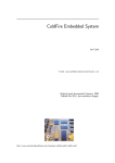
Owners Manual
INSTALLATION INSTRUCTIONS
1.Open Carton and Inspect Parts
Installation Parts included – refer installation diagram.
4.Connect Fittings to Cold Water Cistern Tap
(item 3 & 4)
• Apply plumbing tape to the existing ½” male
bsp water connection cistern tap fitting before
screwing on the connection fitting (3).
ITEM NO.
DESCRIPTION
1
K
-AU1000 Head Assembly
with mounting bracket
2
C
-AU1000 Quick Change Filter
Cartridge
3
C
onnection fitting to cold water
cistern tap
4
5
6
7
8
9
J
K
• Also apply plumbing tape to the ½” male bsp
connection on the outlet of the connection
fitting (3). Wrap tape in direction of the threads
to ensure a tight fit and avoid leaks.
• Re-Connect the ½” female bsp end of the
existing cold water hose to the ½” male bsp
end of the connection fitting.
• Take isolation valve (item 4) and wrap
plumbing tape around male bsp end. Screw
into connection fitting (item 3) ensuring that
the connection is sealed and tight.
Isolation valve
P
ressure Limiting Valve
Q
uick Connect ¼ ” Elbow fittings
Q
uick Connect Locking Clips
T
ubing ¼”
• Make sure that there is adequate space to
avoid crimping the water line plastic tubing.
M
ounting Screws
5. Install the Filter Tap
• Remove filter tap from carton and assemble
as shown below;
F
ilter Monitor Alarm
• Locate your filter tap position and drill a
12.7mm (½”) hole in the sink or benchtop to
accommodate the filter tap.
• Install the filter tap
C
hrome Filter Tap
2.ENSURE THAT THE COLD WATER IS
TURNED OFF
• Under the kitchen sink locate the cold
water isolation tap/valve.
• Turn the cold water off (check at main
kitchen tap that water is fully turned off
– if not, turn off at mains supply).
• Unscrew the braided flex hose from the
existing cold water isolation tap/valve.
• Clean the ½” male bsp water connection thread.
3.Under-sink Mounting Position for Head
Assembly
• Remove the Head Assembly (1) and Filter
Cartridge (2) from the carton.
• Insert cartridge into head assembly and
lock/twist until tight.
• Find a suitable location for the filter head
and cartridge on the back or side wall of the
under-sink kitchen cupboard – mark this
location. Don’t forget to allow at least 50 mm
underneath the bottom of the filter cartridge to
allow for filter replacement. Please ensure that
the location of the filter system is close to the
cold water connection and below where the
filter tap will be placed.
6. Inlet/Outlet Connection fittings
•Take the two quick connect ¼” elbow fittings
(item 6). Apply plumbing tape to threaded
male end and screw into inlet and outlet side
of filter head assembly (item 1).
7. Mount Filter Head under Sink
• Secure filter head, cartridge and mounting
bracket with screws provided in desired
location.
8.Connect Tubing to cold water inlet, Pressure
Limiting Valve (PLV) and inlet of Head
Assembly
• Remove plastic tubing from carton.
• T
he Pressure Limiting Valve (item 5) is
connected between the isolation valve (item 4)
and the Head Assembly (item 1).
• M
easure the desired length of tubing from the
isolation valve to the inlet of the PLV.
• C
ut tubing using Stanley knife or similar ensuring
the cut is square and clean.
Water Filter System
• R
emove tightening nut from isolation valve and
place over tubing then over isolation valve nipple
- secure with tightening nut.
• T
ake other end of tube and insert into inlet of
PLV - push in tightly then pull back to ensure
firm connection.
• W
hen pulling back plastic tubing, take a Quick
Connect Locking Clip (item 7) and secure it
behind the round collet to secure fitting - refer
installation diagram.
• M
easure length of the tube from the outlet of the
PLV to the inlet of the filter head assembly and
repeat the process.
• T
he Quick Connect Locking Clips should be
used on the two PLV connections, two head
connections and one tap adaptor connection.
9.Connect Tubing to outlet of Head Assembly
and to filter tap
• Measure length of tube from the outlet of the
head Assembly (right hand side) to the base
of the filter tap making sure that there are no
kinks in the tubing.
• Cut tubing to desired length using Stanley
knife or similar ensuring that the cut is square
and clean.
• Insert tube end into the Head Assembly “push
fit” connection on the outlet of the Head
assembly (right hand side). Push the tube in
tightly so that its firm – pull back on tube to
secure - insert locking clip.
• A
t other end insert tube into tap adapter. Push
tube in tightly so that it’s firm - pull back on
tube to secure - insert locking clip.
• Screw onto threaded base of the filter tap –
secure tightly.
NOTE – Flushing the filter cartridge is important
to remove air from the system and any loose
carbon. At first the water may appear cloudy
due to compressed trapped air in the filter and
hoses. However the cloudiness will disappear
over time and with use.
11.Installing the Filter Monitor Alarm (item 11)
The filter monitor alarm (item 11) is supplied
to assist you with knowing when it is time to
replace your filter cartridge. Regular annual
cartridge replacement ensures that your filter
system is maintained in accordance with the
manufacturers recommendations.
a) Remove double sided tape and plastic
wrapper from monitor.
b)On the back of the monitor - Pull the tab
back.
c) The LED and buzzer will cycle 3 times to
confirm the start.
d)It is programmed to flash and sound again in
12 months.
e) Remove the two adhesive tapes from the
back of the monitor and locate/mount in a
convenient location under your kitchen sink.
NOTES
1)This installation must comply with all
applicable state and local regulations
2)Do not use with water that is
microbiologically unsafe or of an unknown
quality without disinfection before or after
the system.
3)When storing filtered water in a
refrigeratorpleaseensurethecontainerhasan
air tight seal / lid.
10.Flush the Filter Cartridge
• Turn mains water supply back on at mini
cistern tap.
• Open cold water line at the isolation valve
• At this stage check for leaks and fix if
necessary
• Turn filter tap on and flush the filter cartridge
for at least 3 minutes. Collect water in
container and use for garden etc.
WARRANTY
Unit Description, Permitted Use and
Manufacturers Instructions for Use:
Unit Description:
K-AU1000
Product Specifications:
The unit must only be used for a potable water
source and with cold water (with a temperature
range between 5 and 38 degrees C). This unit
must be installed in accordance with state and
local laws.
Warranty
Water Filters Australia Pty Limited, Unit 1, 91-93
Old Pittwater Road, Brookvale, NSW Australia
2100 warrants to you, the first person who has
purchased and used the unit (“you”) that this unit
is free from defects due to faulty material and
workmanship in accordance with the conditions
set out in this document.
What this warranty covers:
This warranty covers defects due to faulty
material and workmanship of the unit supplied
to you:
• F
or a period of 1 year from the date of
purchase in respect of the entire unit,
excluding the Replaceable Elements
The Replaceable Elements are consumable
components and all parts of the unit which can
be replaced including but not limited to the filter
or water treatment cartridge if there is a defect in
the filter or cartridge. This does not include the
replacement of the filter or cartridge to extend
the life of the filter or cartridge. The life of the filter
cartridge is affected by water quality, usage and
water pressure.
The warranty only extends to the original
purchaser of the unit.
What this warranty does not cover:
This warranty does not cover the unit or a
Replaceable Element of the unit where:
• T
he defect, fault or failure is attributable, or
substantially attributable to misuse, abuse,
accident, misapplication, neglect, freezing,
oxidizing agents (including but not limited to
chlorine, ozone, chloramines and other related
components) or act of God;
• T
he unit has been in conditions which do
not conform to the recommended design
guidelines or has been operated in a manner
which is contrary to WFA’s printed instructions;
• T
he unit has not been installed in accordance
with WFA’s printed instructions and has not
been installed in compliance with all applicable
laws, regulations and industry standards;
• T
he unit has not been used in accordance with
the manufacturers instructions;
• T
he unit does not meet the conditions for use
described in the owners guide or performance
data sheet for this unit;
• Y
ou use accessories or components which do
not meet WFA’s specifications as set out in the
Installation and Operating Manual;
• T
he defect, fault or failure is due to normal
wear and tear;
• T
he defect, fault or failure has occurred where
the unit has been used reasonably or has
reached its serviceable life;
• T
he serial or model number label of the unit is
removed or defaced;
• T
he unit is serviced, modified, altered or
repaired by an unauthorized or unqualified
person;
• Y
ou have received incorrect advice from the
retailer or authorized dealer about the suitability
or capability of the unit;
The cost of freight for or relating to the repair or
replacement of the Replaceable Element or the
unit must be paid by you.
How to make a claim under this warranty:
To make a claim under this warranty you must
contact WFA within 21 days of the defect, fault or
failure occurring. WFA Warranty Contact number
is 1300 785 355 or alternatively contact us via
email [email protected] or by mail via
PO Box 636, Freshwater NSW 2096.
At the time of repair or replacement under your
warranty claim you must provide to WFA:
intend to use the unit or is appropriate for the
purpose for which you intend to use the unit.
• P
roof that you purchased the unit from an
authorized retailer or dealer within the warranty
time; and
WFA does not authorize others to assume any
obligation on its behalf even if you inform them of
the purpose for which you intend to use this unit.
• A
copy of a certificate which certifies that
the unit was installed in compliance with
our printed installation instructions and all
applicable laws, regulations and industry
standards.
Our goods come with guarantees that cannot
be excluded under the Australian Consumer
Law. You are entitled to a replacement or refund
for a major failure and for compensation for any
other reasonably foreseeable loss or damage.
You are also entitled to have the goods repaired
or replaced if the goods fail to be of acceptable
quality and the failure does not amount to a major
failure.
WFA will only pay for repair or replacement upon
receipt of proof of your purchase showing the
date of purchase.
Limitation of Liability of WFA under this
warranty:
Where a warranty exists or is implied by law,
WFA’s liability is limited (to the extent that it can
be limited) to repair or replacement of the faulty
Replaceable Element or the unit or an equivalent
unit. WFA may, in its discretion, choose whether
it shall repair or replace any unit or Replaceable
Element or WFA may choose to pay to you the
cost of replacing the Replaceable Element or the
unit or the cost of having the unit repaired.
To the extent permitted by law, WFA assumes no
liability whatsoever and disclaims all liability for
direct, indirect or consequential loss, or special,
general or other damage or expense caused by
or arising out of:
• A
ny failure to install or use the unit in
accordance with the Manufacturers
Instructions, the Installation and Operating
manual or WFA’s printed instructions; or
• T
he purpose for which you are purchasing the
unit.
You acknowledge that the quality of water supply
and your water usage rate and influent water
pressure may vary seasonally or over a period of
time. In addition to this water characteristics can
differ if the unit is relocated or the environment
changes.
You acknowledge that WFA does not know your
requirements and cannot and does not warrant
that the unit is fit for the purpose for which you
Warning
WFA does not recommend making alterations to
your existing plumbing to accommodate this filter
system. If you wish to modify existing plumbing
you must comply with AS 3500 and use a
licensed plumber.
Where internal water pressure exceeds 600 kPa
a Watermark approved Pressure Limiting Valve
must be installed prior to the filter system.
Warning
The contaminants or other substances removed
or reduced by this water treatment system are
not necessarily in your water supply. Do not use
with water that is microbiologically unsafe or of
an unknown quality without disinfection before or
after the system.
Important
This filter is designed to be used with mains/city
disinfected water supplies.
Caution
Safely isolate the water supply prior to installing
the filter system to avoid injury and property
damage.
Distributed by Water Filters Australia Pty Limited ABN: 78 089 574 489
Unit 1, 91-93 Old Pittwater Road, Brookvale NSW 2100
PO Box 636 Freshwater NSW 2096
Phone: +61 2 9905 6211
Fax: +61 2 9905 6255
Email: [email protected]
Web: www.waterfiltersaust.com.au
For all enquiries call the National Customer Service Centre on: 1300 785 355
• Check for compliance with state and local laws and regulations.
• T
he contaminants or other substances removed or reduced by this water filter
system are not necessarily in your water supply.
• D
o not use with water that is microbiologically unsafe or of an unknown quality
without adequate disinfection before or after the system.
• T
his drinking water system must be maintained in accordance to manufacturers
instructions, including replacement of filter cartridges.
• Installation instructions and standard warranty are enclosed herewith and included
with product when shipped.
Special Notes
Thank you for purchasing a Water Filters Australia under-sink
water filtration system. With your WFA AU1000 system, you get high quality
filtered water from a dedicated filtered water tap that’s clean, great tasting,
healthy and convenient for you and your family.
Owners Manual
Model: K-AU1000
Water Filter
System
Water Filter System
Installation Diagram
9
WFA Under-Sink Water Filtration System
Model: K-AU1000
Features
• In-built shut off valve in head enables filter change without turning off cold water.
4
• Carbon Block Filtration
• 12 months cartridge life (subject to water quality, usage and pressure)
• DIY Cartridge replacement – quick change bayonet style
5
3
8
1
6
• Chrome Designer Filter Tap
• Pressure limiting valve
COLD
HOT
• Filter alarm monitor
• Reduces Chlorine
• Reduces dirt, sediment particles and turbidity
• Reduces bad tastes and odours
• Compliant with NSF Standard 42.
7
10
2
Product Specifications
• Size Required: Height - 360mm
Width - 100mm
Depth - 100mm
11
FILTER ALARM
• Usage: For Cold Water Use Only
• Temperature Range: 5 – 38 C
• Min. – Max. Working Pressure: 25 – 100 psi
• Service Flow Rate: 3 Litres per minute
How to insert Quick
Connect Locking Clip
• Removes / Reduces :Chlorine, Turbidity, Bad tastes and odours, dirt and sediment particles
• Filter Change: 12 months or sooner if flow rate becomes inconveniently slow.
After pushing tube into
inlet valve, pull back on
tubing to ensure valve is
gripping tube, then insert
Locking Clip (item 7) into
space between the collet
lip and valve as shown.
• This filter unit does not remove fluoride