1
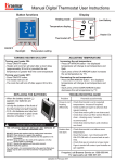
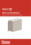
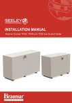
INSTALLATION MANUAL and
OWNER’S MANUAL
INTEGRATED COOLING SYSTEM
Y3500-Y3000
Y3510-Y3010
Y3520-Y3020
Heater Model
Indoor Coil
Outdoor Unit
TH5X23
TH5X23
TH5X32
TH4X20
TH4X25
TH4X30
TH3X20
TH3X25
TH3X30
Y3500
Y3510
Y3520
Y3500
Y3510
Y3520
Y3500
Y3510
Y3520
Y3000
Y3010
Y3020
Y3000
Y3010
Y3020
Y3000
Y3010
Y3020
Nominal Air
Flow
740 L/s
740 L/s
1060 L/s
700 L/s
820 L/s
1060 L/s
700 L/s
820 L/s
1060 L/s
Rated
Capacity
11.5 kW
13.0 kW
18.0 kW
10.8 kW
14.1 kW
18.0 kW
10.8 kW
14.1 kW
18.0 kW
Braemar Integrated Cooling
CONTENTS
Preface
3
Typical Installation
4
Indoor Cooling Coil Installation
5
Outdoor Unit Installation
10
Refrigerant Pipe-work
11
Electrical Wiring
12
Spectrolink Set Up
15
Zoning
17
Start up & Commissioning
20
Refrigerant Charge
21
Commissioning Sheet
22
Maintenance & Service
23
Before Calling for Service
24
Troubleshooting
25
Operation Tips
26
Technical Specification
27
Removal & Disposal Warning
28
Connection to Other Gas Ducted Heater Brands
28
Contact Details
29
NOTE: HOMEOWNER
Please keep this manual in a safe place along with a copy of your receipt and all relevant
certificates of compliance relating to the installation work performed.
The Braemar Integrated Cooling unit is a refrigerated cooling only,
split type air conditioning system, designed specifically for connection
to a Braemar “TH Extra Air” Series gas ducted heating unit, using
ONLY Braemar Spectrolink Comfort Control.
Read this manual before installation and operation.
Make sure that it is kept for later references.
Installation training is available from Seeley International for
qualified and licensed installers; please contact your local office for
training dates.
Effective from January 2011
V10 – Updated 2nd April 2011
Page 2
Braemar Integrated Cooling
PREFACE
Checking Received Product:
Upon receiving your unit, please inspect for damage. Claims for damage should be reported immediately with the
transportation company. Check the model number of the unit and ensure it matches your order. In the event an
incorrect unit is delivered, or, a damaged unit, it must be returned to the supplier and must NOT be installed. The
manufacturer assumes no responsibility for installation of incorrectly delivered units and/or damaged units.
Before Installation:
Read all instructions carefully prior to installation. Please ensure every step described in this manual is understood
and taken into account before starting installation.
Proper installation will help ensure trouble free operation.
Improper installation may result in problems such as noisy operation, compressor damage, improper operation or
dangerous conditions that could result in injury or property damage or void the warranty.
Over-current Protection:
Over-current protection which is less than the recommendation could result in unnecessary fuse failure and a
chargeable service call. The manufacturer bears no responsibility for damage caused to the equipment as a result of
deviation from the recommended rating.
Refrigerant tubing
Keep refrigerant tubing clean and dry prior to and during installation to avoid equipment damage. Tubing MUST
comply with all relevant local, state and national standards.
Homeowner
The user should retain this manual for future reference. To ensure the warranty is continued and valid, the
unit shall be required to be serviced as per section on “MAINTENANCE and SERVICE”.
Attention should be given to the air inlet side of the outdoor coil to ensure grass, leaf and other matter are not drawn
into or onto the Inlet side of the unit. Restriction to air flow across the coil will reduce the system capacity, result in
high operation pressures and excessive operating cost.
A return air filter MUST be installed at the return air grille. Air filters should be inspected and cleaned at least every
two weeks.
Low level return air grilles are recommended.
Your air conditioner is designed and built with reliable components to provide years of trouble free dependable
service. However, it does require regular maintenance either by yourself (end user) and/or a licensed technician to
keep your warranty on the unit valid.
IMPORTANT- THE AUSTRALIAN GREENHOUSE OFFICE HAS ISSUED VARIOUS
REGULATIONS ON THE USE AND DISPOSAL OF REFRIGERANTS IN THE UNIT. FAILURE
TO FOLLOW THESE REGULATIONS MAY HARM THE ENVIRONMENT AND COULD
LEAD TO THE IMPOSITION OF SUBSTANTIAL FINES.
ONLY QUALIFIED AND LICENSED TECHNICIANS SHOULD PERFORM WORK ON THIS
UNIT, FAILING WHICH THE WARRANTY ON THE UNIT WILL BE VOID.
Warning:
This appliance is not intended for use by persons (including children) with reduced physical, sensory or mental
capabilities, or lack of experience and knowledge, unless they have been given supervision or instruction
concerning use of the appliance by a person responsible for their safety.
Children should be supervised to ensure that they do not play with the appliance.
- The appliance shall be installed in accordance with national wiring regulations.
- Disconnecting devices must be incorporated in the fixed wiring in accordance with the wiring rules.
Effective from January 2011
V10 – Updated 2nd April 2011
Page 3
Braemar Integrated Cooling
INTEGRATED COOLING COIL
Effective from January 2011
V10 – Updated 2nd April 2011
Page 4
Braemar Integrated Cooling
Effective from January 2011
V10 – Updated 2nd April 2011
Page 5
Braemar Integrated Cooling
INDOOR COOLING COIL UNIT INSTALLATION
C
B
Return air connection
is NOT permitted on
the motor side of the
fan assembly.
A
Seeley supplied duct
transitions MUST be used!
MAKE SURE THE COOLING COIL IS INSTALLED WITH AIRFLOW IN THE DIRECTION
AS SHOWN ON THE DECAL ON THE UNIT.
Seeley recommends the use of a safe tray under the cooling coil, complete with a separate drain.
• The cooling coil can be mounted on a suitable base. Ensure that the base is level and that the drains are free
to be piped correctly with enough height to allow for condensate trap and fall to waste.
Alternative method – hanging from above;
• Measure and mark the position for the suspension bolts or rods. Be sure the position does not interfere
with anything and there is sufficient height to allow for adequate drainage from the unit.
Effective from January 2011
V10 – Updated 2nd April 2011
Page 6
Braemar Integrated Cooling
“TH” Extra Air heaters are designed for use with an Integrated Cooling refrigerated cooling systems.
• These models include an “X” in their model numbers, eg, TH3X20, TH4X30 and TH5X32. The following
points must be taken into account to ensure correct operation of both the refrigerated cooler and the heater.
• Ensure that the refrigerated cooling unit is sized correctly to suit the house and the heater.
• The cooling coil (evaporator) should be installed 1.5 to 2.5 m from the heater supply air outlet.
• To prevent excessive air flow restriction, the ducting between the heater and the cooling coil should be as
straight as possible. If bends are required, use the largest bend radius possible.
• The thermistor must be located after the cooling coil 3m along the duct from the heater outlet, and fitted
centrally in the top of the duct.
• A correctly-sized low level return air grille with a filter MUST be fitted when installing Integrated Cooling
refrigerated cooling – refer table ON PAGE 9 as a guide:
NOTE:
The “A/C” terminals on the BSC circuit board in the heater supply 24Vac control voltage to operate the cooling
system. The connection from the “TH” heater is direct to the Terminals marked “1 & 2” on the Integrated Cooling
outdoor terminal strip. Refer Page 12.
Ensure that “COOL 2” is selected during system set-up to enable the system to operate the refrigerated cooling
system - refer to “Commissioning” section in these instructions.
DUCT CONNECTIONS:
Effective from January 2011
V10 – Updated 2nd April 2011
Page 7
Braemar Integrated Cooling
INDOOR COIL
Effective from January 2011
V10 – Updated 2nd April 2011
Page 8
Braemar Integrated Cooling
INDOOR COOLING COIL UNIT INSTALLATION
Heater
Model
Indoor
Coil
Outdoor
Unit
Nominal
Air Flow
Rated
Capacity
TH5X23
TH5X23
TH5X32
TH4X20
TH4X25
TH4X30
TH3X20
TH3X25
TH3X30
Y3500
Y3510
Y3520
Y3500
Y3510
Y3520
Y3500
Y3510
Y3520
Y3000
Y3010
Y3020
Y3000
Y3010
Y3020
Y3000
Y3010
Y3020
740 L/s
740 L/s
1060 L/s
700 L/s
820 L/s
1060 L/s
700 L/s
820 L/s
1060 L/s
11.5 kW
13.0 kW
18.0 kW
10.8 kW
14.1 kW
18.0 kW
10.8 kW
14.1 kW
18.0 kW
Min Return
Air Filter
Size
0.36m²
0.36m²
0.48m²
0.36m²
0.40m²
0.48m²
0.36m²
0.40m²
0.48m²
Duct Connection Sizes
A
B
C
400
400
450
400
400
450
400
400
450
400
400
450
400
400
450
400
400
450
400
400
450
400
400
450
400
400
450
FLEXIBLE DUCTWORK CONNECTIONS
•
•
•
It is important that all ductwork be fitted securely and with airtight connection.
Use the supplied square to round transitions for proper and even air flow across the coil and through the
heater.
For flexible duct to transition, unit or outlets, provide a mechanical connection using strapping or banding in
addition to duct tape for air seal. Do not rely on tape only.
Important Notes:
1. Ensure 1.5m to 2.5m of straight duct between DGH and INTEGRATED COOLING.
2. Ensure DGH duct thermistor is located downstream of INTEGRATED COOLING and not more than
3m from the DGH.
3. Ensure that a minimum of 2 1/2 times the duct diameter of straight ductwork is installed, immediately
downstream of the indoor unit before any divergence or branch-take offs.
4. Fill and test drain before running the system.
IN CEILING INSTALLATION
When the indoor unit is installed in roof or ceiling space, an additional Safety Drain Tray (not supplied) must be
installed under the indoor unit.
- For servicing, a minimum clearance of 600 mm must be provided in front of the access panel side of the unit for
its entire length.
- Always install the "P" trap as close to the unit as possible. Fill the "P" trap with water during installation before
starting unit to prevent air movement through the drainpipe.
NOT ACCEPTABLE
WARRANTY VOID
DRAIN MUST BE
TRAPPED WITH A MIN.
50mm WATER SEAL
Effective from January 2011
V10 – Updated 2nd April 2011
Drain MUST have a
minimum 1:100 fall to waste.
Drain MUST comply with all
local, State and Prescribed
laws governing its
termination and installation.
Indoor Coil may be
suspended on hanging rods
or placed on a suitable
platform.
Page 9
Braemar Integrated Cooling
Location considerations should:
•
•
•
•
•
•
•
•
•
•
•
•
•
Most importantly, do not install the outdoor unit where there is a possibility it will cause a noise complaint from
your neighbours. Be mindful of the environment.
Allow sufficient clearances for maintenance around the unit. (See above)
Be well ventilated, so that the unit can draw and distribute sufficient air.
Be capable of bearing the weight of the outdoor unit whilst also isolating noise and vibration. See the technical
section of this booklet for weights and dimensions.
Wherever possible protect the unit from direct sunlight.
When installing by the seaside remember to make allowances to have the unit washed down to protect against
the salt spray.
Allow for drainage of rainwater.
Not discharge air towards the prevailing wind. This may stall the condenser fan.
Ensure air discharge and operating sound levels conform to local requirements.
Not be susceptible to dust or oil mist.
Ensure intake air temperature is no higher than ambient temperature. (Max. 45°C)
Adequate and reliable power supply.
Proximity to Indoor Coil – Minimum 3m Maximum 30m (Note: Capacity is based on 7.5m field installed pipe)
Effective from January 2011
V10 – Updated 2nd April 2011
Page 10
Braemar Integrated Cooling
OUTDOOR UNIT INSTALLATION
PIPE-WORK
Pipe-work must be installed in a manner which prevents drainage of liquid into the compressor, and ensures
adequate oil return. Pipes should be at least 3 m. in length, incorporating at least two direction changes. This will
reduce transmission between indoor and outdoor units.
Pipe-work to be installed according to the Current Code of Good Practice for refrigeration and Airconditioning
• Select pipe-work size from Table.
• Both interconnection lines must be insulted (minimum 10 mm thickness).
• Do not allow moisture, dust or other foreign particles to enter the pipe-work.
• Only use refrigeration grade copper tubing, suitable for R410a and to Australian Standards.
• Installed pipe-work must be pressure tested to a minimum of 300 kPa for at test 1 hour using dry nitrogen
• Pipe work must not be buried underneath the ground.
Vertical/Horizontal Pipe-work
Maximum vertical rise is 15m with all traps risers every 6 m.
Maximum Total length of pipe-work must not exceed 30m.
Brazing
If brazing of pipe-work is required, dry nitrogen must be used to purge the pipe-work during welding. When brazing
close to the flare nuts, a wet cloth must be used to protect the valves.
Flaring
All flares must be done with a quality flaring tool, suitable for R410A and refrigeration flares.
Orifice
Ensure the orifice connections are tight and leak free on the indoor cool before releasing the refrigerant gas charge.
Pipe-work
Select copper pipes for gas and liquid as information in specific table (see the pipe table below) For dust and
moisture protection, before assembly of the pipe and its insulation, both ends of the pipe must be covered, Avoid
pipe bending as much as possible, If it is necessary to bend, the bending radius must be more than 4 cm.
The field installed pipe work and indoor coil MUST be connected to a vacuum pump
and evacuated down to a vacuum pressure of 100 microns minimum.
Connection between indoor unit and outdoor unit.
Unscrew the flare nut for releasing pressure gas in the indoor unit. If there is no high pressure gas blowing out, it is
the signal of a leaking indoor unit, check and test for leaks, repair and/or replace as required.
Flare the pipe's end with flare tool, ensuring a good quality flare is achieved.
Tighten flare nuts onto gas pipe and liquid pipe at the indoor unit and outdoor unit, with two holding spanners.
Pressure the Indoor unit & pipe work again with dry nitrogen and check for any joint leaks. Repair as necessary but
ensure the system under repair is not under pressure prior to brazing.
With the indoor unit pressure again released, evacuate the pipe work and indoor coil to a vacuum pressure of
100 microns minimum.
Hold Vacuum for at least 15 minutes.
Disconnect the vacuum pump whilst retaining the system vacuum.
Open the liquid line value fully and then suction line valve and hold for 15 minutes.
Duct Connection
Capacity
Model Number
Pipe Sizes
Min, Pre-charge,
Sizes
(kW)
Indoor / Outdoor
Liquid / Vapour
Max Pipe Length
Cool
A
B
C
9.53 (⅜) / 19.05 (¾)
3 - 7.5 - 30
11.50
400
400
400
Y3500 / Y3000
12.70 (½) / 19.05 (¾)
3 - 7.5 - 30
14.20
400
400
400
Y3510 / Y3010
18.00
450
450
450
12.70 (½) / 19.05 (¾)
3 - 7.5 - 30
Y3520 / Y3020
Effective from January 2011
V10 – Updated 2nd April 2011
Page 11
Braemar Integrated Cooling
OUTDOOR UNIT INSTALLATION
MAINS & CONTROL WIRING
Licensed trades persons must carry out all the wiring work. Check SAA WIRING RULES for
PROTECTION sizing and cable sizes. Always refer to the relevant wiring standard for the electrical
installation.
Some local Supply authorities have restrictions on starting current of systems. Check Authority for
starting requirements for large single-phase compressor models.
Depending on model requirements 240-volt single phase, Neutral & Earth OR 415 volt 3 phase, Neutral &
Earth is required. All units are for 50 Hz operation.
Voltage at the unit, under load conditions, must be within the range of
Single phase
240V minus 10% or +5%
Three phase
415V minus 10% or +5%
24 volt Electrical Supply Connections
A control wire (24Volt) is required between the heater’s Integrated Cooling board and the Outdoor Unit.
A separate mains power feed is required for the Outdoor Unit.
24 volt supply is standard from the Braemar gas ducted heater “BSC” board
Connect 2 wire (1.5mm²) from “A/C 24 volt Refrig Output” to Terminals “1 & 2” on the Integrated
Outdoor unit wiring is to be done as shown in the electrical wiring diagram (Do not change the internal wiring)
24 Volt control wiring is required to be installed between the Outdoor Unit and the Heater (NOT SUPPLIED) in
accordance with the wiring instructions.
After fitting the wire, check that all the terminal screws are firmly tightened.
Effective from January 2011
V10 – Updated 2nd April 2011
Page 12
Braemar Integrated Cooling
ELECTRICAL WIRING
Effective from January 2011
V10 – Updated 2nd April 2011
Page 13
Braemar Integrated Cooling
ELECTRICAL WIRING
Warning:
The insulation of the fixed wiring may come into contact with hot surfaces, eg. Discharge pipe, the fixed wiring
insulation must be protected and/or separated properly from hot surface.
The minimum nominal cross-sectional area of supply cord shall be not less than:
MODEL
Y3500 / Y3000
Y3510 / Y3010
Y3520 / Y3020
Control cable
from heater
ELECTRICAL RATING
PHASE HERTZ POWER*
1
50
4.70kW
1
50
6.70kW
3
50
6.80 kW
1
50
VOLTS
220-240
220-240
380-415
24
FUSE
25 amp
40 amp
11 amp
Minimum cross-sectional area of
conductors (mm²)
4.0
6.0
1.5
1.5
(2 Core Multi Stranded Cable)
WARNING:
If incorrect rotation continues severe irreversible damage will result. This will void the warranty.
Some units are fitted with a phase rotation relay and will not start if the rotation is incorrect.
On three phase units correct compressor rotation must be checked. If the compressor is noisy and there is no suction
pressure this will indicate incorrect rotation. To change the direction of rotation, turn the power off and change any
two phases on the main terminal block.
The system must be started under the guidance of a qualified and accredited air-conditioning mechanic.
ELECTRICAL SHOCK CAN CAUSE PERSONAL INJURY OR DEATH
Before start up the electrical wiring must be checked for correct terminal locations, and that power is available on
each phase. On three phase units there must be 415 V
*Power shown is at the Maximum Test Conditions, refer below
Maximum Conditions *
Indoor Temperature
Cooling
o
32 C DB/23 C WB
Outdoor Temperature
43 C DB/-- C WB
Effective from January 2011
o
V10 – Updated 2nd April 2011
o
o
Page 14
Braemar Integrated Cooling
SPECTROLINK COMFORT CONTROL SET UP:
One hour time limit on settings adjustment
To help guard against inadvertent adjustment by the customer, setting the maximum fan speed, zones
installed, zone fan speeds and heater and cooler type must be done within the first hour of powering the
SCC thermostat. After this time the SCC must be disconnected, its capacitor discharged and re-connected.
The procedure on the following pages refers to commissioning the Spectrolink Comfort Control within the
1st hour of the first time power is applied to the system. However if you are commissioning the Integrated
Cooling more than 1 Hour after first applying power the following procedure is required.
Discharge SCC Capacitor;
1. Isolate the power to the heater
a. Remove SCC from wall bracket and unplug loom
2. Short the 2 terminals on the capacitor
a. Care needs to be taken
b. Use only a small device such as a paper clip or similar
c. Hold short for 30 seconds or until display is completely blank
3. Reconnect loom and replace SCC in wall bracket
4. Reapply power to the heater
Note: Time and day will need to be reset. All previous programming set by the
homeowner/installer will remain in the memory. (To change refer to Home Owners Manual).
CAPACITOR
CAPACITOR TERMINALS
APPLY SHORT ACROSS HERE
WARNING:
BE GENTLE – DO NOT APPLY
TOO MUCH PRESSURE
DO NOT BEND OR MOVE
CAPACITOR
Effective from January 2011
V10 – Updated 2nd April 2011
Page 15
Braemar Integrated Cooling
SPECTROLINK COMFORT CONTROL SET UP:
For 3, 4 & 5 Star Gas Ducted Heaters.
DEFAULT HEATER & COOLER TYPE:
SCC thermostats are set to the following default heater and cooler type:
• HEAT 3: TH series heater (or any other Braemar heater fitted with BSC control
system)
• COOL 1: Evaporative cooler (with CPMD control)
CHANGING THE DEFAULT TO SUIT INTEGRATED COOLING
•
•
•
•
With the SCC in OFF mode, press SET & AC MODE simultaneously
HEAT 3 – will appear first, DO NOT CHANGE, press SET to move to COOLING:
COOL 1 – will appear as this is the default setting
Use the UP/DOWN arrows to adjust the cooler type to COOL 2, press SET when satisfied
This can only be done within the first 15 minutes of powering the SCC. After this time:
• Disconnect SCC from the loom
• Discharge capacitor at back of SCC
• Re-connect to loom
CHANGING THE DEFAULT FAN SPEEDS:
Applicable to 4 & 5 Star Gas Ducted Heaters Only
The Table below shows the default fan speeds for each “Zone”
Operating Mode
HEAT 3
COOL 2
1 SCC
Multiple SCC
1 SCC
Multiple SCC
DEFAULT FAN SPEEDS
Zone Fan Speeds
Maximum
Fan speed Common
Zone 1
Zone 2
Zone 3
10
8
8
8
5
10
N/A
8
8
5
10
Heat + 2 Heat + 2 Heat + 2 Heat + 2
10
N/A
Heat + 2 Heat + 2 Heat + 2
Zone 4
5
5
Heat + 2
Heat + 2
The same procedure is used when either HEAT or COOL mode is selected. If the fan speed is set when HEAT is
selected, the default value for COOL will be the HEAT setting plus 2. Thus if “Zone 1” is configured with a fan
speed of “5” for HEAT, when COOL is selected, “Zone 1” fan speed will be “7” by default. This applies to all four
zones.
Therefore, as part of the commissioning procedure, “Zone” fan speeds must be set to reflect the number of outlets
available and the design air flow required, thus, supplying the correct amount of heated or cooled air to each Zone.
SETTING THE HEATER MAXIMUM FAN SPEED
With SCC in off state:
• Press and hold "SET" button, and while still holding SET button, press "FAN" button
• Room fan starts at speed 10
• SCC displays:
o Flashing “SET”
o Rotating fan symbol
o Flashing Fan Speed
• Use up/down arrows to adjust fan speed between 7, 8, 9 or 10 to desired air flow
• Press "SET" when satisfied to lock in selection
• SCC returns to off state
Effective from January 2011
V10 – Updated 2nd April 2011
Page 16
Braemar Integrated Cooling
REFRIGERATED COOLING ZONING
TH3 SERIES:
The TH3 Series Braemar Ducted Gas Heaters do not have the ability for zoning; a Spectrolink Comfort Control
must be used to operate the Integrated Cooling.
Therefore, any 3.7 star ducted heaters will have all outlets open for heating and all open for cooling. Unless the
zoning is controlled by an after-market zoning control system. If this is fitted to your 3.7 star system, please refer all
zoning issues back to your installer.
TH4 & TH5 SERIES: SPECTROLINK COMFORT CONTROL (SCC)
TH4 and TH5 model heaters can be installed and set-up to independently heat different areas within the home,
either from a single Spectrolink Comfort Control (SCC) or from up to four independent SCC's.
In each case zone dampers must be installed into selected duct runs to allow the air flow to a zone/s to be switched
“ON” or “OFF”.
1 SCC Thermostat: Includes a “Common Zone” with 1 to 4 Zones.
Each zone is controlled independently from a single SCC. The SCC must be located in a "common zone", ie, a zone
that cannot be turned off, and that includes the return air.
Multiple SCC thermostats: No “Common Zone” with up to 4 Zones.
Each zone is controlled independently from its own SCC - this allows zones to be set at different temperatures, and
to be controlled from within the zone. Each zone that has its own SCC thermostat must include a zone damper.
SETTING ZONES INSTALLED IN A SINGLE “SCC” INSTALATION
With SCC in off state:
• Press and hold "SET" button, and while still holding the SET button, press "ZONE 1" button
• SCC displays:
o Flashing “SET”
o Flashing “ZONE”
o Zone cross
•
•
Press zone buttons "ZONE 1/2/3/4" to enable required zones
SCC displays:
o Zone No as each zone button is pressed
o Zone cross
o Flashing SET
•
•
Press SET when all required zones are displayed to lock in selection
SCC returns to off state
Effective from January 2011
V10 – Updated 2nd April 2011
Page 17
Braemar Integrated Cooling
SETTING ZONES INSTALLED IN A MULTIPLE “SCC”
INSTALLATION
For TH4/5 models fitted with multiple SCC thermostats, the system automatically detects the number of SCC's
connected and enables those zones - manual setting of zones installed is not required. If the displayed zones and the
installed SCC's do not match it indicates that the system has not detected all SCC's (check looms and connections).
SETTING ZONE FAN SPEEDS
SINGLE “SCC” INSTALLATION
With SCC in OFF state: Mode: HEAT
•
•
•
•
Press and hold "FAN" button, and while still holding the FAN button, press "ZONE 1" button
Room fan starts at speed 8 (default for common zone)
Set fan speed for common zone:
o All zone dampers close
o SCC displays:
• ZONE and zone cross
• Flashing SET
• Rotating fan symbol
• Flashing fan speed (initial speed displayed is default speed)
o Use up/down arrows to adjust fan speed between 1/2/3/4/5/6/7/8/9/10 to desired air flow for
common zone
o Press "SET" when satisfied to lock in selection
Set fan speed for zone 1:
o Zone 1 damper open, all others closed
o SCC displays:
• ZONE and zone cross
• 1 (zone number)
• Flashing SET
• Rotating fan symbol
• Flashing fan speed (initial speed shown is default or previous set speed)
• Use up/down arrows to adjust fan speed to achieve desired air flow for the common + zone
1 – this cannot be less than the common zone fan speed
o Press "SET" when satisfied to lock in selection
o Go to next zone until all enabled zone are set
SCC returns to off state once the fan speed for the last zone is set.
Change Mode to COOL, repeat above procedure.
Effective from January 2011
V10 – Updated 2nd April 2011
Page 18
Braemar Integrated Cooling
MULTIPLE “SCC” INSTALLATION
NOTE:
For TG/TH Heaters prior to 31st December 2010, Zone 1 will default OPEN for COOL as it becomes the
COMMON ZONE.
For TH Extra Air Heaters manufactured after 1st January 2011, each zone operates individually, in both
Heating and Cooling Mode. There is no COMMON ZONE, thus the appliance has the ability to HEAT or COOL
any one zone.
Care must be taken to ensure the correct amount of air is set, thus, supplying each zone with sufficient cooling
capacity.
With SCC in off state: Mode HEAT
•
•
•
Press and hold "FAN" button, and while still holding the FAN button, press "ZONE 1" button
Room fan starts at speed 8
Set fan speed for zone 1:
o Zone 1 damper open, all others closed
o SCC displays:
• ZONE and zone cross
• 1 (zone number)
• Flashing SET
• Rotating fan symbol
• Flashing fan speed (initial speed displayed is default or previous set speed)
• Use up/down arrows to adjust fan speed between 1/2/3/4/5/6/7/8/9/10 to achieve desired air
flow for zone 1
• Press "SET" when satisfied to lock in selection
• Go to next zone, repeat above procedure, until all enabled zones are set
•
SCC returns to off state once the fan speed for the last zone is set.
If a fan speed greater than HEAT fan Speed + 2 are required, then you must change Mode to COOL, and
repeat above procedure.
One hour time limit on settings adjustment
To help guard against inadvertent adjustment by the customer, setting the maximum fan speed, zones installed, zone
fan speeds and heater and cooler type must be done within the first hour of powering the SCC thermostat. After this
time the SCC must be disconnected, its capacitor discharged and re-connected.
Effective from January 2011
V10 – Updated 2nd April 2011
Page 19
Braemar Integrated Cooling
START UP & COMMISSIONING
•
•
•
•
•
•
Ensure that a Return Air Filter is fitted prior to fan start up. (Filters are not supplied with the unit as
standard).
Ensure the Electrical has been connected and switch on at Isolator.
Switch the unit on in cooling mode with the thermostat set to minimum temperature set point.
Check suction and liquid pressure, check running current, check for noise and vibration, repair and/or
rectify as required.
o If all of the above are satisfactory, allow the system to run before starting to test the Super Heat.
If charging by weight, it is best to calculate the required additional weight, according to the chart below,
and add the refrigerant R410A after successfully evacuating and testing the field installed pipes. Add the
extra refrigerant prior to opening the service valves, check for leaks, and then open the service valves fully.
There is a Schroeder Valve under the service port cap.
Important Note:
All Braemar Integrated Systems are required to be commissioned and the data recorded on the
Commissioning Sheet included with these Installation Instructions provided with the unit. Commissioning
sheets require a signature from the customer. The cost associated with a customer warranty call will be
charged back to the original Dealer / Contractor if evidence of commissioning at the date of start-up is not
available
WARNING:
THE INDOOR UNIT IS SUPPLIED WITH A HOLDING CHARGE OF DRY NITROGEN.
THE OUTDOOR UNIT COMES WITH R410A CHARGE FOR LINES UP TO 7.5 m.
Condensing units are supplied with R410A sufficiently charged for matching evaporator and approximately of
interconnecting tubing, depending on models. However during installation many things may happen, for example
accidental release of gas. The recommended procedures stated below are used to determination refrigerant charge in
the system.
Effective from January 2011
V10 – Updated 2nd April 2011
Page 20
Braemar Integrated Cooling
DETERMINATION OF CORRECT REFRIGERANT CHARGE
2 METHODS OF ADDING REFRIGERANT FOR PIPE LENGTHS OVER 7.5m
1/
WEIGHING EXTRA REFRIGERANT
CHARGE BY LENGTH OF PIPE
The unit is shipped with a charge suitable for 3 to 7.5 meters of pipe. Extra refrigerant, (g/m), determined from the
table below, MUST be added for each meter that the field installed pipe extends beyond 7.5m.
Model
Y3000
Y3010
Y3020
Refrigerant Charge (g/m) over 7.5m
58
110
110
Note: Where the difference in elevation between the indoor unit and the outdoor unit is greater than 5 meters, install
an oil trap every 5 meters, in the vertical pipe section.
2/
SUPERHEAT METHOD
CHARGE BY SUPERHEAT METHOD (COOLING CYCLE)
1. With both base valves fully open, connect a set of service gauges to the base valves service port, being careful to
purge the lines.
2. Allow the system to operate at least 10 minutes or until the pressures stabilize.
3. Temporarily install a thermometer on the suction (large) line near the condensing unit base valve. Make sure that
there is good contact between the thermometer and the refrigerant line and wrap the thermometer and line with
insulating tape to ensure accurate readings.
4. Determine the systems superheat as follows:
a. Read the system suction pressure.
b. Using the Saturated Suction Pressure (R410A) Table 1, determine the system saturated suction
temperature.
c. Read the suction line temperature from the thermometer.
d. The system superheat = the suction line temperature - the saturated suction temperature
5. Adjust the charge as necessary by adding charge to lower the superheat or RECLAIMING the charge to raise the
superheat in accordance to the operating parameter of the unit as shown in Table 2.
CAUTION:
REMOVE THE SERVICE GAUGE SET FROM THE LINES CAREFULLY. ESCAPING LIQUID
REFRIGERANT CAN CAUSE BURNS.
Effective from January 2011
V10 – Updated 2nd April 2011
Page 21
Braemar Integrated Cooling
BRAEMAR INTEGRATED - COMMISSIONING SHEET
Please complete at time of commissioning on site
CUSTOMER:
Name
…………………………………….
Date
…………………………………..
Street
…………………………………….
Dealer
…………………………………..
Suburb
…………………………………….
Installer …………………………………..
State
…………………………………….
Post Code
…………………. Phone (H)…………………….(W)…………………………
Gas heater Model …………………………… Serial No.
…………………..
Indoor Coil Model
…………………………… Serial No.
…………………..
Outdoor Unit Model
…………………………… Serial No.
…………………..
Air On Indoor Coil 0C – DB 0C –
WB0 C
Air on Outdoor Coil 0C – DB
Air Off Indoor Coil 0C – DB 0C –
WB0 C
Air off Outdoor Coil 0C – DB
Airflow –l/s (Measured)
If not measured please estimate l/s
Suction on Temperature 0C measured at suction Port
Suction Pressure - kPa / psi
Discharge Pressure – kPa / psi
Discharge Temperature calculated at compressor
Liquid Line temperature 0c
Superheat Temperature 0k
Suction Temperature required 0c
(calculated)
Piping run in meters (one way)
Suction line insulated – yes
Refrigerant added if any - kg
Outdoor unit position in relation to indoor coil in metres – Above
Condensate drain tested for leaks and water flow – yes
Below
or Level
Full load amps
Customer
Signature………………………………………………………...Date……………………………..
Installer signature…………………………………………….. .Date…………………………….
Signature ………………………………………………………. Date…………………………
Customer System design notes:
Zone details- please provide room details
Cooling mode:
Heating mode:
Common zone
…………………………………..
…………………………………………
Zone one …………………………………..
…………………………………………
Zone two …………………………………..
…………………………………………
Zone three
…………………………………..
…………………………………………
Zone four…………………………………..
…………………………………………
Effective from January 2011
V10 – Updated 2nd April 2011
Page 22
Braemar Integrated Cooling
MAINTENANCE AND SERVICE
Maintenance
To ensure on your warranty validity, continuing high performance, and to minimize the possibility of premature
equipment failure, periodic maintenance must be performed on the air conditioning system;
The minimum maintenance requirements for this appliance are as follows:-
FORTNIGHTLY:
1. Clean or replace the return air filter/s.
2. The cleaner the filter the more energy efficient this appliance will be to operate.
SIX MONTHLY:
3. Inspect indoor coil, drain pan and condensate drain. Clean when necessary.
4. Inspect the heaters fan motor and wheel for cleanliness and alignment. Clean, and align the motor assembly
where applicable.
5. Inspect outdoor coil, clean where necessary.
6. Inspect outdoor fans and motors. Ensure that fan blades are clean and adequately balanced.
7. Inspect the unit cabinet and insulation for damage and corrosion. Repair where necessary. Check for
vibration and excessive noise. Correct where necessary.
8. Inspect refrigerant tubing for oil accumulations. If oil is detected, leak test refrigerant tubing.
9. Check refrigerant charge by measurement of superheat and sub cooling, where necessary, adjust charge.
10. Check the tightness of electrical connections.
Filter Cleaning Checklist: Place a in each box when filter is cleaned each fortnight.
Start Date:
/
/
Six Monthly Checklists:
Year
Date
3
Maintenance Item Numbers from above
4
5
6
7
8
9
10
Year 1
Year 2
Year 3
Year 4
Year 5
Effective from January 2011
V10 – Updated 2nd April 2011
Page 23
Braemar Integrated Cooling
Check Before Calling for Service
Before calling Service, please check the following:
1. If a new installation, please contact the installer to ensure the installation has been
completed and commissioned.
2. You MUST have a control as shown – Braemar SCC, if not, please refer back to
your installer.
3. Does the display show any information?
a. If Yes, go to Step 4.
b. If No, check power supply to Heater.
i. Repair power supply and set time and day.
ii. Follow procedure in “Home Owner’s Manual” on how to set up and
operate your system.
iii. After completing the above checks and any fault rectified as required
and your appliance continues not to operate, CALL 1300 650 644
4. Does the display show a “Snow Flake” symbol?
a. If Yes,
i. Is there air coming out of the outlets in your home?
ii. If No,
1. Ensure SCC is set to COOL and the set point is below the room temperature
2. Check and clean return air filter
3. Check and open outlets and/or zones
4. Check duct for disconnection or damage
5. After the above have been checked and repaired as required, Call 1300 650 644
b. If Yes, continue below:
i. Check Circuit Breaker and/or Isolator to Integrated Cooling unit. If electricity is available,
the unit may be timing out on the inbuilt safety timer. Wait 5 minutes and re-check.
ii. If fan is blowing on Outdoor unit, check large pipe’s temperature, this pipe should be cold
to touch.
1. If not cold, please have the installer check for refrigerant leaks before calling
Braemar Service on 1300 657 506
iii. Does the Integrated Cooling run for short periods of time?
1. If No, refer 4.a.ii above
2. If Yes,
a. Check to ensure enough outlets are open
b. Check and clean return air filter
c. The Braemar SCC has special safety features built in to protect your
Integrated Cooling system. It will switch off the Integrated Cooling output
signal when the supply air temperature drops below a pre-set minimum
value and will restart after the supply air temperature rises by a pre-set
value and the delay timer has elapsed.
d. Call the installer to check you have the required number of outlets open
e. Once the above have been checked and repaired as required,
Call 1300 657 506
Please NOTE:
It is important you recognise if the fault is with the Ducted Heater or if the fault is with the
Refrigerated Cooling System. For prompt, efficient service, please follow the above before
calling the appropriate number below.
For Refrigerated Cooling Issues
For Ducted Heater Issues
Effective from January 2011
V10 – Updated 2nd April 2011
1300 657 506
1300 650 644
Page 24
Braemar Integrated Cooling
Troubleshooting:
Problem
A. The air conditioner
does not run.
Probable cause
1. Power failure.
2. Fuse blown or circuit breaker open.
3. Voltage is too low.
4. Faulty contractors or relay.
5. Electrical connections loose.
6. Thermostat adjustment too low (in heating
mode) or too high (in cooling mode).
7. Faulty capacitor.
8. Incorrect wiring terminal loose.
9. Pressure switch tripped.
1. Motor winding cut or grounded.
2. Faulty capacitor.
Remedy
1. Wait for power to resume.
2. Replace the fuse or reset the breaker.
3. Find the cause and fix it.
4. Replace the faulty component.
5. Retighten the connection.
6. Check thermostat setting.
7. Find the cause then replace capacitor.
8. Check and retighten.
9. Find the cause before reset.
C. There is
insufficient cooling.
1. There is a gas leak.
2. Liquid and gas line insulated together.
3. The room was probably very hot when you
started the system.
D. The compressor
runs continuously.
1. Thermostat adjustment too high (in heating
mode) or too low (in cooling mode).
2. Faulty fan.
3. Refrigerant charge too low, leak.
4. Air or incondensable in refrigerant circuit.
E. The compressor
starts but shuts down
quickly.
1. Too much or too little refrigerant.
2. Faulty compressor.
3. Air or incondensable in refrigerant circuit.
4. Blocked expansion device.
F. Clicking sound is
heard from the air
conditioner.
In heating or cooling operation any plastic
parts may expand or shrink due to a sudden
temperature change in this event, a clicking
sound may occur.
1. Remove charge, repair, evacuate and
recharge.
2. Insulate them separately.
3. Wait while unit has enough time to
cool the room.
1. Remove charge, repair, evacuate and
recharge.
2. Insulate them separately.
3. Wait while unit has enough time to
cool the room.
2. Find the cause then replace capacitor.
1. Remove charge, evacuate and
recharge.
2. Determine the cause and replace
compressor.
3. Remove charge, evacuate and
recharge.
4. Replace it.
This is normal.
B. The outdoor fan
runs but the
compressor will not
start.
Effective from January 2011
V10 – Updated 2nd April 2011
1. Check the wiring and the compressor
winding resistance.
2. Find the cause then replace capacitor.
Page 25
Braemar Integrated Cooling
Operation Tips
The following events may occur during normal operation.
1. Protection of the air conditioner.
Compressor protection
• The compressor cannot restart for 3 minutes after it stops.
• The supply air drops below a pre-determined set point; this prevents the indoor coil from freezing.
2. A white mist coming out from the indoor unit.
• A white mist may generate due to a large temperature difference between air inlet and air outlet on COOL
mode in an indoor environment that has a high relative humidity.
.
3. Low noise of the air conditioner.
• You may hear a low hissing sound when the compressor is running or has just stopped running.
This sound is the sound of the refrigerant flowing or coming to a stop.
• You can also hear a low “squeak” sound when the compressor is running or has just stopped running.
This is caused by heat expansion and cold contraction of the plastic parts in the unit when the temperature
is changing.
4. Dust is blown out from the indoor unit.
This is a normal condition when the air conditioner has not been used for a long time or during first use of the
unit.
5. A peculiar smell comes out from the indoor unit.
This is caused by the indoor unit giving off smells permeated from building material, from furniture, smoke, or
from the duct work.
6. The air conditioner turns to FAN only mode from COOL mode.
When indoor temperature reaches the temperature setting on air conditioner, the compressor will stop
automatically, and the air conditioner turns to FAN only mode. The compressor will start again when the indoor
temperature rises above the set point.
Effective from January 2011
V10 – Updated 2nd April 2011
Page 26
Braemar Integrated Cooling
TECHNICAL SPECIFICATION:
Braemar Part
Power Supply
Cooling Capacity
Rating*
Maximum current **
Fuse
Cabling (minimum)
Starting current
Soft starter
Evaporator coil
Goes with
Indoor dimension
Indoor weight
Outdoor coil
Compressor
Outdoor fan motor
Outdoor noise level
Outdoor dimension
Outdoor weight
Refrigerant
Piping Connection
Capacity
Power Consumption
EER
Number of row
Fin spacing
Fin material
Tube outside diameter
Tube material
Coil face area
Air Flow Rate (rating)*
HEATER - TH5X23
HEATER - TH5X32
HEATER - TH4X20
HEATER - TH4X25
HEATER - TH4X30
HEATER - TH3X20
HEATER - TH3X25
HEATER - TH3X30
Unit (H x W x D)
Net
Gross
Number of row
Fin spacing
Fin material
Tube outside diameter
Tube material
Coil face area
Type
Input
Rated current(RLA)
Locked rotor Amp(LRA)
Thermal protector
Capacitor
Refrigerant oil
Power Input
Running Current
Capacitor
Speed
Unit (W x H x D)
Net
Gross
Type
Charge
Liq / Gas / Drain
Max. refrig pipe length
Max. difference in level
Qty’ per 20/40/40HQ
mm
Y3000/Y3500
220-240/1/50
11.5
3.6
3.19
25
25
4
32
Y
3
1.80
mm
Ø9.50
OD/ID
V/Ph/Hz
kW
kW
W/W
A
A
2
mm
A
2
m
l/sec.
l/sec
l/sec
l/sec
l/sec
l/sec
l/sec
l/sec
l/sec
mm
Kg
Kg
mm
mm
m
2
W
A
A
mF
ml
W
A
µF
rpm
dB(A)
mm
Kg
Kg
g
mm
m
m
Set
0.20
733
755
Y3010/Y3510
220-240/1/50
14.2
4.8
2.96
34
40
6
44
Y
3
1.80
Un-hydrophilic aluminium
Ø9.50
Inner-grooved copper tube
0.20
813
755
Y3020/Y3520
380-415/3/50
18.0
5.6
3.21
11
11
1.5
45
N
3
1.80
Ø9.50
0.24
1052
1070
695
810
1050
695
810
1050
545x635x638
645x635x638
30
40
38
47.5
2
2
1.2
1.2
Un-hydrophilic aluminium
Ø7
Ø7
Ø7
Inner-grooved copper tube
0.73
1.18
1.34
Rotary
Scroll
Scroll
3210
4700
5130
16.1
27.3
12.5
88
153
68
Internal
Internal
Internal
60
50
1300
1656
1700
225
166 x 2
225 x 2
1.1
0.92 x 2
1.1 x 2
7.5
5
7.5
900
900
900
68
70
71
1012x815x412
1012x1275x412
1012x1442x412
85
110
115
91
122
125
R410-A
R410-A
R410-A
3300
4000
4200
Ø9.5 / Ø19 / ID.24
Ø12.7 / Ø19 / ID.24
Ø12.7 / Ø19 / ID.24
30
30
30
15
15
15
30/60/90
23/45/65
23/45/45
545x635x638
30
38
2
1.2
Remark: The above design and specification are subject to change without prior notice for product improvement.
Maximum Conditions
Rating Conditions *
Cooling
Cooling
**
o
o
o
o
Indoor Temperature
26 C DB/19 C WB
Indoor Temperature
32 C DB/23 C WB
o
o
o
o
Outdoor Temperature
35 C DB/24 C WB
Outdoor Temperature
43 C DB/-- C WB
Effective from January 2011
V10 – Updated 2nd April 2011
Page 27
Braemar Integrated Cooling
REMOVAL AND DISPOSAL
This product contains refrigerant under pressure, rotating parts and electrical connections which may be a
danger and cause injury!
All work must only be carried out by competent persons using suitable protective clothing and safety
precautions.
1. Isolate all sources of electrical supply to the unit including any control system supplies switched by the unit.
Ensure that all points of electrical and gas isolation is secured in the OFF position. The supply cables and
gas pipe-work may then be disconnected and removed. For points of connection refer to unit installation
instructions.
2. Remove all refrigerant from each system of the unit into a suitable container using a refrigerant reclaim or
recovery unit. This refrigerant may then be reused, if appropriate or returned to the manufacturer for
disposal. Under no circumstances should refrigerant be vented to atmosphere. Where appropriate, drain
the refrigerant oil from each system into a suitable container and dispose of according to local laws and
regulations governing disposal of oily wastes.
3. Packaged unit can generally be removed in one piece after disconnection as above. Any fixing down bolts
should be removed and then unit lifted from position using the points provided and equipment of adequate
lifting capacity. Reference MUST be made to the unit installation instructions for unit weight and correct
methods of lifting. Note that any residual or spilt refrigerant oil should be mopped up and disposed of as
described above.
4. After removal from position the unit parts may be disposed of according to local laws and regulations
CONNECTION TO OTHER GAS DUCTED HEATERS
Although we do not recommend it, you can connect the Braemar Integrated Cooling Unit to the gas ducted heaters
of other manufacturers. You will need to ensure that the gas ducted heater has the appropriate capability and
performance, and meets the specifications, that are required for safe and satisfactory operation of the Integrated
Cooling Unit. You will also need to ensure that the controller selected in place of the Braemar Spectrolink Comfort
Control is suitable to operate the Integrated Cooling Unit, and is correctly programmed. Proper installation and
commissioning is essential. Failure to comply with all of these requirements may result in the Integrated Cooling
Unit not performing adequately or at all, and void the warranty.
NOTE:
For complete warranty terms and conditions, refer to separate Warranty Card and/or www.braemar.net.au
Warranty conditions are subject to property access and industry Safety Standards. Seeley International strives for
continuous product improvements, therefore specifications are subject to change without notice. Unit colour may
vary slightly from that depicted in this booklet.
Installation and commissioning of this system to the manufacturer’s specification, compliance with industry
standards, and local, state and national regulatory codes are the responsibility of the installer.
Information in this booklet was true and correct at the time of publishing. E & OE.
Effective from January 2011
V10 – Updated 2nd April 2011
Page 28
Braemar Integrated Cooling
Warranty Service
For Refrigerated Cooling Issues
For Ducted Heater Issues
1300 657 506
1300 650 644
Prior to calling the service number please, read the trouble shooting section, “Check Before Calling for
Service” on page 22. When calling Warranty Service number, please ensure you have your model and
serial number available, along with date of purchase and if possible a description of the problem.
Technical support
1300 650 399
Technical Support is for Installers and Dealers ONLY.
Prior to calling Technical support please ensure you have the appliance model and serial number and any
relevant fault information.
Sales order office
1300 650 141
[email protected]
Head Office
Seeley International Pty Ltd
ACN 054 687 035 ABN 23 054 687 035
Sales Tax No. 8 671 721
112 O'Sullivan Beach Road
Lonsdale
South Australia 5160
Australia
PO Box 164
Lonsdale
South Australia 5160 Australia
Effective from January 2011
V10 – Updated 2nd April 2011
Page 29