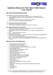
1
OPERATORS MANUAL
&
WARRANTY FORM
Gavhall Pty Ltd, trading as KANGA FARM EQUIPMENT, would like to thank you for choosing one of our
implements. Kanga Farm Equipment has manufactured three point linkage implements to handle the harsh
Australian Conditions, since 1982.
All new Kanga Farm Equipment Implements are backed with a 12 month comprehensive warranty, against
faulty workmanship and/or materials, under normal working conditions and service, as outline in this
manual. Your warranty maybe considered void if any damaged to the implement is caused by operator
abuse, neglect, or if any unauthorized modifications have been made.
Kanga Farm Equipment and its Distributors/Dealers are not responsible for any transportation cost
incurred in the repair or replacement of parts in either a successful or non-successful warranty claim. All
implements must be returned to the manufacture for warranty assessment.
This warranty does not exclude any conditions implied by the Trade Practices Act 1974, or any other
relevant legislation.
The information contained in this manual was current at the time of printing and has been compiled
especially to assist you with the Implement that you have purchased. It is of the utmost importance that you
read this manual and understand the context completely before attempting to operate the implement. Please
be aware that in an effort to bring you better products we are always implementing continuous
improvements that may change the designs and specifications of the Implement. In doing this, Kanga Farm
Equipment together with its Dealers and Distributors are under no obligation to implement these changes,
free of charge, on any previously delivered Implement
Kanga - Other Products Manual.docx
16 Cahill Street, Dandenong, Victoria, Australia, 3175
Tel: (03) 9706 5166
(PROP. GAVHALL PTY LTD)
ACN 006 050 657
ABN 59 918 752 500
Fax: (03) 9706 5050
TO THE DEALER
Assembly and proper installation of this product is the responsibility of the KANGA FARM EQUIPMENT dealer. The
dealer must complete all items on the Warranty Registration & Installation Form included in this manual before
releasing the implement to the new owner.
Both dealer and customer must sign the registration, which certifies that all Dealer Checklist items have been completed.
The dealer must return a copy of the Warranty Registration & Installation Form to Kanga Farm Equipment. Reminders
about Warranty Registration that have not been returned will be sent out to demonstrate that reasonable attempts have
been made to ensure dealers complete risk assessment and pre-delivery obligations.
TO THE OWNER
Read this manual before operating your KANGA FARM EQUIPMENT implement. The information presented will
prepare you to do a much better and safer job. Keep this manual handy as a reference. Ensure all operators read this
manual carefully and become acquainted with all the adjustments and operating procedures before attempting to
operate. Keep a record that the operator has read and understands the correct operating procedures as outline in this
manual.
The implement you have purchased has been carefully engineered and manufactured to provide dependable and
satisfactory use. Like all mechanical products, it will require routine cleaning, upkeep and maintenance. Lubricate the
implement as specified. Observe all safety information in this manual and safety decals on the implement.
Throughout this manual the term IMPORTANT is used to indicate that a failure to observe can cause damage to the
equipment. The terms CAUTION, WARNING and DANGER are used in conjunction with the Safety-Alert Symbol
(triangle with an exclamation mark) to indicate the degree of risk to your personal safety.
This Safety-Alert Symbol indicates a hazard and means ATTENTION! BE CAREFUL!
YOUR SAFETY IS INVOLVED!
DANGER indicates an imminently hazardous situation, which if not avoided, will result
in death or serious injury.
WARNING indicates a potentially hazardous situation, which if not avoided, could
result in death or serious injury.
CAUTION indicates a potentially hazardous situation, which if not avoided, may result
in minor or moderate injury. It may also be used to alert against unsafe practices.
GENERAL INFORMATION
The purpose of this manual is to assist you in operating and maintaining your KANGA implement. Read it carefully. It
provides information and instructions that will help you achieve years of dependable performance. These instructions
have been compiled from extensive field experience and engineering data. Some information may be general in nature
due to the unknown and varying operating conditions. However, through experience and these instructions, you should
be able to develop procedures suitable to your particular situation.
The illustrations and data used in this manual were current at the time of printing, but in an effort to bring you better
products we are always implementing continuous improvements that may vary your implement slightly in detail. We
reserve the right to redesign and change the machine as may be necessary without notice.
Some illustrations in this manual show the Digger with Safety Shields removed to provide a better view.
The Slasher should never be operated with any safety shielding removed.
Throughout this manual, references are made to right and left direction. These are determined by standing behind the
equipment facing the direction of forward travel. Blade rotation is as if viewed from the top.
2
Post Hole Diggers
Mini Range
M Range
H Range
XH Range (Hydraulic)
5
SPECIFICATIONS
MINI RANGE
3 – Point Linkage … … … … … … … … … … … … … …
Boom Material … … … … … … … … … … … … … …
Boom Material Measurements … … … … … … … … …
A Frame Material … … … … … … … … … … … … … …
Type of Tower
……………………………………
Gearbox … … … … … … … … … … … … … … … … …
Tractor PTO Speed
………………………………
Power Take Off Shaft (PTO)
………………………
Clutch Size and Type … … … … … … … … … … … …
# of Clutch Linings
………………………………
Weight (less auger)
………………………………
Max. Auger Size
………………………………
Category 1
Rolled Hollow Section (RHS)
80 x 80 x 4
65 x 12 Flat
Double Clevis Reinforced
35hp♦ (2.92:1 ratio)
Idle (540 rpm)
Series 2 (1500mm)
6” Slip Clutch
2
92kg
12” (305mm)
M RANGE
3 – Point Linkage … … … … … … … … … … … … … …
Boom Material … … … … … … … … … … … … … …
Boom Material Measurements … … … … … … … … …
A Frame Material … … … … … … … … … … … … … …
Type of Tower
……………………………………
Gearbox … … … … … … … … … … … … … … … … …
Tractor PTO Speed
………………………………
Power Take Off Shaft (PTO)
………………………
Clutch Size and Type … … … … … … … … … … … …
# Of Clutch Linings … … … … … … … … … … … …
Weight (less auger)
………………………………
Max. Auger Size
………………………………
Category 1
Rolled Hollow Section (RHS)
100 x 100 x 6
65 x 12 Flat
Double Clevis Reinforced
50hp♣ (3.18:1 ratio)
Idle (540 rpm)
Series 4 (1500mm)
6” Slip Clutch
2
133.6kg
24” (610mm)
H RANGE
3 – Point Linkage … … … … … … … … … … … … … …
Boom Material … … … … … … … … … … … … … …
Boom Material Measurements … … … … … … … … …
A Frame Material … … … … … … … … … … … … … …
Type of Tower
……………………………………
Gearbox … … … … … … … … … … … … … … … … …
Tractor PTO Speed
………………………………
Power Take Off Shaft (PTO)
………………………
Clutch Size and Type … … … … … … … … … … … …
# Of Clutch Linings … … … … … … … … … … … …
Weight (less auger)
………………………………
Max. Auger Size
………………………………
♦
Specifications for this Gearbox can be found on page 23 of this Operators Manual.
♣
Specifications for this Gearbox can be found on page 24 of this Operators Manual.
† Specifications for this Gearbox can be found on page 24 of this Operators Manual.
6
Category 1
Rolled Hollow Section (RHS)
100 x 100 x 6
65 x 12 Flat
Double Clevis Reinforced
75hp† (4:1 ratio)
Idle (540 rpm)
Series 4 (1500mm)
8” Slip Clutch
2
159.2kg
24” (610mm)
XH RANGE
3 – Point Linkage … … … … … … … … … … … … … …
Material
…………………………………………
Construction
……………………………………
A Frame Material … … … … … … … … … … … … … …
Tractor PTO Speed
………………………………
Hydraulic
………………………………………
Gearbox
………………………………………
PTO Shaft
………………………………………
Clutch … … … … … … … … … … … … … … … … …
Size of Clutch
……………………………………
# of Clutch linings
Max. Auger Size
………………………………
………………………………
Category 1 or 2
Rolled Hollow Section (RHS)
Heavy Duty Dual Rail with shear bolts
Rolled Hollow Section (RHS)
Idle (540 rpm)
2.5” Hydraulic Ram & hoses
50hp♣ (3.18:1 Reduction)
75hp† (4:1 Reduction)
50hp Gearbox - Series 4
75hp Gearbox - Series 6
Friction Slip Clutch
50hp Gearbox - 150mm (6”)
75hp Gearbox - 200mm (8”)
2
24” (610mm)
AUGERS
Length
……………………………………
Flighting Thickness … … … … … … … … … … …
Pilot (tip)
……………………………………
Tooth … … … … … … … … … … … … … … …
Sizes Available
…………………………………
1220mm (48”)
5mm
Heat Treated Cast Steel, replaceable
Nickel Alloy Steel hardened, replaceable
(4”) 100mm (13.5kg)
(6”) 150mm (14.5kg)
(9”) 228mm (19.5kg)
(12”) 305mm (24.5kg)
(15”) 380mm (27.2kg)
(18”) 457mm (34.5kg)
(24”) 610mm (60.5kg)
NT - Mini Range Post Hole Digger are limited an a maximum auger size of 305mm (12”). Augers larger than 12”
(305mm) should not be attached to a Mini Range Post Hole Digger as they may cause the 35hp gearbox to fail. In the
circumstance where a larger auger has been attached to a Mini Range Post Hole Digger and a failure occurs, it is likely
that the gearbox will not be covered by warranty.
♣
Specifications for this Gearbox can be found on page 24 of this Operators Manual.
† Specifications for this Gearbox can be found on page 24 of this Operators Manual.
7
SAFETY RULES & ACCCIDENT PREVENTION
ATTENTION! BE CAREFUL! YOUR SAFETY IS INVOLVED!
Safety is a primary concern in the design and manufacture of our products. Unfortunately, our efforts to provide safe
equipment can be wiped out by a single careless act of an operator.
In addition to the design and configuration of equipment, hazard control and accident prevention are dependent upon the
awareness, concern, prudence and proper training of personnel involved in the operation, transport, maintenance and
storage of equipment.
It has been said, “The best safety device is an informed careful operator.” We ask you to be that kind of operator.
•
•
•
•
•
•
•
•
•
•
•
•
•
•
•
•
•
•
•
•
Safety instructions are important! Read all attachments and unit manuals; follow all safety rules and safety decal
information. Failure to follow instructions can result in serious injury or death.
If you do not understand any part of this manual and need assistance the Department of Agriculture,
Occupational Health & Safety Offices, any Agricultural School or college and your local dealer should be able to
direct you on where you can received appropriate training. No operator however experienced in farm machinery
operation they maybe, should attempt to use any piece of machinery that they have not been competently trained
to use.
Keep hands and body away from pressurized lines. Use paper or cardboard, not hands or other body parts to
check for leaks. Wear safety goggles. Hydraulic fluid (oil) under pressure can easily penetrate the skin and will
cause serious injury or death.
Make sure that all operating and service personnel know that if hydraulic fluid (oil) penetrates the skin, it must be
surgically removed as soon as possible by a doctor familiar with this form of injury or gangrene, serious injury or
death will result. CONTACT A PHYSICAN IMMEDIATELY IF FLUID ENTERS SKIN OR EYES. DO NOT
DELAY.
Know your controls and how to stop quickly in an emergency.
Operators must be instructed in and be capable of the safe operation of the equipment and all controls. Do not
allow anyone to operate this equipment without proper instruction.
Do not allow children or untrained persons to operate equipment.
Check that all hardware is tight and properly installed.
Always wear relatively tight fitted clothing to avoid entanglement in moving parts. Wear heavy-duty, rough-soled
boots and protective equipment for eyes, hair, hands, hearing and head.
Ensure implement is properly attached, adjusted and in a good condition so that it can be operate safely.
Make sure all spring activated locking pins or collars on the Power Take Off (PTO) Shaft move freely, are well
greased and are firmly seated in the tractor PTO splined angular groove.
Before commencing operation, check all equipment driveline guards for damage and make sure they rotate freely.
Replace any damaged guards or guards that do not rotate freely on drivelines.
Tractors MUST be fitted with Roll Over Protection Structure (ROBS) or ROBS Cap. It is also advisable that
your tractor be fitted with a seatbelt, where fitted it must be worn at all times. Falling from your tractor can result
in death from being run over or crushed. If your tractor is fitted with a folding ROBS, keep it in the “locked up”
position at all times.
Inspect chains, shackles, deflectors and any wear parts for damage. Replace if damaged.
Remove any debris that has accumulated on the implement, tractor or engine to avoid fire hazard.
Ensure all safety decals are installed. Replace if damaged.
Ensure shields and guards are properly installed and in good working condition. Replace if damaged.
A minimum 20% of tractor and equipment weight must be on the tractor’s front wheels with implement in the
transport position. Without this weight, tractor could tip over causing personal injury or death. The weight
maybe attained with a loader, front wheel weights, and ballast in the tyres or front tractor weights. When
attaining the minimum 20% weight on the front wheels, you must not exceed the ROPS max ballasted mass
certificate. Weight the tractor and implement. Do not estimate.
Inspect operating area, remove where possible any stones or foreign objects that may cause injury or damage. It
is very important to always watch for foreign objects in the area you are operating and avoid any that could cause
injury or damage.
When working in populated areas always place signs in the area to alert people or vehicles that may pass.
Operation must be stopped when anyone comes within 50 meters.
8
•
•
•
•
•
•
•
•
•
•
•
•
•
•
•
•
•
•
•
•
•
•
•
•
•
•
•
•
•
•
•
•
•
•
Keep all people and animals away from the implement during start up, operating and when stopping.
Never place hands or any part of your body against auger, gearbox, PTO or boom to aim the auger.
Shift tractor transmission into park or neutral and set park brake before engaging PTO and digging.
Keep digger under control by running PTO at slowest speed possible. No faster than half throttle in 540-rpm
range. Always ensure the correct setting of 540 rpm is selected on your tractor before start up.
Use extreme care when working close to fences, ditches, hillsides or other obstacles.
Do not operate or transport on steep slopes. If in doubt set rear axles wider for moderate slopes.
When digging on unstable or hilly terrain, place digger uphill from the tractor.
When dislodging a stuck auger, disengage PTO, stop engine, remove key, disconnect PTO and turn auger in
reverse with a wrench. Remove and store wrench and reconnect PTO before starting engine.
Never leave a tractor and implement running unattended.
Do not operate the implement or tractor while under the influence of drugs or alcohol.
Operate only in daylight or good artificial light.
Keep hands, feet, hair, and clothing away from moving parts while engine is running.
For transportation on public roads the operator must ensure that the tractor and implement complies with
current State and Federal laws and must strictly adhere to all road traffic regulations in force in his/her particular
state.
Always operate equipment from the seat of the tractor with the seat belt securely fastened especially when
operating controls or starting engine. Place transmission in neutral, engage break and ensure all other controls
are disengaged before starting tractor engine.
Do not operate tractor PTO during transport or when implement is raised more than 150mm above the ground.
Look down and to the rear and make sure area is clear and safe before traveling in reverse.
Do not stop, start or change directions suddenly when traveling on slopes.
Use extreme care and reduce ground speed when traveling on slopes and rough terrain.
Stop implement, then tractor, immediately upon striking an obstruction. Turn off engine, remove key, inspect and
repair any damage before resuming operations. Always block implement when inspecting.
Before commencing any adjustment, maintenance, or cleaning. Always disengage the Power Take Off (PTO)
Shaft, switch off the tractor engine, remove key and wait until all moving parts have come to a complete stop, then
ensure the machine is on the ground or on a robust secure support.
Before dismounting tractor or performing any service or maintenance, disengage power to implement, lower the
3-point linkage and any other raised components (i.e. loader bucket) to the ground. Operate valve levers to release
any hydraulic pressure, stop engine, set parking brake, remove key and unfasten seat belt.
Disconnect driveline from the tractor PTO before performing any service work.
Never place any part of the body underneath the implement or between moveable parts even when engine has
been turned off. Hydraulic systems can “creep” (i.e. slowly lower). They may fail or movement of the control
levers can cause the implement to drop or rotate unexpectedly causing severe injury or death. Follow Operator’s
Manual instructions for working on your implement or have servicing carried out by a qualified dealer.
During routine checks and/or repairs ensure that no one can switch on the tractor or Implement accidentally.
Keep the key to the tractor in your pocket.
For your own safety and that of others and to avoid forfeiting your warranty, use only original spare parts.
Do not modify/alter or permit anyone else to modify/alter the implement or any of its components.
Ensure implement is properly attached, adjusted and in good operating condition.
Frequently check teeth & pilot. They should be sharp, free of nicks and cracks and securely fastened.
Do not handle teeth & pilot with bare hands. Careless or improper handling may result in serious injury.
Your dealer can supply you with genuine replacement parts.
Firmly tighten all nuts, bolts, screws and shackles before operating. If worn or damaged then replace
immediately.
Block implements securely for storage.
Keep children and bystanders away from storage area.
Kanga Farm Equipment accepts no responsibility or liability for any losses, injuries or damages that may result
from failing to observe these safety rules and the safety decals on the implement.
9
SAFETY RULES & ACCCIDENT PREVENTION
ATTENTION! BE CAREFUL! YOUR SAFETY IS INVOLVED!
Replace Immediately if Damaged
Mini Range Post Hole Digger
1 – Serial Number Plate
2 – Kanga Logo
3 – Model (ie S, M, H, etc)
4 – Safety Decal
5 – Safety Decal
6 – Safety Decal K0004 (x2)
7 – Safety Decal K0006
8 – Safety Decal
9 – PTO Safety Decal (x3)
M/H Range Post Hole Digger
Pictured right:
XH Range Post Hole Digger
Pictured below:
10
11
•
•
•
•
Always wear relatively tight fitted clothing to avoid entanglement in moving parts. Wear heavy-duty,
rough-soled boots and protective equipment for eyes, hair, hands, hearing and head.
Check that all hardware is tight and properly installed.
Stop implement, then tractor, immediately upon striking an obstruction. Turn off engine, remove key,
inspect and repair any damage before resuming operations.
A minimum 20% of tractor and equipment weight must be on the tractor’s front wheels with implement in
the transport position. Without this weight, tractor could tip over causing personal injury or death. The
weight maybe attained with a loader, front wheel weights, and ballast in the tyres or front tractor weights.
When attaining the minimum 20% weight on the front wheels, you must not exceed the ROPS max
ballasted mass certificate. Weight the tractor and implement. Do not estimate.
IMPORTANT
•
Never exceed the recommended auger capacity of the Post Hole Digger. The Mini Range is designed for use
with augers up to 305mm (12”). The H Range is designed for augers up to 610mm (24”). Use of an
incorrect auger can cause equipment damage, loss of operator control and personal injury.
PREPARATION
Before commencing operation thoroughly read and understand your Operator’s Manual.
Contact local utility companies to make certain there are no buried gas lines, electricity cables, etc in the area you will be
operating. Then clear area of objects that could wrap around the auger or could be thrown by the auger.
Check for ditches, stumps, holes or other obstacles that could cause the tractor to roll.
To dig properly your tractor must be able to raise or lower through the highest and lowest points of the tractors 3-point
linkage arm travel without any part of the Post Hole Digger touching against itself or the tractor frame. Check carefully
BEFORE attaching the auger. If it does touch, adjust the tractors 3-point linkage and or vary the position of the A
Frame in the boom so that all movement is free.
Use stabiliser bars, adjust sway chains or sway blocks on the tractor 3-point linkage to keep the Post Hole Digger from
swaying side to side. Adjust as tightly as practical for best performance.
IMPORTANT
•
•
Post Hole Digger gearboxes are shipped without lubricant. Fill gearbox with high quality gear oil with a
viscosity index of 90W before operation.
If PTO Drive Shaft interferes with drawbar, swing drawbar out of the way or remove.
OPERATING TECHNIQUE
Mini / M / H Range Post Hole Diggers
•
•
Never place hands or any part of your body against auger, gearbox, PTO or boom to aim the auger.
Do not shovel dirt away from a running auger. The shovel can be caught and thrown by the auger.
IMPORTANT
Never use body weight in an attempt to help the auger penetrate the ground.
Position the tractor so that the auger point is placed where the hole is to be dug.
Set the tractor’s park brake. Shift transmission into park or neutral.
Do not allow anyone to stand behind or to the side of a rotating auger. Keep bystanders 10 metres away.
Lower auger point slowly to the ground with PTO disengaged.
The auger point should be approximately 100mm back of the centre of the gearbox. As the auger works down into
the ground it will straighten, due to the pivoting action of the boom in a downward motion. If the auger has side
tilt, correct with the tractor’s 3-point linkage. NOTE: If the auger tilts too far forward or to the rear it maybe
necessary to move the tractor slightly. Move tractor slowly and carefully so you do not bend the auger.
6) With auger point lowered to the ground, set the engine speed to idle, and then engage PTO. Make sure auger point
is on the ground before engaging the PTO.
•
1)
2)
3)
4)
5)
IMPORTANT
Under no circumstances should the PTO be run at 540 rpm. No faster than half throttle in 540-rpm range.
12
7) As the auger penetrates the ground, lower the unit slowly with the tractor’s 3-point linkage arms. DO NOT LET
THE AUGER SCREW ITSELF INTO THE GROUND. The auger must be able to dig up the ground and
carry it to the top by the auger flighting.
8) Dig the hole in small steps. Dig down only 100 – 150mm then raise the auger up to allow the soil to clear. Repeat
this procedure until the desire depth is reached. This gives you better control of the auger and prevents difficulties
that could lead to an accident.
IMPORTANT
•
•
•
Be careful when raising the auger. If you raise the auger as high as the 3-point linkage arms will allow you
can put the PTO shaft universal joints at an extreme angle and cause damage to the PTO shaft. It is best to
raise the auger just enough to clear the hole when the PTO in engaged.
Ensure that if you are operating the Post Hole Digger at a speed faster than idle, that you reduce the speed
back to idle before the auger comes out of the ground.
It is recommended NOT to raise the auger more than 150mm (6”) above the ground while the auger is in
operation. Do not transport the implement with the PTO Shaft engaged.
To get a clean hole, it is sometimes better to lower the auger into the hole with the auger rotating and then, when at the
desired depth, stop the auger and raise the auger while it is NOT turning. This brings the dirt up leaving only a small
amount in the hole.
Disengage the PTO when travelling between holes.
In some types of soil it may be necessary to use the 3-point linkage arms to prevent the auger from screwing itself into
the ground too quickly.
When the ground is too hard to penetrate with your cutting edges and points, sharpen or replace them and try again.
These are replaceable parts and must be in a good condition to penetrate the ground.
If you are having trouble penetrating the ground, please refer to the “Trouble Shooting” section in this manual for
suggestions.
XH Range Hydraulic Post Hole Diggers ONLY.
13
14
REPLACING PILOT & TEETH
Kanga Farm Equipment use Pengo cutting
heads, pilots and teeth on all agricultural augers.
The pilot is replaceable and held in position
with a high tensile bolt and nut. The bolt for a
6” Auger is 3/16 x 11/4. For all other augers the
bolt and nut required measures 3/16 x 11/2.
The teeth are retained securely in position using
the Pengo “Ribbed Rub’r-Lok” method.
Cut the rubber to the same width as the tooth.
Before inserting the rubber moisten with water.
Do not use oil.
Insert the cut moist piece of rubber through the
horizontal hole in the web of the tooth holder.
Centralize the rubber in the holder and push the
new tooth against the rubber to hold it in
position.
Dive the tooth into place, using a “Soft”
hammer or a piece of hardwood. D not use a
standard hammer, axe or any other metal tools.
The rubber will fold back and compress
between tooth and holder locking the tooth
firmly into position.
TROUBLE SHOOTING
Problem
Auger will not Dig
Possible Causes & Solution
Excessive vibration
- Clutch Slipping – Adjust clutch.
- Teeth dull – Sharpen or replace.
- Ground too dry and hard – Apply water or wait for rain.
- Auger turning too fast and bouncing – reduce speed.
- Tall grass wrapping around auger – remove.
- Auger encountering rock, root or other obstruction – lift auger and inspect.
- No sway bars or sway blocks on tractor – have fitted by a dealer.
- Lift arms not adjusted evenly – adjust lift arms.
- Excessive looseness in the 3-point linkage hitch – use proper size pins.
- Tractor moved while the auger was in a hole – always set tractors brakes
and make sure the tractor is out of gear.
- Operator moved tractor with the auger still in a hole to try and straighten the
hole that was being dug on an angle.
- Auger is encountering rocks, root or other obstruction – remove object from
hole or change location.
- Operator did not ease the auger into the ground using the 3-point linkage.
- Faulty hydraulic 3-point linkage system on the tractor.
- Tractor is too small to handle this digger.
- PTO Shaft universal cross is worn – replace
Auger digs only so far,
- PTO shaft “bottoms out” not allowing the digger to lower – check range of
Post Hole Digger sways side to side
Bent auger flighting or bent auger
Auger screwing itself into the ground
17
18
Attach “A” Frame to Boom
A tractor is required during assembly of a post hole digger. A tractor will make part of the fit up, alignment and
handling easier.
1) Connect the diggers Dual Rail A Frame to the tractors Lower Linkage Arms with the Lower Linkage Pins
supplied and secure with lynch pins then secure with the tongue to the top link point of the tractors 3-point
linkage. Top link pin not supplied.
2) Attach Boom to the holes located near the bend in the A Frame and secure with bolts & nuts supplied.
3) Attach the Hydraulic Ram to the A Frame and secure with pins and clips supplied.
4) Lift Dual Rail Boom into a position where you can now attach the other end of the Hydraulic Ram to it. Again
secure with pins and clips supplied.
5) Attach the Hydraulic Hoses. Always ensure hydraulic hoses are able to move within the range of the boom but
are not hanging in a position where they can become tangled in moving parts. Return to your tractor seat and
slowly lift the lower linkage until implement is rigid and “locked” into position. The implement will be
“locked” into position once the tongue has taken some load. Do not lift too quickly or to high, as you will
bend the tongue and the A Frame.
Only raise the boom with the Hydraulic Ram once you have the A Frame in place. Operating the 3-point lower
linkage arms of the tractor in conjunction with the Hydraulic Ram will cause you to bend the tongue of the A
Frame. Always check the range of movement slowly.
Attach Safety Covers
Place gearbox upside down on a suitable work surface and attach the black plastic guards to the housing of the gearbox
on both the input and output shafts using the four cap screw and flat washers supplied.
Gearbox to Boom
1)
2)
3)
4)
Attach the desired auger to the output shaft of the gearbox and secure using the bolt and nut provided.
Stand gearbox and auger assembly on the auger point
Place gearbox and auger assembly under boom and slowly lower the Hydraulic Ram with the tractors remotes.
Align gearbox mounting lug and boom. Secure together using pin and cotter pins provided.
Next attach the PTO Shaft.
20
21
The Clutch
Gearbox protection is provided by a slip clutch with replaceable discs. The slip clutch is designed to slip and when
excessive torsion loads are encountered.
Kanga 150mm (6”) Two Plate Slip Clutch
1) 1 3/8” x 6 Spline base assembly (includes bush)
2) Bush 1 1/8” ID
3) Friction Disc 5” OD x 1 3/4” ID (2 required)
4) 1 3/8” x 6 Spline Drive Plate 5” OD x 1 1/8” Dia. Spigot
5) Pressure Plate
6) Spring (6 required)
Kanga 200mm (8”) Two Plate Slip Clutch
1) 1 3/8” x 6 Spline base assembly (includes bush)
2) Bush 1 1/8” ID
3) Friction Disc 61/2” OD x 2 1/2” ID (2 required)
4) 1 3/8” x 6 Spline Drive Plate
5) Outer Pressure Plate
6) Spring (8 required)
Setting the Clutch
The slip clutch is designed to slip, protecting the gearbox, PTO shaft and tractor in the event of the implement striking
an obstruction.
All new clutches supplied with Kanga Farm Equipment implements have been pre set by the following guide.
• Compress springs fully then back off two (2) turns.
• Fine tune so that the clutch slips occasionally.
• On 20 spline models, clutch retaining (clamp) bolts must be tightened to 150 ft/lbs to clamp clutch to shaft LOOSE BOLTS = STRIPPED SPLINES.
NT: Discs are approximately 3.2mm thick when new. Replace discs after 1.6mm of wear. Minimum disc
thickness is 1.6mm.
A new slip clutch, or one that has been in storage for some time, may be seized. Annually, release springs completely
and allow clutch to slip to polish pressure plate. To do this you will have to carry out the following operations:
•
•
•
•
•
•
•
•
•
•
Make sure tractor is turned off and key is removed.
Remove PTO Shaft from the tractor.
Loosen the bolts to remove all tension from the springs.
Wedge the blade beam so that it cannot rotate.
Grab PTO Shaft or clutch input shaft and turn to make sure clutch slips.
If clutch does not slip freely, disassemble and clean the face of the clutch pressure plates and spline base assembly.
Reassemble clutch.
Tighten each bolt evenly until the springs are compressed, then back off all nuts two (2) full turns.
If clutch continues to slip then tighten each bolt half a turn at a time until clutch is no longer slipping.
If springs are compressed to 24mm, check friction discs for excessive wear. Discs are approximately 3.2mm thick
when new. Replace discs after 1.6mm of wear. Minimum disc thickness is 1.6mm.
Every individual is operating in a slightly different environment with a range of variables that determine how the clutch
must be set for their operation. The size of the tractor, the size of implement and the work being carried out and the
terrain are all factors that determine the clutch setting. A quarter or half a turn can make a big difference. It is for this
reason that each clutch should be reset for your operating conditions.
22
50hp Gearbox
Housing:
Shafts:
Gears:
Seals:
Bearings:
Oil:
Weight:
Rotation:
60-40-10 Nodular
UNS G10450
UNS G51200
Triple Lipped, Spring Loaded
Tapered Roller
EP-90, 2L
26.4 kg
1) Top Housing
2) Cup & Cone (2
required)
3) Top Shim gasket (Qty as required)
4) Output Gear
5) Main Housing suit 13/8 x 6 Spline Input Shaft
6) Output Shaft
7) Lower Seal
8) Inner Pinion Cup & Cone
9) Pinion for models with 13/8 x 6 Spline Input Shaft
10) Outer Bearing Suit 13/8 x 6 Spline Input Shaft
11) Input Seal suit 13/8 x 6 Spline Input Shaft
12) Front Cap suit 13/8 x 6 Spline Input Shaft
50hp Gearbox
Housing:
Shafts:
Gears:
Seals:
Bearings:
Oil:
Weight:
Rotation:
1)
2)
3)
4)
5)
6)
7)
8)
9)
10)
11)
12)
13)
14)
24
60-40-10 Nodular
UNS G10450
UNS G51200
Triple Lipped, Spring Loaded
Tapered Roller
EP-90, 2.54L
50.5 kg
Input Shaft
Outer Cap
Pinion Support Housing
Input Seal
Outer Pinion Cup & Cone
Inner Pinion Cup & Cone
Shim Gaskets
Top Cover
Cup & Cone Bearings (2 req.)
Output Gear
Output Shaft
Main Housing
Top Shim Gasket
Output Seal
Agricultural Machinery Product OHS Compliance Form
We,
Of,
Gavhall Pty Ltd t/as Kanga Farm Equipment
16 Cahill Street
Dandenong, Victoria, Australia, 3175
Telephone: 03-9706-5166
Fax: 03-9706-5050
Confirm that the following machine(s)
Kanga Mini Range Post Hole Digger(s)
Complete with 6”, 9” or 12” Auger
Kanga H Range Post Hole Digger(s)
Complete with any auger from 6” – 24”
have had a hazard identification, risk assessment and risk control procedure carried out on a representative
model of the aforementioned product(s) in accordance with the Occupational Health and Safety
requirements of all states and territories of Australia and where found necessary the appropriate risk control
measures have been incorporated in the product specifications.
The Operators Manual contains the necessary Health and Safety information and safety warnings decals
are applied to the product where necessary.
Product Description:
Model Number(s):
Name:
Position
Post Hole Diggers
XH Range – Product Code(s) 55000, 56000
H Range – Product Code(s) 50000
M Range – Product Code(s) 51000
Mini Range – Product Code(s) 52000
Auger(s) – Product Code(s) 50700, 50600, 50500, 50400, 50300, 50200, 50100
Bruce J Alcott
Managing Director
Date:
01 / 06 / 2005
Details of the unit assessed for the purpose of compliance
Model #
Mini Range
M Range
H Range
XH Range (75hp)
Auger Size
Serial #
9”
15”
12”
15”
050505
210408
930408
500504
Date of Inspection
11 / 05 / 2005
09 / 04 / 2008
15 / 04 / 2008
03 / 05 / 2004
25
Location
16 Cahill St, Dandenong
16 Cahill St, Dandenong
16 Cahill St, Dandenong
16 Cahill St, Dandenong
WARRANTY REGISTRATION & INSTALLATION FORM
Owners Name:
_______________________________________________
Town: _ _ _ _ _ _ _ _ _ _ _ _ _ _ _ _ _ _ _ _ _ _ _ _ _ _ _ State: _ _ _ _ _ _ _ _ _ _ _ _ P/Code: _ _ _ _
Type of Implement Purchased
□ Post Hole Digger
□ Mini Range
□ M Range
□ H Range
□ XH Range (50hp)
□ XH Range (75hp)
□ Box Scrapper
□ 1200mm
□ 1800mm
□ 2400mm
□ Carryall
□ 4’ x 3’
□ 5’ x 3’6”
□ 6’ x 3’6”
□ Cultivator
□ Eurotiller (5 / 7 / 9 / 11 Tine)
□ S Tine (2.4m / 2.8m / 3.0m / 3.2m)
□ Chisel Plough (5 / 7 / 9 / 11 Tine)
□ Pallet Fork
□ 500kg
□ 1000kg
□ Bale Equip.
□ Spike
□ Silage Fork
□ Adj. Bale Feed Out Fork
□ Ripper
□ H Range 3 Tine □ M Range 3 Tine □ H Range Single Tine □ M Range Single Tine □ Mini Single Tine
□ Stick Rake
□ 1800mm
□ 2400mm
□ 3000mm
□ Harrows
□ 2400mm
□ 3000mm
□ 3600mm
□ 4000mm (Harrow Rake)
□ Other (Please Specify) ____________________________________________________________________________________
Serial Number ___________________
Month of Manufactured:
□ Jan □ Feb □ Mar □ Apr □ May □ Jun □ Jul □ Aug □ Sept □ Oct □ Nov □ Dec
Year of Manufacture _ _ _ _
Date of Purchased _ _ / _ _ / _ _ _ _
Intended areas of use:
□ Paddocks Only
□ Close to Sheds & Buildings
□ Near Roads
□ Contracting, please specify: _ _ _ _ _ _ _ _ _ _ _ _ _ _ _ _ _ _ _ _ _ _ _ _ _ _ _ _ _ _ _ _ _ _ _ _ _ _
□ Other, please specify: _ _ _ _ _ _ _ _ _ _ _ _ _ _ _ _ _ _ _ _ _ _ _ _ _ _ _ _ _ _ _ _ _ _ _ _ _ _ _ _ _ _ _ _ _ _ _ _ _ _ _
I have been fully instructed in the operation of this unit in the actual working conditions that I intended to operate and I am satisfied
that I can use it safely. I acknowledge that I have been fully instructed in the care, maintenance, lubrication and that Kanga
Implements have been designed for agricultural use in area away from people, animals, roads and property. I understand that there are
Federal and State Laws as well as OH&S Standards that dictate how I can operate should I wish to operate along roads or in any
populated areas and that it is my responsibility to know and adhere to those laws. I have received a copy of the operating manual and
the dealer has instructed me to read the manual in full before commencing any operations.
_________________
O w n e r’ s S i g n a t u r e.
__/__/____
Date
□
FINAL ASSEMBLY – Checked all hardware to ensure it is firmly tightened as outlined in the Operators Manual. Customer has been
instructed on how to make regular checks and tighten ALL hardware (i.e. all nuts and bolts).
□
LUBRICATION – The implement has been lubricated and oil levels have been checked in all chain/gearbox transmissions. Customer has
been instructed on how to check oil levels and lubricate implement.
□
GREASING & MAINTENANCE – Grease bearings, universals and ensure PTO shaft has been. Instruct customer how to re-grease the
implement. Explain to the operator the requirements and repercussions of regular maintenance.
□
CLUTCH ADJUSTMENT – Check that clutch has been correctly fitted and nuts are tight. Check the clutch has been adjusted for the
customer’s situation. Instruct customer that an annual service is required.
□
IMPLEMENT, DRIVESHAFT & TRACTOR COMPATIBILITY – Check implement and PTO compatibility, ensuring the PTO will
not foul on the tractor or implement during linkage operation. If PTO was cut make sure that it was re-greased and all spring activated
locking pins on the PTO Shaft move freely.
□
IMPLEMEMNT & TRACTOR COMPATIBILITY – Check implement and Tractor compatibility. Ensure that a minimum 20% of
tractor and equipment weight is on the tractor’s front wheels with implement in transport position.
□
OPERATION PROCEDURES – I Instruct the operator on correct procedures and techniques for the type of work they have indicated
they intend to carry out. General safe operating procedures can be found in the Operators Manual. Advise customer to carry out a risk
assessment and hazard identification of the property and alert the customer to the type of potential dangers they should be looking to avoid.
□
DANGERS – Instruct customer on the potential dangers of operating the implement. Outline the dangers associated with rotating blades, the
possibility of fast moving debris, rotating PTO Shaft and ensure the customer knows that information about safe operating procedures and
maintenance are in this Manual.
□
OWNERS/OPERATORS MANUAL – Check that the implement has a booklet supplied. Emphasize the importance of reading the
Manual. Note manuals can be down loaded from www.farmimplements.com.au
Please tick the boxes above as each point has been carried out.
Dealership Name: _ _ _ _ _ _ _ _ _ _ _ _ _ _ _ _ _ _ _ _ _ Pre-delivered By: _ _ _ _ _ _ _ _ _ _ _ _ _ _ _ _ _ _ _ _
Salesperson’s Name: _ _ _ _ _ _ _ _ _ _ _ _ _ _ _ _ _ _ _ _ Salesperson’s Signature: _ _ _ _ _ _ _ _ _ _ _ _ _ _ _ _ _
Top copy (manufacture’)
Middle Copy (dealer’)
91
Last page (purchaser’)