1
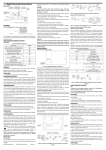
Wireless Thermostat Owners Manual
Model
A3918
LCD Display:Shows
Time,Day,Temperature,
and other feature
information as required.
Up and Down Key:Key for
changing the Temperature
setting. Also used for increasing
and decreasing selections in the
Time,Program,and Span
functions.
Reviews filter usage in hours and
minutes.
Also resets filter counter to zero.
Ste
p
Press
Button
1
PROG
2
PROG
INSTALLER/CONFIGURATION MENU
Displayed
Press up or
Comments
(Factory
down key
Default)
to select
SS1
SS1, HP2,
Selects Single stage, Multi-stage,
HP1
or Heat Pump (Single stage or
2-stage) System Configuration
(FAN)HE
HG
Select GAS/ ELECTRIC
3
4
5
6
7
PROG
PROG
PROG
PROG
PROG
RECO(OF)
(SPAN)2
BLIT(ON)
(SP2)2
(TEMP)F
(Only can select by STD2 or SS1)
Soft touch programming
and functions buttons (see below)
Front Door: To open or close
the door by pushing it softly
FEATURES
Structure of thermostat and explanation for the keypads
MODE
HOLD
/RUN
Selects the system mode
for Heat and Cool,Auto
heat, Emer,or Off.
FAN
For entering
day or time.
DAY/
TIME
Provides permanent temperature setting
by overriding stored programs. It also
returns the thermostat to current program
control from manual override or Home
Today mode. Returns display to current
time and temperature.
Fan key: For automatic or
continuous fan operation.
PROG
DAY
Selects the day or days to
review or change in Program
Mode.
PROG
Enters Program Mode
for reviewing and changing
weekday, weekend,or daily
programs.
We are pleased you have selected one of our broad line of wall thermostat. Our products
are manufactured to high quality standards and are designed for years of service.
REMOVE THE MYLAR LABEL FORM THE LCD DISPLAY WINDOW.
ARMCHAIR PROGRAMMING
1 You can program your thermostat before installation following the instructions starting
configuration menu. This can be done while you relax in your favorite chair and is a very
good way to familiarize yourself with all the functions of your thermostat.
The following time and temperature settings are pre-programmed into the thermostat:
Temperature in ˚F (˚C)
Program Number
Time
Heat
Cool
1
6:00 am
68˚F(20˚C)
78˚F(26˚C)
2
8:00 am
60˚F(16˚C)
85˚F(29˚C)
3
4:00 pm
68˚F(20˚C)
78˚F(26˚C)
4
10:00 pm
60˚F(16˚C)
82˚F(28˚C)
COMPRESSOR PROTECTION
2 The thermostat provides a 4 minutes delay after shutting of the heating or cooling
system before it can be restarted. This feature will prevent damage to your compressor
caused by rapid cycling. Note that this delay also applies to the heating system control. It
does not provide a delay when there are power outages. you can select the function on
or off at the configuration.
TEMPERATURE RANGE
3, This thermostat can be programmed between 45˚F and 95˚F (7˚C and 35˚C).
However, it will display room temperatures from 30˚F to 99˚F (0˚C and 37˚C). “HI” will be
displayed if the temperature is higher than 99˚F (37˚C), and “LO” will be displayed if the
temperature is lower than 30˚F (0˚C).This thermostat will automatically cutoff in Heat
mode if the temperature rises above 95˚F (35˚C), and automatically cutoff in Cool mode
if the temperature drops below 45˚F (7˚C).
POWER SUPPLY
8 The thermostat supply with Li-battery. You can charge the Lithium battery through
USB connect to PC.during the charge process.the battery icon will flash one by one.
Note: Lithium battery should be charged over 12 hours at the first 3 times to
ensure the battery capability.
INSTALLATION
What You Need
This thermostat includes two #8 slotted screws and two wall anchors for mounting. To
install your thermostat, you should have the following tools and materials.
■ Slotted Screwdriver(s)
■ Small Philips screwdriver
■ Hammer
■ Electric drill and 3/16” bit
Recovery function ON or OFF
Span(one stage)
BackLight
Span(Two Stage)
Selects temperature display ° F
or °C
8
PROG
HOUR(12)
24
Selects time format display
12hours or 24hours
9
PROG
COHP(OF)
ON
Selects Compressor Lockout
OFF or ON
10
PROG
CANL(1)
1-10
Communication channels
11
PROG
FACT(0)
1
Select 1,all the setting will go
back to factory default
The configuration menu allows you to set certain thermostat operating characteristics to
your system or personal requirements. Set SYSTEM mode to OFF, then simultaneously
press PROG keys to enter configuration menu. The display will show the first item in the
configuration menu. The configuration menu table summarizes the configuration options.
An explanation of each option follows .Press PROG key to change to the next menu item.
To exit the menu and return to the program operation, press Hold/Run Key. If no keys are
pressed within fifteen Seconds, the thermostat will revert to normal operation.
1)Single Stage, Multi-stage or Heat Pump System Configuration
This control can be configured for Heat Pump or two stage heat/one stage cool
multi-stage operation. The display indicates “STD2” (default for multi-stage mode) in the
display. The Multi-stage configuration can be toggled to “SS1”, or “HP1” by pressing the
up or down key. In Multi-stage configuration, EMER mode is useless.
2 This thermostat is configured from the factory to operate a heat/ cool, fossil fuel (gas,
oil, etc.), forced air system. It is configured correctly for any system that DOES NOT
require the thermostat to energize the fan on a call for heat. If you system is an electric
heat or heat-pump system that requires the thermostat to turn on the fan on a call for
heat, locate the HE/HG in the menu and SELECT it to the HE position. This will allow the
thermostat to energize the fan immediately on a call for heat. If you are unsure if the
heating/ cooling system requires the thermostat to control the fan, contact a qualified
heating and air conditioning service person. When the thermostat is configured for Heat
Pump, the thermostat will always power the circulator fan on a call for heat in the HEAT
mode. The HE/HG must be set to match the type of Auxiliary heat your system uses for
proper operation in the EMER gency mode.
All wiring diagrams are for typical systems only. Refer to equipment manufacturers’
instructions for specific system wiring information.
3) Select Energy Management Recovery OFF or ON
Your thermostat is set from the factory to gradually recover the room temperature from
an energy saving program to your comfort program. Therefore, the thermostat may turn
your system on several minutes prior to your programmed.
4)Fast or Slow Crycle Selection(one stage)
5)Select Backlight function OFF or on
6) Fast or Slow Crycle Selection(two stage)
7)Select °F or °C Readout. when you change this parameter. the programming come
back to fault. you have to set the programming again.
Changes the display readout to Centigrade or Fahrenheit as required
8) Selects time format display 12hours or 24hours
9)Select Compressor Lockout COMP OFF or ON
Selecting COMP ON will cause the thermostat to wait 4 minutes before turning on the
compressor if the heating and cooling system loses power. It will also wait 5 minutes
minimum between cooling and heating cycles. This is intended to help protect the
compressor from short cycling. Some newer compressors already have a time delay
built in and do not require this feature. Your compressor manufacturer can tell you if
the lockout feature is already present in their system. When the thermostat compressor
time delay occurs it will flash the set point for about four minutes.
10) This mode be use to setting commucation channels. The thermostat and controller
must be re-match when change the channales.
11) This model select 1 to back factory Default. The thermostat and controller must be
re-match.
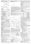
Setting Time And Day
Remove the mylar label covering the LCD display window before operating thermostat.
■ Initial display after power-up. The temperature will
update after a few seconds.
EXAMPLE: Set the Thermostat to the current time of 9:43 a.m. on
Saturday Refer to Figure at right
■ During time and day setting mode , the temperature
Press
Display Reads
Step 1
■Press Day/Time key. The current hour and AM or
DAY/
TIME
PM indicator areflashing.
■Press to change the hour.
Note AM/PM
Step 2
DAY/
TIME
Step 3
DAY/
TIME
ON
1,3
OF
1,3
C
■Press Day/Time key again.The current min is
flashing.
■Press to change the min.
■Press Day/Time key. The current week is flashing.
■Press to change the week.
OPERATION
Fan Operation
If your system does not have a G terminal connection, skip to Heating System System.
1. Turn on power to system.
2. Press FAN key to ON mode. The blower should begin to operate.
3. Move FAN key to AUTO mode. The blower should stop immediately
Heating System
1. Press system key until HEAT show LCD display. If the auxiliary heating system has a
standing pilot, be sure to light it.
2. Press to adjust thermostat setting to 1 above room temperature. The heating
system should begin to operate. The display should show “STG1”. However, if the
setpoint temperature display is flashing, the compressor lockout feature is operating
(see Configuration menu, item 5).
3. Adjust temperature setting to 3
above room temperature. If your system
configuration is set at MS2, HP2 or HP1, the auxiliary heat system should begin to
operate and the
display should show “STG1+2” 2”.
4. Press to adjust the thermostat below room temperature. The heating system should
stop operating.
Emergency System
EMER bypasses the Heat Pump to use the heat source wired to terminal E on the
thermostat. EMER is typically used when compressor operation is not desired, or you
prefer back-up heat only.
1. Press SYSTEM key to select Heat mode. then press EMER key.. “EMER” will show on
the display.
2. Press to adjust thermostat setting above room temperature. The Aux. heating system
will begin to operate. The display will show “STG1” “EMER” to indicate that the Aux.
system is operating.
3. Adjust temperature setting to 2°C above room temperature. The auxiliary heat system
should begin to operate and the display should show “STG1+2”.
4. Press to adjust the thermostat below room temperature. The Aux. heating system
should stop operating.
Cooling System
1. Press SYSTEM key to select the Cool mode.
2. Press to adjust thermostat setting below room temperature. The blower should come
on immediately on high speed, followed by cold air circulation. The display should show
“STG1”.
3. Adjust temperature setting to 2°C below room temperature. The second stage cooling
should begin to operate and the display should show “STG1+2”
4. Press to adjust the temperature setting above room temperature. The cooling system
should stop operating.
CONFIGURATION MENU
After 30 seconds, the thermostat will return to normal automatically.
Manual Programming
■ Your thermostat can be programmed for weekdays and weekends, or have unique
programs for all 7 days. Use Weekday /Weekend Programs or 7-day Programming to
enter or revise programs to match your Personal Program Schedule. The same steps
are used when entering programs for the first time, or revising programs entered during
Auto Programming.
■ Familiarize yourself with Manual Programming, so that you can easily modify your
programs as your comfort needs change. The example below demonstrates the Manual
Programming method.
NOTE:
1 The program time can be set in 10-minute increments, and remains the same for both
Heat and Cool programs.
2 The program temperature can be set in increments of 1˚F (1˚C).
3 The Heat setpoint can not be set higher than the Cool set point, and the Cool
set point can not be set lower than the Heat set point.
4 When setting the program time, note the AM/PM indicator.
5 With the Auto Recovery feature enabled, you do not need to set your comfort
program times early. Auto Recovery will determine how early Recovery will determine
how early to turn your system on, so that the room is comfortable at the program time.
Weekday/Weekend Programming
Weekday Programs
Press
Display Reads
■ Normal display of time, temperature,
and day of the week.
1
Step 1
Step 2
PROG
DAY
PROG
1
■
Step 3
PROG
■The Program hour and AM or PM indicator are
flashing. Press to change the hour.
1
■ Note AM/PM
Step 4
PROG
■Press again to change to the minute position. The
period minute will be flashing.
■ Press to change the minute
PROG
■ Press again to change to the program COOL set
temperature. The period program will be flashing.
■ Press to change the temperature.
■ Note HEAT/COOL
1
1
■ Press again to change to the program HEAT set
temperature. The period program will be flashing.
■ Press to change the temperature.
■ Note HEAT/COOL
Weekday program 1 is complete.
Step 6
Step 4
PROG
1
■ Press PROG to move to program 2,3, and 4 and follow the same steps.
Use
to insert or change time and temperature of other
Programs.
PROG
PROG
DAY
■Selects weekend days Sat, Sun for same set
of 4 programs each weekend day.
■ Follow steps 2-4 to enter programs.
Similar to weekday programming.
PROG
DAY
PROG
to insert weekend programs.
Similar to weekday programming.
PROG
DAY
to insert Individual programs.
PROG
NOTE: Another approach to programming is to first program all weekdays Mon
through Fir and Sat and Sun as same programs. Then, display and change the
programs of only those days which will have different programs.
Temporary Manual Override
To temporarily change the current set temperature without affecting your program:
■ Press up or down key for less than 1 second to enter Manual
Override mode..
■ Press up or down to change to your desired new temperature.
■ Press to RUN to normal mode or wait 20 seconds for it to
return automatically.
■ The current program number will flash to signify the Temporary Override.
HOLD
/RUN
At the next program change, the Temporary Override is canceled, and the next
program temperature becomes the setpoint temperature.
To end the Temporary Manual Override:
HOLD
/RUN
■ Press HOLD key twice. This will return the set temperature to the current
program set temperature.
NOTE: The Auto Season Changeover feature will not operate while the thermostats is
in Temporary Manual Override. Refer to the Auto Season Changeover feature for more
information.
Permanent Override or a Designated Day Override
To hold your Manual Override for vacation or Until a Designated Day.
■ Press to make the current program temperature the HOLD
HOLD
/RUN
temperature. HOLD will be displayed on the LCD, and the
Program number will disappear.
■ Follow the Temporary Manual Override instructions
above to change the Permanent Manual Override temperature.
HOLD
■ You can confirm the held set temperature by pressing for less than 1 second.
/RUN
■ Press again. Hold day will be displayed on the LCD and the clock
DAY/
will disappear
TIME
■ Press Day/Time key to adjust override days.
■ Follow the Permanent Override instructions above to change
the a Designated Day Manual Override temperature.
To end Override:
Under Permanent Override Press hold key twice. Under a Designated Day Override
press the hold once. The thermostat will return to the current program, and the HOLD
display will be canceled.
NOTE: The Auto Season Changeover feature will not operate while the thermostat is in
permanent Manual Override. Refer to the Auto Season Changeover feature for more
information.
Auto Season Changeover
When the System Selector is in AUTO position , the thermostat will automatically
change between Heating and Cooling systems, depending on your program. We
recommend keeping your programmed heating and cooling temperature at least 2˚F
(2˚C) apart to allow the Auto Season Changeover to occur when the appropriate
temperature span has been reached. However, if your heating and cooling programs set
temperatures are close, there is a built-in program to prevent the thermostat is in
Temporary, a Designated Day Override or Permanent Override, as these overrides are
energy saving settings. Auto Season Changeover will still function in Override mode, as
this is a comfort setting.
For example, you may have the following temperatures programmed at a given time:
Heat Set Temp=68˚F, Cool Set Temp=78˚F
If the room temperature rises above 78˚F, then the thermostat will automatically change
to cool mode and turn on the air conditioner.
Likewise, the thermostat will automatically change to heart mode and turn on heat when
the room temperature falls below 68˚F.
Filter Monitor
Your thermostat also keeps a record of the number of Days your filter has been in use.
To maximize your system’s performance and energy efficiency,change or clear your filter
regularly.
■ When the total fan run time reaches 400 hours, you need clean or
change your system’s filter, “FILTER” will continue to display until the
counter is set back to zero.
■ Press to review total filter usage. The “FILTER” display.
Then show the filter Monitor counter . After 20 seconds, the display will return to normal
mode, or you can hit RUN to exit immediately.
The Filter Monitor will display up to 100 Days of usage. In this example, the counter is
at10 Days.
■ To reset the Filter Monitor counter, depress FILTER for 3 seconds when the filter
monitor day show. The display will blink, and the counter will be reset to zero.
Auto Recovery
uto Recovery calculates how early to turn your system back on, so that the room
temperature is already comfortable by the start of the comfort temperature program
period. Auto Recovery work’s in both Heat and Cool modes.
■When the thermostat is in Auto Recovery mode, the display will
alternate “RECO” with time, and the program indicator will lcddisp.
■Auto Recovery can be disabled by menu setting.
■Auto Recovery will not operate if Permanent hold or Temporary hold is
in operation.
■Auto Recovery can be canceled manually if HOLD is pressed during the recovery
process.
■Auto Recovery will be canceled and change to next period.
Keyboard lock
The keyboard can be locked to prevent unauthorized changes to the thermostat.
To lock or unlock the keyboard, press and hold run Key for 3 seconds.
The keyboard is locked. when LOCK appears on the display.
■ All keys are locked, Any time a key is pressed, LOCK will appear on
the display for 1 second.
2
2
Error Mode
If the thermostat is unable to control your system due to an unexpected
problem, the thermostat will enter Error Mode. In this condition, the
thermostat flashes “E1”,“E2” on the LCD display, and shuts off your
system..
■ Selects days Mon to Fir for same set of 4
programs each day.
■ Program indicator(1) is displayed.
■Mon to Fir is displayed.
Step 5
1
Lcd display
information
Lcd display
information
E1
Sensor Error
E2
System switch
E
Low Battery Warning
Your thermostat has battery warning system. When the batteries are first
detected to be weak, the first stage low battery warning is indicated by
battery symbol flashing on the LCD display. At your earliest convenience,
you need to charge the batteries through USB. Duing Charge process the
battery icon will flash one by one.When the battery charge complete.the
battery icon will disappear.
1
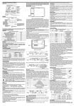
A3900 Series Controller manual
Key position
A3900 Series Controller
GENERAL
A3900 Series wireless sets is designed to control the room temperature in Industrial,
commercial and residential environment. It includes A3900 Series Wireless Thermostat
and A3900 Series Controller, by wireless data communication between thermostat and
controller, transfer
receive and carry out the control dictate and signal, and realize the
controlling of temperature.
off one transformer. If transformer safety circuits are in only one of the systems, remove
the transformer of the system with NO safety circuits. If required, replace remaining
transformer with a 75VA Class II transformer. After disconnecting one transformer, the
two commons must be connected together.
Use the terminal output information below to help you wire the thermostat properly for
your heat pump system. After wiring, see CONFIGURATION section for proper
thermostat configuration.
THERMOSTAT TERMINALS (HEAT PUMP)
SYSTEM
Heat Pump 1
Heat Pump 2
C*
24 Volt(Common)
R
24 Volt Emergency (hot)
E/W1
Emergency Mode 1st stage
W2
HP 1 and Emergency 2nd stage
Y1
Heat and Cool mode 1st stage (compressor)
Y2
No output
2nd stage compressor
G
Blower/Fan Energized on call for Heat and Cool
Set GAS/ELEC switch for Emergency mode
O
Energized in Cool Mode
B
Energized in Heat Emergency mode
WIRING
Cool only system
CONV. HP
B
O
Read This Before Installing controller
G
OPERATION
The A3900 Series Controller receive the signal from Wireless Thermostat without any
wires, and control cooling and heating equipment.
Controller
Y1
W2
E / W1
YOUR THERMOSTAT REPLACES
Description
Heat Pump (No Aux. or Emergency Heat)
Yes
Heat Pump (with Aux. or Emergency Heat)
Yes
Standard Heat & Cooling Systems
Yes
Two Stage Heat & Two Stage Cool
Yes
Standard Heat Only Systems
Yes
Millivolt Heat Only Systems– Floor or Wall
Yes
Furnaces
Standard Central Air Conditioning
Yes
Gas or Oil Heat
Yes
Electric Furnace
Yes
Hydronic (Hot Water) Zone Heat-2 Wires
Yes
Hydronic (Hot Water) Zone Heat–3 Wires
No
This Thermostat will NOT control 110/220Volt systems.
FAN RELAY
Y2
HEAT RELAY
NC
R
IN AC24V
C
Heat only system
CONV. HP
B
O
G
FAN RELAY
Y2
Controller
Y1
COOL RELAY
W2
E / W1
NC
R
POWER SUPPLY
The A3900 Series Controller shall be powered by 24 VAC.
MATCHING
The thermostat and controller will work only when they are match successful, and realize
1-1 control.
Step 1 (Controller): Power on the controller, press the match key for less than one
second (The key is on the right side of the controller, don’t press the key long). The
controller will receive the register matching data from the thermostat, user should finish
registration in 1 minute, if the controller haven’t received the matching dictate in 1 minute,
the controller matching data will come back to the data of last time automatically.
Step 2(Thermostat): Press “MODE” key to “OFF” mode, then press “PROG” key for 3
seconds until the screen changes to menu setting. Press “PROG” key until LCD display
“CRES”, use up key to change the parameter to “01” and thermostat will match
automatically.
Matching is finished.
IN AC24V
C
1-stage cooling , heating system for normal mode
CONV. HP
B
O
G
FAN RELAY
Y2
Controller
Y1
COOL RELAY
W2
E / W1
HEAT RELAY
NC
R
TESTING
Similar to menu setting.
Step 1 Press “PROG” key, until it displays “TEST”, change the parameter to “02” by
press up key , the relays will open one by one.
Step 2 Testing is finished, press “RUN” key to exit setting state, and the equipment could
work.
Note: This item is only for testing, not for normal output. if the wires be
connected .this test may be dangerous.
NOTE: The distance between the thermostat and controller should be long than
1m, if not it may fail communication. It should go back to the first step if the relay
don’t have output in the third step.
On the condition that thermostat and Controller haven’t matched, Controller
output testing: press the key (on the right side of the controller) and hold it over 3
seconds, relays will open and close one by one. Program will exit testing after thrice
circle. If user want to exit testing before three circle finished, press the key on the side for
3 seconds is OK.
IN AC24V
C
2-stage cooling , heating system for normal mode
CONV. HP
B
O
Controller
G
FAN RELAY
Y2
COOL RELAY 2
Y1
COOL RELAY 1
W2
HEAT RELAY 2
E / W1
HEAT RELAY 1
NC
R
IN AC24V
C
Technical Data
Power
Working environment
Range
Shell
Dimension
Connection interface
Wireless carrier wave frequency
Current
Communication baud rate
Wireless channels
Communication distance
AC24±5V 50/60Hz
0
50
5 95%RH(non-condensing)
Fire retardant PC ABS
116×98×45 mm HxWxD
Each terminal capable of accepting 2 x 1.5 mm2
or 1 x2.5mm2 wires electric heating type:1 x 4
mm2 wires
433MHz
28 mA
10 kbps
1~10 channels
Beeline distance 30m in the field(The distance will
shorten if through walls and floors)
1-stage cooling, heating system for heat pump
CONV. HP
B
CHANGE OVER VALVE
O
G
FAN RELAY
Y2
Controller
Y1
COMPRESSOR
W2
HEAT (AUX)
E / W1
EMER
NC
R
IN AC24V
C
COMPRESSOR PROTECTION
The thermostat provides a 4 minutes delay after shutting of the heating or cooling
system before it can be restarted. This feature will prevent damage to your compressor
caused by rapid cycling. Note that this delay also applies to the heating system control. It
does not provide a delay when there are power outages. you can select the function on
or off at the configuration.
2-stage cooling, heating system for heat pump
CONV. HP
B
CHANGE OVER VALVE
THERMOSTAT OUTPUT
Standard Terminal Outputs:
Refer to equipment manufacturers' instructions for specific system wiring information.
You can configure the controller for use with either multi-stage electric heat systems or
multi-stage gas systems. When configured for electric heat, the G terminal (blower/fan)
will be energized on a call for heat. This thermostat is designed to operate a
single-transformer system. If you have a two-transformer system, cut and tape off one
transformer. If transformer safety circuits are in only one of the systems, remove the
transformer of the system with NO safety circuits. If required, replace remaining
transformer with a 75VA Class II transformer. After disconnecting one transformer, the
two commons must be connected together. Use the terminal output information below to
help you wire the thermostat properly for your multi-stage system. After wiring see
CONFIGURATION section for proper thermostat configuration.
THERMOSTAT TERMINALS
SYSTEM
Single-stage
C*
24 Volt(Common)
R
24 Volt Emergency (hot)
E/W1
Heat mode 1st stage
W2
No output
Y1
Cool Mode 1st stage
Y2
No output
G
Blower/Fan Energized on call for
Electric Heat)
O
No output
B
No output
O
Controller
G
FAN RELAY
Y2
COMPRESSOR 2
Y1
COMPRESSOR 1
W2
HEAT (AUX)
E / W1
EMER
NC
R
C
IN AC24V
INSTALLATION
Installation guide
Multi-stage
Heat Mode 2nd stage
2nd stage compressor
Cool (and Heat if configured to
Heat Pump Terminal Outputs
Refer to equipment manufacturers' instructions for specific system wiring information.
You can configure the thermostat for use with the following heat pump system types:
Single stage compressor system; gas or electric backup. This thermostat is designed to
operate a single-transformer system. If you have a two-transformer system, cut and tape
What You Need
This thermostat includes two #8 slotted screws and two wall anchors for mounting. To
install your controller, you should have the following tools and materials.
■ Slotted Screwdriver(s)
■ Small Philips screwdriver
■ Hammer
■ Electric drill and 3/16” bit
CAUTION:
To prevent electrical shock and/or equipment dam- damage, age, disconnect
electric power to system at main fuse or circuit breaker box until installation is
complete.
WARNING
Do not use on circuits exceeding specified voltage. Higher voltage will damage
control and could cause shock or fire hazard. Do not short out terminals on gas
valve or primary control to test. Short or incorrect wiring will damage thermostat
and could cause personal injury and/or property damage.
TROUBLESHOOTING
Problem
SCRAMBLED OR
DOUBLE DISPLAY
(numbers over
numbers)
NO DISPLAY
ENTIRE DISPLAY
DIMS
PROGRAM DOES
NOT CHANGE AT
YOUR DESIRE
SETTING
AUTO/FAN DOES
NOT TURN ON
Solution
1.Remove clear mylar sticker.
1.Charge Li-battery
1.Charge Li-battery
1.Check that the time is set properly to “AM” or “PM”
2.Check that the thermostat is not in “HOLD” mode.
3.Check for the correct day settings.
1.Change HE/HG parameter to opposite setting .
2.The thermostat may be in the AUTO Mode. Look
for ”AUTO” on the LCD display. If the Heat and Cool
program temperature are close, then the thermostat
requires a larger room temperature change before
changing from Heat or Cool.
3. There may be as much as 4 minute delay before the
Heat or Cool system
turns On-wait and check.
(Compressor protection delay).
4 Check your circuit breaks and switches to ensure there
is power to the system.
6. Make sure your furnace blower door is closed properly.
ERRATIC DISPLAY
1.Replace unit.
CONTROLLER
NO
1.Check if the thermostat is working, if the thermostat is
OUTPUT
effective, and if the power is supplied to the controller.
2.Check if the communication is correct, the controller will
close all the relays if there is no data received in 30
minutes.
3 Match the thermostat and the controller again.
COMMUNICATION
1. Check if the thermostat is working, if the therpstat is
FAILED
effective, and if the power is supplied to the controller.
2.The distance between the thermostat and controller
should be longer than 1m, shorter than 100m in the field.
3 Match the thermostat and the controller again.
If you experience any other problems, call us for technical assistance.