1
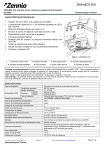
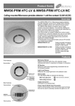
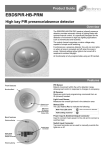
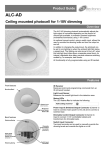
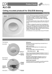
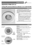
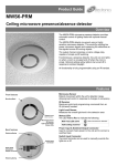
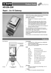
Product Guide ALC-PRM-VFC Ceiling Mounted Photocell Overview The ALC-PRM-VFC photocell will turn lighting on when the ambient light falls below a preset level. The lighting will then be turned off when the total light level rises above a separate preset level. The unit also has a switch input for manual override. An integral, adjustable time delay prevents nuisance switching caused by, for example, dark clouds. The unit has a voltage free changeover output which can be used to switch, a BMS or lighting control system as well as switching a load directly. All functionality is fully programmable using an IR handset. Features Front features IR Receiver Receives control and programming commands from an IR (infrared) handset. Mounting Bezel Light Level Sensor Measures the overall light level in the detection area Status LEDs The LED flashes Red to indicate the following: Sensor Lens which covers... IR Receiver Light Level Sensor Status LEDs Back features Retaining Spring Power Input Connector Switched Output Connector Retaining Spring Valid setting received Power Connector Used to connect mains power to the unit. Switched Output Connector Used to connect a switched load. Installation Choosing a Suitable Location The ALC-PRM-VFC is designed to be ceiling mounted and must satisfy the following criteria: Avoid positioning the unit where direct sunlight may enter the sensor element. Wiring Diagram - Mains load Wiring Diagram - Volt Free Contact Sensor functionality Switch Level On/Off The device can be made dependant on the ambient light level using the Lux On Level and Lux Off Level parameters. Fault finding What if the load does not turn ON? Check that the live supply to the circuit is good. Increase the Lux on level to switch on at a higher brightness . What if the load does not turn OFF? Increase the lux off level to switch off at a lower brightness. Load cycles on and off Increase the difference between the lux on level and the lux off level. Increase the time setting. Angle the sensor away from the light that it is controlling. 2 Installation The ALC-PRM-VFC is designed to be mounted using either: Flush fixing, or Surface fixing, using the optional Surface Mounting Box (part no. DBB). Both methods are illustrated below. Flush Fixing 1 Hole Ø64mm 2 3 4 2 3 4 Warning - be careful bending springs when mounting unit. Surface Fixing 1 50mm or 60mm fixing centres Pull out spring tab and rotate spring arm as shown Wire stripping details Important Ensure that the cables are formed as shown before affixing the cable clamp. The clamp MUST clamp the outer sheath(s) only. Bend cores as shown. Readback function (UNLCDHS handset only) The UNLCDHS has the ability to read back the settings stored in a device. To read back individual parameters Navigate to the parameter and press the „R‟ (Read) button whilst pointing at the device. The handset will click when the parameter has been read back, the device will flash its LED, and the value will be shown against the parameter in the menu. To read back all of the parameters in a menu Press and hold the „R‟ (Read) button for more than 1 second. The handset will click every time a parameter is received The device will show multiple flashes of its LED All of the values will be shown against the parameters in the menu. The individual parameters may be edited and then saved as a „Macro‟. Notes If a parameter(s) has been missed because of a communication error, the missing value(s) is replaced by dashes. When reading back, the relay will temporarily be switched off, and will return to it’s normal state 2 seconds after the read back has been completed. 3 Basic programming The functionality of the ALC-PRM-VFC is controlled by a number of parameters which can be changed or programmed by any of the following devices: UHS5 Infrared Handset. See below for programmable functions. UNLCDHS Infrared Handset (with LCD). See user guide for full programming details. For most basic programming operations the UHS5 handset can be used and the following procedures are based on using this device. Point the handset at the Sensor and send the required programming commands to the unit as shown below. Valid commands will be indicated by a red LED flash. See page 1 for details of other LED responses. Note: other functions on the UHS5 which are not shown below are not applicable to this product. Number of Shift key presses Parameter Name Default Value 0 SHIFT 1 1 SHIFT 2 SHIFT 1 2 SHIFT 2 SHIFT 1 3 SHIFT 2 SHIFT 1 UHS5 Handset Graphics Description SHIFT 2 Button Activation On On Turn lights on. Off Off Turn lights off. Lux on level (Switch level on) 9 2, 5 & 7 4, 6 & 9 Lux level setting to prevent the luminaires being switched on if the ambient light level is sufficient (adjustable between 1 and 9). The luminaires will always be switched on at level 9. Lux off level (Switch level off) 9 2, 5 & 7 4, 6 & 9 Lux level setting to switch the luminaires off the ambient light level goes above the setting (adjustable between 1 and 9). Level 9 will always keep the lights on. This setting can be used for “window row switching”. Note: the Lux Off Level value must always be greater than the Lux On Level value. Defaults Shift 4 D Returns the unit to the default settings. Use this button to select the settings in red and blue signified by the „Shift 1‟ and „Shift 2‟ LEDs Advanced programming Parameter Name Default Value UHS5 UNLCDHS Range / Options Description 0 (disabled) 1-99 minutes To prevent nuisance switching, an adjustable time delay can be set. This requires the light level to be maintained for the set time before changing from on to off, or off to on. Restores factory default settings Detector Parameters Lux time 0 Factory default - - Switching functions Lux on level (Switch level on) 9 1 to 9 For a higher resolution a scale of 101-199 is available Lux level setting to prevent the luminaires being switched on if the ambient light level is sufficient. Note: the Lux Level Off value must always be greater than the Lux Level On value. Lux off level (Switch level off) 9 1 to 9 For a higher resolution a scale of 101-199 is available Lux level setting to switch the luminaires off the ambient light level goes above the setting. User Modes Override On - - If the lights are off, sending the IR command will turn them on immediately and revert to automatic operation using the manual timeout period . Override Off - - If the lights are on, sending the IR command will turn them off immediately. After the manual timeout period (described above), the sensor will revert to automatic. Cancel - - Cancels the on or off override, returning the unit to normal operation. 5 This page intentionally left blank 6 This page intentionally left blank 7 Technical data Dimensions Weight Supply Voltage Frequency Maximum Load See diagrams opposite 0.1kg 230VAC +/- 10% 50Hz Power consumption On 745mW, Off 264mW Terminal Capacity Temperature Humidity Material (casing) Type IP rating 2.5mm2 -10ºC to 35ºC 5 to 95% non-condensing Flame retardant ABS and PC/ABS Class 2 IP40 Compliance EMC-2004/108/EC LVD-2006/95/EC ALC-PRM-VFC 10 Amp resistive and incandescent lighting 6 Amp fluorescent lighting and resistive 3 Amp compact fluorescent lighting 3 Amp low energy lighting 3 Amp low voltage lighting (switch primary of transformer) Fluorescent lighting (max 6 fittings recommended) For fluorescent lighting total power factor correction capacitance must not exceed 40μF. 3 Amp fans and ventilation equipment Switch SON lighting loads via a contactor Minimum load 100mA DBB Part numbers Detector Accessories Part number ALC-PRM-VFC DBB UHS5 UNLCDHS Description Ceiling Mounted Photocell Surface mounting box Programming IR handset Universal LCD IR handset IMPORTANT NOTICE! This device should be installed by a qualified electrician in accordance with the latest edition of the IEE Wiring Regulations and any applicable Building Regulations. FM 45789 EMS 534520 Due to our policy of continual product improvement CP Electronics reserves the right to alter the specification of this product without prior notice. 8 C.P. Electronics Ltd Brent Crescent London NW10 7XR United Kingdom Tel: + 44 (0) 333 900 0671 Fax: + 44 (0) 333 900 0674 www.cpelectronics.co.uk [email protected] Ref: #WD484 Issue 1