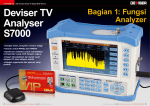
1
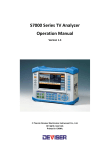
User Guide E7000 Series Cable & Antenna Analyzer Model E7000A E7000A-SA E7100A E7100A-SA Cable&Antenna A l Spectrum 4.4GHz 4.4GHz 6.1GHz 6.1GHz l Transmission l 3GHz 3GHz 3GHz 3GHz Ver:1.08 E7000 Series Cable & Antenna Analyzer User Guide Conventions This manual has the following conventions for presenting information. WARNING: A warning alerts you to any condition that could cause personal injury. CAUTION: A caution alerts you to any condition that could cause a mechanical failure or potential loss of data. Make sure the AC power supply voltage meet the equipment requirements, otherwise it will cause a equipment failure. Make sure to plug the power cable into an electrical outlet that has a safety grounding before turning on the power switch. Touch the internal circuit may cause a mechanical failure or personnel injury, so only trained engineer can remove the instrument cover and maintain the instrument. Guarantee This instrument is guaranteed for a period of 12 months from the date of shipment. Under warranty, any fault not caused by improper use will be repaired for free. Liability of the user: Use this instrument according to this instruction manual. When this instrument need to be repaired, please send it back to our company or our appointed repair center. The guarantee is limited only to the instrument and does not involve any damage of equipment, personnel and property caused by improper use of the instrument. -1- E7000 Series Cable & Antenna Analyzer User Guide Limitation of Guarentee The warranty is not applicable for the faults resulted by improper use or inadequate maintenance (including software or interface), and unauthorized open of the instrument. Within the 12 months warranty period, calibration, maintenance service and consultation shall be free. After the 12 months warranty period, fees for material and repair workman will be charged appropriately. The following items are not under warranty: A. Damage caused by improper voltage input. B. Deformation or damage of panel, switches, devices and case as well as defects involving interval parts caused by external mechanical force (shocking and dropping, etc.). C. Defects caused by unauthorized repair. D. Defects caused by the instrument worked beyond the required technology specification. Updates Updates, if any, can be downloaded from the Deviser web site at:http://www.devisertek.com Deviser Part No.: DK11820E7000 © Tianjin Deviser Electronics Instrument Co., Ltd. All rights reserved. Printed in CHINA. May 2012. -2- E7000 Series Cable & Antenna Analyzer User Guide Table of Contents 1 General Information ............................................................................. 1 1.1 1.2 1.3 1.4 1.5 1.6 1.7 1.8 1.9 2 Instrument Overview ............................................................................ 7 2.1 2.2 2.3 2.4 2.5 2.6 2.7 2.8 3 Introduction ......................................................................................... 2 Available Models .................................................................................. 2 Available Options ................................................................................. 3 Standard Accessories ........................................................................ 3 Preventive Maintenance ...................................................................... 4 Calibration Requirements&Annual Verification ...................................4 ESD Caution .......................................................................................... 4 Battery Replacement............................................................................ 5 Soft Carrying Case ................................................................................ 6 Turning On the instrument................................................................... 8 Front Panel Overview ........................................................................... 9 Test Panel Connector Overview ......................................................... 13 Display Overview ................................................................................ 15 Menu Operation ................................................................................. 16 Symbols and Indicators ...................................................................... 18 Data Entry........................................................................................... 20 Mode Selector Menu.......................................................................... 20 Quick Start Guide................................................................................ 22 3.1 Introduction ....................................................................................... 22 3.2 Cable & Antenna Analyzer mode ....................................................... 22 3.3 Spectrum Analyzer ............................................................................. 26 4 File Management ................................................................................ 31 4.1 4.2 4.3 4.4 4.5 4.6 4.7 Introduction ....................................................................................... 31 Managing Files ................................................................................... 32 File Menu Overview ........................................................................... 34 File Menu ........................................................................................... 35 Recall Menu........................................................................................ 36 Copy Menu ......................................................................................... 37 Delete Menu ...................................................................................... 38 -3- E7000 Series Cable & Antenna Analyzer User Guide 4.8 Files type ............................................................................................ 39 5 System Operations ............................................................................. 40 5.1 Introduction ....................................................................................... 40 5.2 System Menu Overview ..................................................................... 40 5.3 System Menu ..................................................................................... 42 5.4 System Options Menu ........................................................................ 43 5.5 Display Setup Menu ........................................................................... 45 5.6 System Test Menu .............................................................................. 47 5.7 System Upgrade Menu ....................................................................... 48 5.8 Help Menu .......................................................................................... 49 5.9 Print Menu ......................................................................................... 51 5.10 Select Printer Menu ........................................................................... 52 6 Software Tool ..................................................................................... 53 6.1 6.2 6.3 6.4 7 Introduction ....................................................................................... 53 Feature Overview ............................................................................... 53 Install Site Workbench ....................................................................... 54 Connecting to the Instrument ............................................................ 54 Specifications ..................................................................................... 55 7.1 Cable & Antenna Analyzer.................................................................. 55 7.2 Spectrum Analyzer ............................................................................. 56 -4- E7000 Series Cable & Antenna Analyzer User Guide 1 General Information This chapter provides information about the following items. ● Introduction ● Available Models ● Available Options ● Standard Accessories ● Preventive Maintenance ● Calibration Requirements&Annual Verification ● ESD Caution ● Battery Replacement ● Soft Carrying Case ● Technical Support and Service Information 1 E7000 Series Cable & Antenna Analyzer User Guide 1.1 Introduction E7000 Series Cable & Antenna Analyzer with integrated spectrum analyzer , reduces per site maintenance expense, maximizes system up-time, and breaks away from the traditional fix-after-failure maintenance mode by finding small problems before major failures occur. E7000 Series performs various RF measurements aimed at simplifying cable feedline and antenna analysis: Return Loss, SWR, Cable Loss, Distance-to-Fault (DTF), 1-port phase and smith chart. The E7000 is an integrated multi-functional analyzer that eliminates the need to carry and learn multi instrument. The E7000 is a cable & antenna analyzer that can be configured to include 3 GHz spectrum analyzer, 2-port Transmission Measurement with a bias tee, and a High Accuracy GPS receiver for location stamping. The bright 6.5-inch color display provides visibility even in broad daylight. Built-in Li-Ion battery can work more than 4.5 hours. Even with “spectrum analysis” option, the working time is still more than 3 hours. The internal 1G flash memory is large enough to store approximately 2,000 traces or setup files. Measurements data and setup files can also be stored in a USB flash disk or transferred to PC via the LAN cable. Site Workbench, a PC based software program, provides a simple and easy way to manage, archive, analyze and print measurement reports, customize your cable list, antenna list and signal standards list . 1.2 Available Models Table1-1 lists the E7000 models and frequency ranges described in this User Guide. Model E7000A E7000A-SA E7100A E7100A-SA Cable&Antenna 4.4GHz 4.4GHz 6.1GHz 6.1GHz Spectrum Analyzer 2 3GHz Table 1-1. Available Models 3GHz E7000 Series Cable & Antenna Analyzer User Guide 1.3 Available Options E7000 E7100 Description E7000-0010 E7100-0010 Transmission Measurement E7000-0030 E7100-0030 GPS receiver(Including antenna) Table 1-2. Available Options 1.4 Standard Accessories .Part Number Description E7000-0100 User Guide E7000-0110 Quick Guide C50N-P N(male) type standard calibration kits NP-DL01-NJ-150 1.5m N(male)-N(female) type RF cable E7000-0200 CD : Site Workbench Software E7000-0300 11.1V /5.2Ah Rechargeable Li-Ion Battery PW31188821Q FSP065-R AC Adapter E7000-0400 Vehicle charger E7000-0500 USB A/5-pin mini-B Cable P.310015000 Crossover LAN cable E7000-0600 Soft Carrying Case P.110829NJK L29(female)-N(male) Adapter Table 1-3. Standard Accessories 3 E7000 Series Cable & Antenna Analyzer User Guide 1.5 Preventive Maintenance E7000 series preventive maintenance include the unit surface cleaning, RF connectors and all accessories cleaning. Clean unit surface with a soft, lint-free cloth dampened with water. NOTICE:To avoid damaging the display or case, do not use solvents or abrasive cleaners. Clear the RF connectors and center pins with a cotton swab dampened with denatured alcohol. The fingers of the N(f) connectors and the pins of the N(m) connectors should be unbroken and uniform in appearance. If you are unsure whether the connectors are undamaged, gauge the connectors to confirm that the dimensions are correct. The test port cable should be uniform in appearance, and not stretched, kinked, dented, or broken. 1.6 Calibration Requirements&Annual Verification Local service centers are responsible for instrument maintenance and calibration once a year. To ensure performance conformity.Deviser recommends a periodical maintenance and calibration. The Cable & Antenna Analyzer is calibrated with OPEN, SHORT, LOAD calibration components. It is especially important to verify the OSL calibration components periodically to ensure performance conformity. 1.7 ESD Caution E7000 series, like other high performance instruments, is susceptible to electrostatic discharge (ESD) damage. Coaxial cables and antennas often build up a static charge, which may damage the E7000 input circuitry. E7000 operators must be aware of the potential for ESD damage and take all necessary precautions. It is recommended to discharge the static by connecting a short or load device to the cable or antenna before connecting them to E7000. It is important to remember that the operator may also carry a static charge that can cause damage. Following the practices outlined in the above standards will ensure a safe environment for both personnel and equipment. 4 E7000 Series Cable & Antenna Analyzer User Guide 1.8 Battery Replacement The battery can be replaced without the use of any tool. The battery compartment is located on lower side of rear (when you are facing the measurement display). Wring out two screws, slide the cover down and remove the battery. Installation is the opposite of removal. NOTE:When inserting the battery, the battery label should face the back of the instrument and the guide slot on the battery should be below the contacts. If the battery door does not latch ed, the battery may be inserted incorrectly. Figure1-1. Battery Compartment Door NOTE : Use only batteries, adapters, and chargers provided with this instrument. CAUTION:When using the Vehicle charger, Make sure that the supply is rated for a minimum of 60 Watts at 12 VDC, and the socket is clean without any dirt or debris. If the adapter plug becomes hot to the touch during charging, Please discontinue use immediately. NOTE:Deviser recommends removing the battery for long-term storage of the instrument. 5 E7000 Series Cable & Antenna Analyzer User Guide 1.9 Soft Carrying Case The E7000 can be operated while in the soft carrying case. On the back of the case is a large storage pouch for accessories and power supply. Figure1-2. Instrument Inserted into the Soft Carrying Case To install the instrument into the soft carrying case: 1. The front panel of the case is secured with hook-and-loop fasteners. Fully close the front panel of the case. When closed, the front panel supports the shape of the case while you are inserting the E7000. 2. Place the soft carrying case face down on a stable surface, with the front panel fully closed and laying flat. NOTE:The soft case has two zippers near the back. The zipper closer to the front of the case opens to install and remove the instrument. The zipper closer to the back of the case opens an adjustable support panel that can be used to provide support for improved stability and air flow while the instrument is in the case. This support panel also contains the storage pouch. 3. Open the zippered back of the case. 4. Insert the instrument face down into the case, take care that the connectors are properly situated in the case top opening. You may find it easier to insert the connectors first, then pull the corners over the bottom of the E7000. 6 E7000 Series Cable & Antenna Analyzer User Guide 2 Instrument Overview This chapter provides a brief overview of the E7000 Series Cable & Antenna Analyzer. The intent of this chapter is to acquaint the user with the instrument. For detailed measurement information, refer to a specific measurement guide listed in “Measurement Guides”. This chapter provides information about the following items ● Turning On the instrument ● Front Panel Overview ● Test Panel Connector Overview ● Display Overview ● Symbols and Indicators ● Data Entry ● Mode Selector Menu 7 E7000 Series Cable & Antenna Analyzer User Guide 2.1 Turning On the instrument The Deviser E7000/E7100 models are capable of approximately 4.5 hours and the E7000SA/E7100SA models are capable of approximately 3 hours of continuous operation from a fully charged, field-replaceable battery. The E7000 Series can also be operated from a 12 Vdc source (which will also simultaneously charge the battery). This can be achieved with either the AC-DC Adapter or Automotive Cigarette Lighter Adapter .Both items are included with the instrument. CAUTION:When using the Vehicle charger, Make sure that the supply is rated for a minimum of 60 Watts at 12 VDC, and the socket is clean without any dirt or debris. If the adapter plug becomes hot to the touch during charging, Please discontinue use immediately. Main Keys Function Sub-Menu Keys Fan Exhaust Port Fan Inlet Port Numeric Keypad /Measurement function Keys Main Menu Keys Backlight Control On/Off Button Figure 2-1. E7000 Overview To turn on the instrument, press the red On/Off button for 2s on the front panel (Figure2-1). The instrument takes approximately twenty seconds to complete power warm-up and to load the application software. At the completion of this process, the instrument is ready for use. 8 E7000 Series Cable & Antenna Analyzer User Guide 2.2 Front Panel Overview The E7000 Series menu-driven interface is easy to use and requires little training. The E7000 uses the keypad for data input. The five main menu keys below the screen and eight submenu keys on the right side are menu keys. Function keys on the right, consist of six main function keys and twelve measurement function keys.The twelve measurement function keys are dual purpose, depending upon the current mode of operation.The dual-purpose keys are labeled with a number on the key itself and the alternate function is printed in black below each of the keys. Numeric keys are active in parameter edit mode, otherwise measurement function keys are active . Note :Keep the fan inlet and exhaust ports clear of obstructions at all times for proper ventilation and cooling of the instrument. Main Menu Keys Five main menu keys are below the display screen. MODE Press the key then select a measurement mode by pressing the corresponding sub-menu key. NOTE :Available mode selections will vary according to model number and options installed. FREQ/DIST Displays the Frequency or Distance to Fault soft key menus depending on the measurement mode. AMPTD Displays the amplitude soft key menu for the current operating mode. MEAS Displays the measurement soft key menus for the current operating mode. MARK Displays the marker soft key menus for the current operating mode. 9 E7000 Series Cable & Antenna Analyzer User Guide Sub-Menu Keys There are eight keys that change function depending upon the current mode selection. The current key function is indicated in the soft key menu area on the right side of the screen. Main Function Keys There are six main function keys on the top of the panel. FILE Active the file management function to use for saving or recalling the setup files, measurement files and graphics files. SYS Allow selection of system and application setup parameters, the display language , system upgrade and printing etc.. CAL Starts the calibration in SWR, Return Loss, Cable Loss, or DTF measure -ment modes (not available in Spectrum Analyzer or Power Meter modes). HOLD When in the Hold mode, this key starts the E7000 sweeping and provides a Single Sweep Mode trigger; when in the Continuous mode, it pauses the sweep. When in the Hold mode, the hold symbol appears on the display. ESC Exits the present operation or clears the status window. If a parameter is being set, pressing this key will clear the value currently being entered and restore the last valid entry. Pressing this key again will close the parameter. ENTER Press this key to finalize data input or select a highlighted item from a list. 10 E7000 Series Cable & Antenna Analyzer User Guide Measurement Function Keys Measurement function keys are active when the instrument is not in parameter edit mode. SWEEP Press this key to set sweep type, points, RF immunity, RBW, data averaging and data smoothing etc. TRACE Manipulating the trace menu enables you to find the difference between the active trace and a saved trace or to do data math,etc. LIMIT Display the limit line menu for the current operating mode when in cable and antenna analyzer or spectrum analyzer mode. SAVE STP Save the current system setup to an internal memory location. When the key is pressed, a Setup File Name appears. Use the numeric keys to enter characters for the setup file name and press the ENTER key to implement. RECALL STP Recall a previously saved setup from a memory location. When the key is pressed, a Setup File selection box appears on the display. Select a setup using the Up/Down arrow key and press the ENTER key to implement. SAVE MEAS Save displayed traces to memory. When the key is pressed, the Measurement File Name appears. Use the numeric keys to enter characters for the measurement file name and press the ENTER key to save the trace. RECALL MEAS Recall a previously saved trace from memory. When the key is pressed, a Measurement File selection box appears on the display. Select a trace using the Up/Down arrow key and press the ENTER key to implement. 11 E7000 Series Cable & Antenna Analyzer User Guide VSWR Implement the VSWR measurement. RETURN LOSS Implement the RETURN LOSS measurement. CABLE LOSS Implement the CABLE LOSS measurements. DTF VSWR Implement the DTF–VSWR measurement. DTF RL Implement the DTF–Return Loss measurement. “↑ ↓” Arrow Keys The arrow keys can often be used to change a value or to change a selection from a list. This function is similar to the function of the rotary knob. The arrow keys are also used to move markers. Rotary Knob Turning the rotary knob changes numerical values, scrolls through selectable items from a list, and moves markers. Values or items may be within a dialog box or an edit window. Pressing the Rotary Knob is used as “ENTER” key. Number Keypad The Number keypad has two functions: The primary function is number entry. The secondary function of the number keypad is to list various menus or to implement various measurements. LED Indicators Charging LED, is located on the test panel, the LED is red when the battery is charging and is green when the battery is fully charged. The Power LED, is located to the right of the On/Off key, the LED is green when the unit is on. 12 E7000 Series Cable & Antenna Analyzer User Guide 2.3 Test Panel Connector Overview The connectors and indicators located on the test panel (Figure 2-2) are listed and described below. USB Mini-B Type LAN port External USB A-Type Power Supply DC Out RF Output RF Input Figure2-2 E7000 Test Panel Connector External Power The external power connector is used to power the unit and for battery charging. Input is 12.5 VDC to 19 VDC at up to 3.42A. USB Interface - Type A The E7000 has a Type A USB connectors that accept USB Flash Memory devices for storing measurements, setup data, and screen images, or a GPS modual. USB Interface - Mini B The USB 2.0 Mini-B connector can be used to connect to a PC. LAN port The LAN port is used to connect to a PC loaded the Site Workbench software providing a simple and easy way to manage, archive, analyze, print measurement reports, customize your cable list, antenna list, signal standards list. 13 E7000 Series Cable & Antenna Analyzer User Guide RF In 50ΩType-N female connector. Maximum input is +30 dBm at ±50 VDC. RF Out/Reflection In RF output, 50Ωimpedance, for reflection measurements. Maximum input is +25 dBm at ±50VDC. 14 E7000 Series Cable & Antenna Analyzer User Guide 2.4 Display Overview Figure 2-3 describes Antenna measurement mode, DTF – the return loss measurement type at some of the important information. Parameter Setting Frequency standard Trace Title Test Result Indicatoin Mode Hold Icon Measurement Type LAN USB Battery Charge Submenu Calibration Status,Type Measurement Settings Summary Marker Table Note information GPS Location Date/Time Figure 2-3 Cable&Antenna Analyzer DTF-VSWR Measurement Display 15 E7000 Series Cable & Antenna Analyzer User Guide 2.5 Menu Operation There are 7 typical menus and each is described below in detail. Setting Parameters Press the corresponding menu, and the parameter shows in the middle of the screen. Use the numeric keys, arrow keys or Rotary Knob to set the parameter,and press the Enter key to exit. Two functions switch Press the corresponding menu button to switch the two functions. Enter the next submenu (no parameter) Press the corresponding menu key, enter the next submenu. Enter the next submenu (with parameters) Press the corresponding menu key,enter the next submenu to select an option, and then return to the previous menu automatically. 16 E7000 Series Cable & Antenna Analyzer User Guide Implement the menu function Press the menu key corresponding function. to implement the Select to implement function Press the menu key and select a submenu to implement the corresponding function and then return to previous menu. No operation Some of the menu are available that have to be right state. No opration When the menu grays out 17 E7000 Series Cable & Antenna Analyzer User Guide 2.6 Symbols and Indicators The following symbols and indicators indicate the instrument status or condition on the display. Calibration Symbols The current calibration status and type is displayed when in Cable & Antenna Analyzer mode. ☆ Calibration status OFF The E7000 has not been calibrated. ☆ Calibration status Full Span ON The E7000 has been calibrated with discrete Open, Short, and Load components. This is a Full Span calibration indicating it is possible to change the frequency range and trace points after calibration. ☆ Calibration status Standard ON The E7000 has been calibrated with discrete Open, Short, and Load components. This is a Standard calibration indicating it is possible to change trace points , but it is impossible to change the frequency range after calibration without performing another calibration. Battery Symbols ☆ Green: Battery is 30% to 100% charged ; ☆ Yellow: Battery is 10% to 30% charged ; ☆ Red: Battery 0% to 10% charged ; ☆ Lightning Bolt: Battery is being charged. When either the AC-DC Adapter or the 12 VDC adapter is connected, the battery automatically receives a charge, and the battery symbol with the lightning bolt is displayed . Caution: Use only use batteries, adapters, and chargers provided with this instrument. 18 E7000 Series Cable & Antenna Analyzer User Guide When operating from external power without a battery installed, the battery symbol is replaced by a plug body, as shown in Figure 2-4. Figure 2-4 Battery Not Installed Other Symbols ☆ Network Connection: The instrument is communicating with PC via the LAN port ☆ USB connection: The usb device is busy for data exchange; ☆ Hold: The measurement pauses and the trace is not refreshed 19 E7000 Series Cable & Antenna Analyzer User Guide 2.7 Data Entry Parameter Setting You can set parameters with the numeric keys,the arrow keys and the rotary knob. It is simple to change the parameters quickly with the arrow keys.. You can change the parameter continuously with the rotary knob. Edit in position displayed On a measurement display, Many parameters are listed in place.You can move the highlight cursor at the place where a parameter shows,and press the Enter key to begin setting. The numeric keys, arrow keys and the rotary knob can be used to set the parameter. Press Enter to exit. Submenu Entry When pressing the corresponding submenu key ,Parameter shows on the upper left corner of the display。You can set the parameter using the numeric keys, arrow keys or the rotary knob, and press Enter to exit the editor. Text Entry When saving a Measurement,a Setup or a BMP file, you have to enter the characters and numbers to name it. 2.8 Mode Selector Menu Press the "MODE" hard key to enter the measurement mode selection display (Figure 2-5).You can select the desired measurement mode, or enter the next level menu. You can also press the shortcut measurement function keys at the bottom of the keypad to implement the measurement. NOTICE:The measurement mode depends on the E7000 model and installed options. Refered to Table 1-1 and Table 1-2. 20 E7000 Series Cable & Antenna Analyzer User Guide Figure 2-5 Measurement Mode Selection 21 E7000 Series Cable & Antenna Analyzer User Guide 3 Quick Start Guide 3.1 Introduction This chapter provides a brief overview of the E7000's basic measurement setup. 3.2 Cable & Antenna Analyzer mode Set the instrument to Cable & Antenna Analyzer mode as described in the previous section. Select the Measurement Type Press the MEAS main menu key and select the appropriate measurement. Shown in Figure 3-1 Figure 3-1 Select the Measurement Type 22 E7000 Series Cable & Antenna Analyzer User Guide Set the Frequency 1. Press the FREQ DIST main menu key. 2. Press the Start Freq submenu key and use the keypad, rotary knob, or the arrow keys to enter the start frequency. 3. Press the Stop Freq submenu key and use the keypad, rotary knob, or the arrow keys to enter the stop frequency. Set the Amplitude 1. Press the AMPTD main menu key. 2. Press the Top submenu key and use the keypad, rotary knob, or the arrow keys to edit the top scale value. Press Enter to set. 3. Press the Bottom submenu key and use the keypad, rotary knob, or the arrow keys to edit the bottom scale value. Press Enter to set. Set the amplitude in Auto Scale mode In Auto Scale mode, the measurement trace can be displayed on the middle of the display area by setting the top and bottom value of the scale automatically. 1. Press 2. Press Auto Scale AMPTD key to enter the Amplitude menu. key. Turn on Markers 1. Press the MARK main menu key. 2. Press the Marker 1 , Marker 2 submenu key ,switch on or off the markers and move the markers.Press the More Marker submenu key to enter the next submenu and switch on or off the Marker 3 , Marker 4 , Marker 5 , Marker 6 3. Use the arrow keys or the rotary knob to move the marker. You can also enter the frequency or distance value of the marker via the numeric keys directly. 4. Delta Markers are available for each of the six reference markers. For the 23 E7000 Series Cable & Antenna Analyzer User Guide selected marker, Toggle the Delta On/Off submenu key to turn on the Delta marker. Auto Markers When making Return Loss and VSWR measurements, the Peak/Valley Auto feature can be used to automatically turn on Marker 1 to peak, Marker 2 to valley, and display M1 and M2 in the Marker Table.When making DTF measurements, the Auto feature can be used to automatically turn on Marker 1 to Maximum Peak , Marker 2 to next Peak , … , Marker 6 to Minimum Peak. 1. Press the 2. Press MARK main menu key. Auto Search key. Single Limit Line 1. Press LIMIT to enter the Limit menu. 2. Press the Limit Test key to turn on the Limit. 3. Press the Sngl Limit key to choose the type of the Limit 4. Press the Sngl Value key and then use the numeric keypad, the arrow keys, or the rotary knob to change the limit value and then press Enter. DTF Setup In Distance-To-Fault (DTF) mode, the length of the transmission line (distance) and cable type are selected. The cable type determines the velocity propagation and cable attenuation factor. The following procedure can be used to set the distance and select the appropriate cable type. NOTE : Selecting the correct cable is very important for accurate measurements and for identifying faults in the transmission line. Selecting the incorrect cable, or using the correct cable out of its proper frequency characteristics type, will shift the DTF trace vertically and horizontally making it difficult to accurately locate faults. 24 E7000 Series Cable & Antenna Analyzer User Guide 1. Press the MODE main menu key and then press the Antenna submenu key. Cable & 2. Select DTF VSWR or DTF Return Loss mode, the default Start Distance is set 0 . 3. Press the FREQ DIST main menu key. 4. Press the Start Dist submenu key and use the keypad, rotary knob, or the arrow keys to edit the start distance value. Press Enter to set. 5. Press the Stop Dist submenu key and use the keypad, rotary knob, or the arrow keys to edit the stop distance value. Press Enter to set. 6. press Cable key, select the appropriate cable from the cable list and press Enter. The cable loss and propagation rate will be set automatically. Calibration 1. Press the FREQ DIST frequency range. 2. Press the CAL 3. Press the Cal Type 4. Press Start Cal main menu key and enter the appropriate main function key. key to select Standard or FullSpan Cal. and follow instructions on screen. 5. Connect Open to RF Out and press the ENTER key. 6. Connect short to RF Out and press the ENTER key. 7. Connect load to RF Out and press the ENTER key. 8. Verify that the calibration has been properly performed by checking that the calibration status message at the top-left of the display area is displaying “ Standard ON”or “FullSpan Cal ON”. 25 E7000 Series Cable & Antenna Analyzer User Guide 3.3 Spectrum Analyzer SSet the instrument to Spectrum Analyzer mode as press MODE key, and then choose Spectrum Analyzer. Measurement Style Press MEAS key to display the measurement style, shown in Figure 3-2. Figure 3-2 Measurement Style Set Start and Stop Frequencies 1. Press the FREQ/DIST main menu key. 2. Press the Start Freq submenu key. 3. Enter the desired start frequency using the keypad, the arrow keys, or the rotary knob. When entering a frequency using the keypad, the submenu key labels change to GHz, MHz, kHz, and Hz. Press the appropriate unit key. Pressing the ENTER key has the same affect as pressing the MHz submenu key. 4. Press the Stop Freq submenu key. 26 E7000 Series Cable & Antenna Analyzer User Guide 5. Enter the desired stop frequency. Enter the Center Frequency 1. Press the FREQ/DIST main menu key. 2. Press the Center Freq submenu key. 3. Enter the desired center frequency using the keypad, the arrow keys, or the rotary knob. When entering a frequency using the keypad, the submenu key labels change to GHz, MHz, kHz, and Hz. Press the appropriate unit key. Pressing the ENTER key has the same affect as pressing the MHz submenu key. The center frequency and span is shown at the bottom of the screen. Select a Signal Standard 1. Press the FREQ/DIST main menu key. 2. Press the Signal Standard submenu key. 3. Press the Select Standard submenu key. The Signal Standards dialog box opens. 4. Highlight a signal standard and press ENTER to select. 5. Press the Channel submenu key to change the channel value in the Channel Editor. The signal standard is shown in white at the top of the screen. Set the Measurement Frequency Bandwidth 1. Press the SWEEP main menu key. 2. Press the Bandwidth submenu key to display the BW menu. Press the RBW and/or the VBW submenu key to manually change the values. Set RBW and VBW automatically by pressing the Auto RBW submenu key or the Auto VBW submenu key. 3. Press the RBW/VBW submenu key to change the resolution 27 E7000 Series Cable & Antenna Analyzer User Guide bandwidth and video bandwidth ratio. Set the Amplitude Press the AMPTD main menu key to display the Amplitude menu. Set Amplitude Reference Level and Scale 1. Press the Ref Level submenu key and use the arrow keys, rotary, or the keypad to change the reference level.Press ENTER to set the reference level value. 2. Press the Sacle/Div submenu key and use the arrow keys, rorary knob, or the keypad to enter the desired scale.Press ENTER to set the scale value. Set the Marker 1. Press the MARK main menu key to display the Marker menu. 2. Press the Marker 1, Marker 2 submenu key to open or close the marker.Press the More Marker submenu key to display next submenu, which can press the Marker 3, Marker 4, Marker 5, Marker 6 submenu key to open or close the marker. 3. Use the rorary knob to place the marker on the desired frequency, also use the keypad to enter the marker value. Set the Delta Marker 1. Press the MARK main menu key to display the Marker menu. 2. Press the More submenu key. 3. Press the Delta submenu key to open or close the delta marker. Set the Noise Marker 1. Press the MARK main menu key to display the Marker menu. 2. Press the More submenu key. 3. Press the Mkr Noise submenu key to open or close the noise marker. 28 E7000 Series Cable & Antenna Analyzer User Guide Set the Marker Table 1. Press the MARK main menu key to display the Marker menu. 2. Press the More submenu key. 3.Press the Mkr Table submenu key to display or close the marker table. Set Peak Function of the Marker 1. Press the MARK main menu key. 2. Press the More Peak Options submenu key to display the Peak menu. 3. Press the Peak Search submenu key to search the maximum value of the amplitude, and display the frequency. 4. Press the Next Peak Left submenu key to search the next maximum value of the amplitude from the current place. 5. Press the Next Peak Right submenu key to search the next maximum value of the amplitude from the current place. 6. Press the Peak Track submenu key to auto search the maximum value of the amplitude after every sweep. 7. Press the More submenu to display the next menu. 8. Press the Peak-Peak submenu to display the frequency difference and amplitude difference of the maximum and minimum amplitude at the current sweep. 9. Press the Min Search submenu to display the frequency and amplitude of the minimum amplitude at the current sweep. 10. Press the Threshold submenu key and use the arrow keys, rotary, or the keypad to change the threshold value. Set Frequency Counter The function of frequency count is which can be accurate Hz to the frequency of the maximum amplitude about the current sweep, equivalent to frequency counter. 29 E7000 Series Cable & Antenna Analyzer User Guide 1. Press the MARK main menu key. 2. Press the More submenu key. 3. Press the Counter Mkr submenu key to open or close the frequency counter. Single Limit Line 1. Press the LIMIT menu key to display the Limit menu. 2. Press the Sngl Limit submenu key to display the Limit Type menu. Press the submenu key to select limit type. 3. Press the Sngl Value submenu key and use the arrow keys, rotary, or the keypad to change the single value. 4. Press the Limit Test submenu key to open or close auto test function. CAL 1. Press the CAL main menu key to display the Calibration menu. 2. Press the Cal Amp submenu key to set calibration amplitude. 3. Press the Amp Corr submenu key to retain calibration amplitude data. 4. Press the Resp Corr submenu key to retain frequency response data. 30 E7000 Series Cable & Antenna Analyzer User Guide 4 File Management 4.1 Introduction This chapter will review the file management features of the E7000 and detail the FILE menu. The instrument has functions which can antomatic storage patameters. Each turn on the instrument, which will automatically recover the pre-shutdown state, therefore, it simplifies the setting work. The users also can set the instrument state by saving or recalling the configuration files.The configuration file contains: the measurement mode of the instrument, frequency/distance, marker, and other parameters and calibration data. In this way, when the users need to set these information at next time, they can recall the saved configuration file from the instrument in order to avoid the repeat calibration steps and improve work efficiency. The function of the measure files stored is order to watch and manage the measurement results by the users. The function of the measure files stored into the memory is order to achieve a compatative analysis and data calculation.The PC management software can download the measurement files so that detailed analysis, management and generate report. The instrument supports other functions: save the bitmap pictures, preview information, import the U disk, and so on. The measurement window is saved as a picture for easy viewing and management. 31 E7000 Series Cable & Antenna Analyzer User Guide 4.2 Managing Files File Manage Figure 4-1 File Manage 32 E7000 Series Cable & Antenna Analyzer User Guide File Type File Type Measurement files VSWR Measurement files Return loss Measurement files Cable Loss Measurement files – DTF-VSWR Measurement files – DTF-Return Loss Suffix .SWR Suffix .PHA .CBL File Type Measurement files Phase Measurement files Smith Chart Setup file .DVS Graphics files .BMP .RTL .SMI .STP .DRL File Name The file name can only be based on letters, numbers and spaces. Use the numeric keys to input the file name. The file name set up Max. to 12 characters. 33 E7000 Series Cable & Antenna Analyzer User Guide 4.3 File Menu Overview Open this menu by pressing the FILE key, the overall structure of the File menu: Figure 4-2 File Menu Overview 34 E7000 Series Cable & Antenna Analyzer User Guide 4.4 File Menu Key Sequence: FILE Save Setup: This key will save the current setup with a user defined file name. The file name is changed using the numeric keys which only be based on letters, numbers and spaces,then press ENTER to save this file. If you input the file name already exists, the system will prompt whether to overwrite the original file. Save Measurement: Press this submenu key to save the measurement file in the equipment. The saved measurement can be named by using the numeric keys. Save Image: Press this submenu key to save the bitmap file in the equipment. The saved bitmap file can be named by using the numeric keys. Recall:. Press this submenu key to display the “Recall” menu.This menu is for recalling the setup files, the measurement files or the image files from internal memory. Copy: Press this menu to enter the "copy" menu. Press this submenu key to display the “copy” menu. This submenu is for copying files from internal memory or a USB flash drive. Delete: Press this submenu key to display the “Delete” menu. This submenu is for deleting the setup files, the measurement files or the image files from internal memory. 35 E7000 Series Cable & Antenna Analyzer User Guide 4.5 Recall Menu Key Sequence: FILE > Recall Sort By: Press this submenu key to sort file by the file name, or by the date that the file was saved. Sort Order: Displays the file in ascending or descending order based on the selection in the Sort By key. File Type: Press this submenu key to select what type of file is viewed.The option are Setup, Measurement or Image.The file type can be changed with the software keys. 1. The setup files contain: the measurement mode of the instrument, frequency, distance, marker, and other parameters and calibration data. 2. The measurement files contain all of the information in the current field and the measurement data. 3. The measurement window is saved as a picture for easy viewing and management. Read: Read the files which was saved in the memory. Different treatment depend on the file type. 1. Load the setup file which was saved in the memory. 2. Put the measure file into memory, in order to achieve comparative analysis and data computation. 3. Preview the image file which was saved in the memory. 36 E7000 Series Cable & Antenna Analyzer User Guide 4.6 Copy Menu Key Sequence: FILE > Copy Sort By:Press this submenu key to sort file by name, by the date that the file was saved. Sort Order: Display the file in ascending or descending order based on the selection in the Sort By key. File Type: Press this submenu key to select what type of file is viewed.The option are Setup, Measurement or Image.The file type can be changed with the software keys. Select All: Press this submenu key to select all files that was displayed in the screen which is order to convenient to copy.Press ENTER key to select or deselect the file to be copied. Trans to USB Disk:Transfer the files selected in the top window to the root directory of U disk. Import from USB Disk: According to the current file type, import corresponding files from the root directory of U disk. the 37 E7000 Series Cable & Antenna Analyzer User Guide 4.7 Delete Menu Key Sequence: FILE > Delete Sort By: Press this submenu key to sort file by name, by the date that the file was saved. Sort Order:Display the file in ascending or descending order based on the selection in the Sort By key. File Type:Press this submenu key to select what type of file is viewed.The option are Setup, Measurement or Image.The file type can be changed with the software keys. Select All: Press this submenu key to select all files that was displayed in the screen which is order to convenient to copy.Press ENTER key to select or deselect the file to be copied. Delete: Press this submenu key to delete the seleted files. NOTICE: When the submenu “Delete File” option in the submenu “Confirm” menu is turned on, press this submenu to activate the next level submenu, the users require to confirm whether to delete the files. 38 E7000 Series Cable & Antenna Analyzer User Guide 4.8 Files type Key Sequence: FILE > Recall > File Type Measurement FILE > FILE > Delete > File Type Measurement Copy > File Type Measurement Setup: The configuration file contains: the measurement mode of the instrument, frequency, distance, marker, and other parameters and calibration data.In this way, when the users need to set these information at next time, they can call the saved configuration file from the instrument in order to avoid the repeat calibration steps and improve work efficiency. Meas : The measurement files contain all of the information in the current field and the measurement data. Image:The measurement window is saved as a picture for easy viewing and management. 39 E7000 Series Cable & Antenna Analyzer User Guide 5 System Operations 5.1 Introduction This chapter will review the E7000 system operations,which the main including system configuration , service functions and other operations, such as language and clock setup, network setup, system testing, system information,system upgrade, and so on. System menu has six options which are system setup, system testing, system upgrades, help, print and restore factory setup. When the users select a function option, it will activate a sub-menu to set the parameters or select the functions. 5.2 System Menu Overview To access the functions under the system menu, press the SYS key, which will activate the system menu. The overall structure of the system menu as follows: Figure 5-1 System Menu Overview 40 E7000 Series Cable & Antenna Analyzer User Guide Figure 5-2 System Menu Overview Figure 5-3 System Menu Overview 41 E7000 Series Cable & Antenna Analyzer User Guide 5.3 System Menu Key Sequence: SYS SYS Setup: Press this submenu key to go to the next level " Setup" submenu. See 5.4. SYS Test: Press this submenu key to go to the next level "Test" submenu, see 5.5. SYS Update: Press this submenu key to go to the next level "Update" submenu, see 5.6. Help: Press this submenu key to go to the next level "Help" submenu, see 5.7 Print: Press this submenu key to go to the next level "Print" submenu, see 5.8. Preset: Press this submenu key, which the system will run an initialization program and restore the factory setting state. 42 E7000 Series Cable & Antenna Analyzer User Guide 5.4 System Options Menu Key Sequence: SYS > SYS Setup Language: This submenu key brings up a selection submenu allowing selection from a menu of built-in languages for the E7000 displays. The languages currently available are English and Chinese. GPS: This submenu key shows and sets the GPS status. If you do not receive the GPS location information,it is displayed three gray horizontal line "---". Please make sure the GPS antenna access to an equipment and the outdoor antenna does not block other objects. Clock: This key brings up a submenu for setting the current system date and time. Use the keypad, the Up/Down arrow keys or the rotary & knob to select the date and time. Network: This key brings up a submenu for setting the network communication information, including IP address, subnet mask and gateway. Enter the IP address through the number keys and the decimal point key, press the ENTER key to complete the setup. For example: Press keys as follows: 1 9 ENTER 2 . 1 6 8 . 0 . 2 2 At this time the IP address is 192.168.0.22 Beeper:This key brings up a submenu for setting the beep status. There are two beep types. Beep CAUT: For the completion of some specific actions, the system will issue a short beep to prompt the users. The users can set this beep status by submenu in order to meet their needs. Beep Alarm: For setting some illegal value, the system will issue a alarm beep to prompt the users. The users can set 43 E7000 Series Cable & Antenna Analyzer User Guide this beep status by submenu in order to meet their needs. Display :See the display setup menu. Confirm:This key brings up a submenu to confirm some important operations to prevent pressing the wrong button by the users. Press this submenu key to go to the next level " Confirm" submenu. The skilled users can turn off this feature to improve the operating speed. Press F1 to enter the confirmation setup menu. There are three confirmation setups, described as follows: Preset: To restore the factory setup required for the user to confirm. Reset Color: To reset colors required for the user to confirm. Delete File: To delete files required for the user to confirm. Expert Mode:To facilitate the professional test, you can turn off the expert mode completely in the daily basic test. The expert mode can be activated some menus of the unique features in an equipment. For example: In expert mode, the system setup in the display menu increases the three functions, namely: grid (on / off), Prompt (on / off), and Sweep Lines (on / off). The menu is used for professional use with the current test case, in order to achieve the purpose of convenience test. Power Save:This key brings up a submenu for setting the power saving mode, which a total of six options: 15 seconds, 30 seconds, 1 minute, 2 minutes, 5 minutes and turn off. Select "Off", the screen's backlight will remain light. When no other options be selected key operating time is greater than the setting time, the equipment will automatically dim the backlight brightness to save battery power. 44 E7000 Series Cable & Antenna Analyzer User Guide 5.5 Display Setup Menu Key Sequence: SYS > SYS Setup > Display DISP Style:Press this submenu to enter the display style submenu and set the display style. Four display styles: modern, salubrious, high contrast and night. 1 Modern: The style is default style of the system. 2 Salubrious: The basic background is white in order to save ink when are printing graphics and improve efficiency. 3 High Contrast: The display style of the instrument increases displays contrast and the level of the display for more clearly, for observing in outdoor environment. 4 Night: The style of the instrument will be used to display all the red lines, in order to overcome the problems by the light at night testing. Optimization of the night viewing. Color:Press this menu to set the color about the measure datas. The users can set options: Data Trace 1, Data Trace 2, Mem Trace 1 Mem Trace 2, Limit Line, Reset Color, text and grid. The users can also set the color of the color setup and reset operation. The main function is to enable users to improve the eye fatigue, they can select right color according to their own feelings. The color format is RGB565.Range of red and blue component values from 0 to 31; green component values range from 0 to 63. The users can press ENTER to switch the color components, The selected color components displayed in capital letters, others lowercase letters. By the rotary knob or arrow keys to change the color component values.The step is 1 by the rotary knob, but the step of the arrow keys is 5. 45 E7000 Series Cable & Antenna Analyzer User Guide If you need to restore the initial factory state color scheme, press "Reset Color" submenu to complete. Menu Hold:By this option, the users can set to keep time for the menu on the screen. There are five options: 3 seconds, 5 seconds, 10 seconds, 30 seconds and always. Select "always"state after the menu has been displayed on the screen. When no other options selected key operating time than the set time automatically hidden menu to get a larger display measurement area. Title Label:Press this submenu to set the title text.Through the number keys to enter the title name, only support space, numeral and letter. The characters up to a maximum of 8. Press ENTER key to complete. Title text displayed on the screen above the title bar. 46 E7000 Series Cable & Antenna Analyzer User Guide 5.6 System Test Menu Key Sequence: SYS > SYS Test Display:. This menu function is that the color of the screen will turn all white, all black, all red, all green, and all blue, which can detect the existence of the dead pixels. Panel : Press the submenu button to enter the test screenwhich displays the panel buttons. The users clicks the corresponding button on the panel, at the same time the button on the interface will respond.Exit the test screen if press continuously the F7 key twice. 47 E7000 Series Cable & Antenna Analyzer User Guide 5.7 System Upgrade Menu Key Sequence: SYS > SYS Update The upgrade folder exists in the root directory of U disk. U disk insert into the equipment USB port, press the menu to enter the upgrade submenu, then choose whether to upgrade. Press the "OK" sub-menu to upgrade. Lower left of the screen prompts to upgrade, then do not pull out the U disk, wait until you are prompted to complete. After the upgrade is complete, you need to restart the equipment. When the software needs to upgrade, the users can ask the latest program by the electronic letter. 48 E7000 Series Cable & Antenna Analyzer User Guide 5.8 Help Menu Key Sequence: SYS > Help Press the submenu About key to display the informations of the equipment system, including: the equipment name, OS version information, software version information, DSP Version information, serial number, Cable &Antenna frequency range, battery capacity, the system current temperature and storage details. Figure 5-4 System Menu Overview 49 E7000 Series Cable & Antenna Analyzer User Guide Press the submenu Quick Start Guide key to display the Quick Start Guide, describe the basic steps. Figure 5-5 System Menu Overview 50 E7000 Series Cable & Antenna Analyzer User Guide 5.9 Print Menu Key Sequence: SYS > Print Start: Press the submenu to print the current displayed screen informations. Before you start printing, make sure what the printer is connected and whether select the correct printer model. Output:This option is used to set the print output type, you can switch between “color” and “Black & White”. When the printer only supports color printing capabilities, this color feature is effective. Config Printer : Click this menu to enter the "Select Printer"screen. The equipment supports four major manufacturers and hundreds of printers. INV Image: The menu function is which set anti-color graphics switch.You can make the measure background, input character, grid, the measure curve datas and the limit line. This method is order to save ink when be printing graphics and improve efficiency. 51 E7000 Series Cable & Antenna Analyzer User Guide 5.10 Select Printer Menu Key Sequence: SYS >Print> Config Printer Switch: Press this submenu to switch between “vendors” and “device”.Using the rotary knob or arrow keys to select a specific manufacturer and printer model. Enter key can also perform the same function. Page Up:Making the "vendor"or"device" page up the list. Page Down:Making the "vendor"or"device" page down the list. Return:Put the marker on the printer model and then press Return to save the printer model information. 52 E7000 Series Cable & Antenna Analyzer User Guide 6 Software Tool 6.1 Introduction This chapter provides a brief overview of Site Workbench. For detailed information, refer to the “Site WorkBench” Manual The Deviser “Site WorkBench” Software Tools is a Microsoft Windows 2000, Windows XP and Windows 7 compatible program for transferring and editing saved measurements, markers, and limit lines to a PC. The Site Workbench Software Tools will not function on earlier versions of the Microsoft Windows operating system. 6.2 Feature Overview Display and Analyze Traces The management software can recall files which saved by the measurement equipments. It can also display the measurement traces and analyze the measurement data. The main features are: changing the trace of the scale, displaying Marker editing and limit line editing. Context Menu The context menus are accessed by right-clicking the mouse on an active measurement screen in the graphic display editor window.Its mainly functions include some common features, image editing of the current window. Editor Features Provide the cable editor, the signal standard editor and other commonly used editor. You can upload and download data from the equipment. Remote Control Software When PC management software connect to the equipment properly,which can control the equipment through the relevant procedures. The purpose is to reach the remote control. 53 E7000 Series Cable & Antenna Analyzer User Guide Superimposed Trace This feature allows multiple traces compared. 6.3 Install Site Workbench Site Workbench is provided on the CD-ROM included with the equipment. Insert the CD-ROM into a PC to run the installer.Follow the onscreen instruction. 6.4 Connecting to the Instrument Use a crossover network cable supplied with the test instrument to make the connection: 1. The instruments through the network port access computer networks. Connect the network cable to the port on the computer and to another port on the test instrument. 2. Turn on the test instrument, set the legitimate IP address. 3. Run Site WorkBench management software, enter the IP address of connected instrument. 4. Press the Connect menu and press the connect to the specified IP address option. So that the computer and instruments to build up the communication. 54 E7000 Series Cable & Antenna Analyzer User Guide 7 Specifications 7.1 Cable & Antenna Analyzer E7000A Measurement Frequency range Frequency resolution Frequency accuracy Output power level Sweep time Data points RF immunity Corrected directivity Return loss Range Resolution VSWR Range Resolution Cable loss Range Resolution DTF Return loss range E7100A VSWR Return Loss Cable Loss Distance-to-Fault (DTF) Return Loss Distance-to-Fault (DTF) VSWR 1-Port Phase Smith Chart 25MHz ~ 4400MHz 25MHz ~ 6000MHz 1kHz(25MHz~4.4GHz) 2kHz(4.4GHz~6.1GHz) ±5 ppm ≥0dBm (25MHz~4.4GHz) ≥-5dBm (4.4GHz~6.1GHz) 1.5mS/point (Return Loss) 2.5mS/point (DTF) 130,295,517,1033 +13 dBm within ±10 kHz of the carrier frequency +20 dBm @ >1.0 MHz from carrier frequency ≤-42dB (after standard calibration) ≤-38dB (after full band calibration) 0.00-60.00dB 0.01dB 1-65 0.01 0.00-30.00dB 0.01dB 0.00-60dB 55 E7000 Series Cable & Antenna Analyzer User Guide VSWR range Length Resolution (m) Data points RF output port Impedance Display Interface Storage space Operation temperature Store temperature Weight Size(L×W×H)( mm) Power supply Battery Continuous Work Time AC adapter output AC adapter input Language 0 to 1-65 (data points-1)/(span×2) × Vp × C Span=frequency range =Vp × C /(span×2) 130,259,517,2065 Nf type 50Ω 6.5” TFT LCD, 640*480 1 USB2.0, 1 mini USB 1 10M/100M LAN port 1GB memory, >2000 trace files -10 ~ +55℃ -20 ~ +80℃ 2.2kg 258 × 173 ×74 11.1V, 5.2AH >4.5 hours;Typ.> 8 hours 15-19VDC 100-240VAC, 50-60Hz English, Chinese 7.2 Spectrum Analyzer Frequency Specifications Frequency Range 100 kHz to 3000 MHz Frequency Reference Aging ± 1 ppm per year Stability ± 1 ppm Temperature Stability ± 2 ppm (0 to +50ºC) Marker Count Accuracy (S/N 25 dB, RBW/span 0.01) Accuracy ±2 ppm, ±1 count Counter Resolution 1 Hz Frequency Span Range 0 Hz (zero span), 1kHz to 3000 MHz Sweep and Trigger 56 E7000 Series Cable & Antenna Analyzer User Guide Range Accuracy Trigger Type Resolution Bandwidths Range Bandwidth Accuracy Selectivity (60 dB/3 dB Bandwidth Ratio) Video Bandwidths Range Stability Phase Noise Amplitude Specifications Measurement Range Input Attenuator Range Step Internal Preamplifier Frequency Range Gain Noise Figure 1mSec to 250 sec (span > 200 Hz) 20 μSec to 500 sec (span = 0 Hz) < ± 0.2% free run, single, video, TV 10Hz to 3 MHz in 1-3-10 sequence < ± 10% < 5:1 10 Hz to 1 MHz in 1-3-10 sequence < -105dBc/Hz @ 100 kHz offset from CW signal < -90 dBc/Hz @ 10 kHz offset from CW signal < -85 dBc/Hz @ 1 kHz offset from CW signal displayed average noise level to maximum safe input level 0 dB to 50 dB 5dB 1 MHz to 3000 MHz 15 dB 4 dB +30dBm (peak power/input attenuation >15 dB), Max Safe Input 100 VDC Displayed Average Noise Level (Input Terminated, 0 dB Attenuator, RBW=10Hz, VBW=10Hz, Sample Detector) preamplifier OFF < -142 dBm 1MHz ~ 1GHz (typical) < -138 dBm 1GHz ~ 3GHz preamplifier ON < -155 dBm 1MHz ~ 1GHz (typical) < -151 dBm 1GHz ~ 3GHz Spurious Responses Second Harmonic < -70dBc for -20 dBm signal at input mixer TOI > +15dBm (two -20 dBm signals at input mixer 57 E7000 Series Cable & Antenna Analyzer User Guide Residual Responses (Input Terminated and 0 dB Attenuator) Display Range Log Scale Linear Scale Scale Units Marker Readout Resolution Traces Trace Detector Marker Functions Marker Display Reference Level Level Accuracy Inputs/Outputs RF INPUT Input Input Impedance VSWR 58 with > 1 MHz separation and att=0) < -85 dBm 1 MHz to 3000 MHz 0.1 to 1 dB/div in 0.1 dB step 1 to 40 dB/div in 1 dB step 10 divisions dBm, dBmV, dBμV, mV 0.03 dB for log scale 0.03% of ref level for linear scale 3 traces sample, posi-peak, neg-peak, normal, average peak, next peak, marker to center, marker to ref, etc. normal, delta, fix marker & frequency counter -130 dBm to +30 dBm < ± 1 dB @ +25ºC (typical) N connector 50Ω < 1.8 typical E7000 Series Cable & Antenna Analyzer User Guide Tianjin Deviser Electronics Instrument Co., Ltd. rd Add.: No. 8, Haitai Chuangxin 3 Road, Hi-Tech Industrial Development Area, Tianjin, China, 300392 Tel: +86-22-2768 2088 Fax: +86-22-2764 5002 Http://www.devisertek.com E-mail: [email protected] 59