1
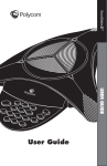
User’s Guide for the Polycom Mobile Responder October 2006 Edition 3725-23487-003/A VideoVoiceDataWeb Trademark Information Polycom®, the Polycom logo design, and SoundStation VTX 1000® are registered trademarks of Polycom, Inc. Mobile Responder™, People+Content™, PowerCam™, Pro-Motion™, and VSX™ are trademarks of Polycom, Inc. in the United States and various other countries. All other brand and product names are trademarks or registered trademarks of their respective companies. Patent Information The accompanying product is protected by one or more U.S. and foreign patents and/or pending patent applications held by Polycom, Inc. Disclaimer This software is provided 'as is' with no explicit or implied warranties in respect of its properties, including, but not limited to, correctness and fitness for purpose. Copyright Information © 2006 Polycom, Inc. All rights reserved. Polycom Inc. 4750 Willow Road Pleasanton, CA 94588-2708 USA No part of this document may be reproduced or transmitted in any form or by any means, electronic or mechanical, for any purpose, without the express written permission of Polycom, Inc. Under the law, reproducing includes translating into another language or format. As between the parties, Polycom, Inc. retains title to, and ownership of, all proprietary rights with respect to the software contained within its products. The software is protected by United States copyright laws and international treaty provision. Therefore, you must treat the software like any other copyrighted material (e.g. a book or sound recording). Every effort has been made to ensure that the information in this manual is accurate. Polycom, Inc. is not responsible for printing or clerical errors. Information in this document is subject to change without notice. Portions of the VSX software are copyright © 2001 by Dr. Brian Gladman. The following terms and disclaimer apply only to Dr. Gladman's AES encryption implementation: Copyright © 2001, Dr. Brian Gladman <[email protected]>, Worcester, UK. All rights reserved. License Terms The free distribution and use of this software in both source and binary form is allowed (with or without changes) provided that: 1. distributions of this source code include the above copyright notice, this list of conditions and the following disclaimer; 2. distributions in binary form include the above copyright notice, this list of conditions and the following disclaimer in the documentation and/or other associated materials; 3. the copyright holder's name is not used to endorse products built using this software without specific written permission. About this Guide This guide provides users of the Polycom® Mobile Responder™ system with information about how to set up the Mobile Responder, tips about using the system, and troubleshooting information. For additional information about the Polycom Mobile Responder, refer to these other documents: • Quick Setup for the Polycom Mobile Responder, which describes how to quickly identify the parts of the system, connect equipment to the connection panel, and power on the system. • Polycom Getting Started Guide for the VSX™ Series, which describes how to perform basic user tasks for the VSX video conferencing system, such as how to place video calls and use the remote control. • Polycom Administrator’s Guide for the VSX Series, which describes how to configure, customize, troubleshoot, and manage the VSX system. The Quick Setup for the Polycom Mobile Responder is shipped in hardcopy format with the Mobile Responder. The remaining documents are available on the documentation CDs that come with the Mobile Responder or at the Polycom web site, www.polycom.com/videodocumentation. For support or service, please contact your Polycom distributor or go to Polycom Support at www.polycom.com/support. iii User’s Guide for the Polycom Mobile Responder iv Contents 1 Introducing the Polycom Mobile Responder . . . . . . . . . . . . . . . . 1-1 System Components . . . . . . . . . . . . . . . . . . . . . . . . . . . . . . . . . . . . . . . . . . . . 1-2 Key Features . . . . . . . . . . . . . . . . . . . . . . . . . . . . . . . . . . . . . . . . . . . . . . . . . . . 1-3 Physical Attributes . . . . . . . . . . . . . . . . . . . . . . . . . . . . . . . . . . . . . . . . . . 1-3 Built-in Components . . . . . . . . . . . . . . . . . . . . . . . . . . . . . . . . . . . . . . . . 1-3 VSX 8000 System Technology . . . . . . . . . . . . . . . . . . . . . . . . . . . . . . . . . 1-4 2 Setting Up and Using the Polycom Mobile Responder . . . . . . . . . 2-1 Identifying System Parts . . . . . . . . . . . . . . . . . . . . . . . . . . . . . . . . . . . . . . . . . 2-2 Attaching the Remote Tether . . . . . . . . . . . . . . . . . . . . . . . . . . . . . . . . . . . . . 2-2 Connecting Equipment to the Connection Panel . . . . . . . . . . . . . . . . . . . . 2-4 Installing the Optional QBRI, PRI, or Serial Network Module . . . . . . . . . 2-6 Powering On the Mobile Responder . . . . . . . . . . . . . . . . . . . . . . . . . . . . . . . 2-8 Performing Video Conferencing Tasks . . . . . . . . . . . . . . . . . . . . . . . . . . . . 2-9 Tips on Using the Mobile Responder . . . . . . . . . . . . . . . . . . . . . . . . . . . . . . 2-9 Restoring System Settings . . . . . . . . . . . . . . . . . . . . . . . . . . . . . . . . . . . . . . 2-10 3 Troubleshooting . . . . . . . . . . . . . . . . . . . . . . . . . . . . . . . . . . . . 3-1 Solving Problems . . . . . . . . . . . . . . . . . . . . . . . . . . . . . . . . . . . . . . . . . . . . . . . 3-1 Power . . . . . . . . . . . . . . . . . . . . . . . . . . . . . . . . . . . . . . . . . . . . . . . . . . . . . 3-2 System Components . . . . . . . . . . . . . . . . . . . . . . . . . . . . . . . . . . . . . . . . . 3-3 Contacting Technical Support . . . . . . . . . . . . . . . . . . . . . . . . . . . . . . . . . . . . 3-5 Safety and Regulatory Notices . . . .Safety and Regulatory Notices-1 Index . . . . . . . . . . . . . . . . . . . . . . . . . . . . . . . . . . . . . Index-1 v User’s Guide for the Polycom Mobile Responder vi 1 Introducing the Polycom Mobile Responder The Polycom Mobile Responder is a complete video conferencing system packaged in a portable case. Based on Polycom’s VSX 8000 system, the Mobile Responder includes a built-in display, camera, microphone, speaker, and IP network interface. Because it is transportable and quick to set up, the Mobile Responder is ideal for anyone who wants to accomplish more while on the road or in the field. It is especially suited for rapid deployment and first-responder applications, such as homeland security, emergency management, military communications, and police and firefighters. The Mobile Responder complies with FAA carry-on luggage regulations. 1-1 User’s Guide for the Polycom Mobile Responder System Components These standard components come with the Polycom Mobile Responder: Name Component Description Polycom Mobile Responder The Polycom Mobile Responder is a transportable video conferencing system. The system offers built-in components, such as a display and camera, a connection panel that enables you to connect additional components, and the VSX 8000 user interface. VGA cable The VGA cable enables you to connect your Mobile Responder to an optional projector or an additional display. Power cables for North America, United Kingdom, and Europe The power cable connects power to the Mobile Responder. Use the cable that’s appropriate for your country. LAN cable The LAN cable connects the Mobile Responder to an IP network. S-video to RCA adapter The S-video to RCA adapter enables you to connect a composite video output device, such as some cameras and VCRs, to the Mobile Responder. VSX 8000 remote control The remote control is designed to make it easy to set up and operate the system — color-coded buttons correspond to system features. Remote tether The remote tether enables you to connect the remote control to the Mobile Responder so that you do not lose the remote control. Documentation • Quick Setup for the Polycom Mobile Responder 0OLYCOM -OBILE2ESPONDER© $OCUMENTATION,IBRARY 0OLYCOM 638©3ERIES $OCUMENTATION,IBRARY )NTERNET!CCESS2EQUIRED )NTERNET!CCESS2EQUIRED 1-2 • Polycom Mobile Responder documentation CD • Polycom VSX Series documentation CD Introducing the Polycom Mobile Responder You may also add optional components to your Mobile Responder. For example, you can add: • QBRI, PRI, or V.35 network interface modules • A laptop • A Polycom PowerCam™ camera, a PowerCam Plus camera, or a camera from a different manufacturer • A Polycom VSX microphone array or a SoundStation VTX 1000® conference phone • An additional display or a projector • A headset, handset, or headphones For information about purchasing optional equipment, please contact your Polycom distributor. Key Features Physical Attributes • Pull-out handle and inline (roller-blade style) wheels make it easy to pull the system along, just as you would roll a suitcase • Case size meets FAA regulations for carry-on luggage • Case is water and sand resistant • Friction hinges allow you to open the cover at the angle you find comfortable and also prevent the case from slamming shut • Interior accessory storage compartment enables you to bring along the remote control, LAN cable, and power cable • Remote tether enables you to connect the remote control to the system so you don’t have to be concerned about losing the remote control • 17” XGA-resolution LCD display • High-resolution, color camera with manual pan and tilt control • Hemi-cardioid microphone Built-in Components 1-3 User’s Guide for the Polycom Mobile Responder • Lid-mounted speaker • Convenient connection panel for connecting external devices, such as a VCR, laptop, or projector. VSX 8000 System Technology 1-4 • Easy-to-use VSX 8000 interface • Smooth Pro-Motion™ video delivers the highest image clarity • People+Content™ IP allows call participants to share content, such as spreadsheets and slides, during video calls • Built-in AES encryption • SIP (Session Initiation Protocol) support and QoS (Quality of Service) features 2 Setting Up and Using the Polycom Mobile Responder The Polycom Mobile Responder was specifically designed to be easy to set up. Many components, such as the camera and display, are built in, so they’re ready to use at a moment’s notice. If you want to add optional components, the connection panel is right inside the case so you can easily connect any cables you need. Once all your components are set up and you power on the Mobile Responder, you’re ready to use the system. This chapter describes how to set up the Mobile Responder, refers you to the documentation you need for more information about performing video conferencing functions, and provides helpful tips about using the system. 2-1 User’s Guide for the Polycom Mobile Responder Identifying System Parts The following illustration identifies the major parts of the Mobile Responder: 17” display Speaker Camera Power interlock switch (turns off power to lid when lid is closed) IR activity indicator LCD buttons: - Power - Up/Display Mode - Down - Select - Menu Side panel (Power button and connector) Connection panel IR receiver Accessory storage compartment Microphone Attaching the Remote Tether To operate the Mobile Responder, you need the remote control. If you are using the Mobile Responder in an environment where you could lose the remote, you can attach it to your Mobile Responder using the remote tether. Keep in mind that once you attach the remote control, you cannot remove it and attach it to a different location. 2-2 Setting Up and Using the Polycom Mobile Responder To attach the remote tether: 1. Peel the backing off one side of the remote tether, and stick it to the inside wall of the accessory storage compartment: By sticking the remote tether to the inside wall of the accessory storage compartment: — The remote tether remains out of the way of items stored inside the compartment. — You can close the Mobile Responder lid without damaging the display or any other components. 2. Peel the backing off the other side of the remote tether, and stick it to the side of the remote control: 2-3 User’s Guide for the Polycom Mobile Responder Connecting Equipment to the Connection Panel The Mobile Responder comes with built-in components, including the camera, microphone, display, and speaker. However, if you want to connect additional components to the system, you can do so very easily by using the connection panel. The following illustration shows some of the optional components you can connect to the connection panel. To purchase optional components, contact your Polycom distributor. 638 $XGLR,Q 0LF ,Q /LQH 2XW 9* $ 9* $ ,!. %.' ,!. 2-4 Setting Up and Using the Polycom Mobile Responder This connector... Enables you to... Mic In Connect to an external speaker system, headset, or handset. If you connect a device to the Mic In connector, the Mobile Responder’s internal microphone is deactivated. The internal microphone reactivates as soon as you disconnect the external device from this connector. Line Out Connect to a sound system or a headset. Because the internal speaker does not receive stereo audio, you must connect to an external sound system if you want to receive stereo audio. If you connect a sound system or headset to the Line Out connector, the Mobile Responder’s internal speaker is deactivated. The internal speaker reactivates as soon as you disconnect the external sound system or headset from this connector. VGA In Connect video from a computer or a laptop. For more information on how to connect a computer or laptop to the VGA In connector, refer to the Administrator’s Guide for the VSX Series, available on the VSX Series documentation CD that comes with the Mobile Responder. Audio In Connect audio from a computer or a laptop or from an external line-level source, such as audio from a VCR or DVD player. If you connect audio from a VCR or DVD player to the Audio In connector and you want to hear the audio from your VCR or DVD player, you must: • Set the Line Input (Red) and Line Input (White) settings to VCR (for more information about how to set these, refer to the audio settings table on page 2-11). • Press Camera on the VSX 8000 remote control and select Camera 1. For more information about the VSX 8000 Admin Settings, refer to the Administrator’s Guide for the VSX Series, available on the VSX Series documentation CD that comes with the Mobile Responder. VGA Out Connect to an external display, such as a different monitor or a projector. If you connect another monitor, this monitor displays the same video as the Mobile Responder’s built-in display. 2-5 User’s Guide for the Polycom Mobile Responder This connector... Camera 1 Control and Camera 1 In Enables you to... 1 1 Connect to an external camera, such as a Polycom PowerCam or PowerCam Plus. Alternatively, you can use the Camera 1 In connector to connect video from a VCR or DVD player. If you connect an external NTSC camera to the Camera 1 In connector, the Mobile Responder’s internal camera remains activated. However, if you connect an external PAL camera to the Camera 1 In connector, the internal camera is deactivated and the screen turns blue. For information on how to proceed once you have connected an external PAL camera, refer to page 3-3. LAN Connect to an IP network. Conference-Link Connect to an external digital microphone, such as a Polycom VSX microphone array or a SoundStation VTX 1000 conference phone. Because the internal microphone does not send stereo audio, you must connect an external digital microphone if you want to send stereo audio. If you connect a device to the Conference-Link connector, the Mobile Responder’s internal microphone remains activated. Installing the Optional QBRI, PRI, or Serial Network Module The Mobile Responder comes standard with an IP network interface. If you want to connect to another network interface, such as ISDN QBRI, ISDN PRI, or a serial network interface (V.35, RS-530, or RS-449), you must order the optional network module, install it, and then configure the new network interface. You can continue to use IP with any of the optional network modules; however, you cannot use more than one optional network module at the same time. For example, you cannot use QBRI and V.35 at the same time. To install the optional QBRI, PRI, or serial network module: 1. Make sure that the power is off. 2-6 Setting Up and Using the Polycom Mobile Responder 2. Using a slotted screwdriver, open the back panel of the Mobile Responder by rotating the lock 180 degrees: 3. Remove the back panel. 4. Using a Phillips screwdriver, unscrew the plate inside, and remove it as well. 5. Slide in the network module all the way to the back: 6. Tighten the screws on each side of the network module. 7. If you plan to use to the optional network interface right away, attach the network cable to the module. If you do not plan to use the optional network interface for some time, you may want to replace the back panel to maintain water and sand resistance. 8. Configure the VSX 8000 for use with the new network interface. For example, for ISDN QBRI, you must enable ISDN H.320, enter the number assigned to each channel, and so forth. For information how to configure your new network interface, refer to the Administrator’s Guide for the VSX Series, which is available on the VSX Series documentation CD that comes with the Mobile Responder or at www.polycom.com/videodocumentation. 2-7 User’s Guide for the Polycom Mobile Responder Powering On the Mobile Responder After you have connected any additional equipment to the Mobile Responder, you can connect the power cable and then power on the Mobile Responder. The power consumption for the Mobile Responder is listed in the following table: During this time... The power consumption is... Startup 0.5 amp to 1 amp @ 100 - 240 VAC Running idle 1.2 amps @ 100 - 240 VAC LAN call 1.2 amps @ 100 - 240 VAC To connect the power cable: 1. Open the side panel of the Mobile Responder by pressing down on the latch. Inside the side panel is the power connector and Power button. 2. Make sure you have the appropriate power cable for your country, and connect one end of the cable to the power connector inside the side panel. 3. Connect the other end of the power cable to a wall outlet. Note The Mobile Responder can accept AC voltages between 98 and 250 VAC. To power on the Mobile Responder: 1. Press the Power button located inside the side panel to the ON position. 2. Wait one to two minutes for the system to completely power on. When the system is powered on, the VSX 8000 home screen appears on the display. 2-8 Setting Up and Using the Polycom Mobile Responder Performing Video Conferencing Tasks Because the Mobile Responder is based on Polycom’s VSX 8000 video conferencing system, you can use your Mobile Responder to perform virtually all of the video conferencing tasks that you can perform with a VSX 8000. For example, you can place and end video calls, share data, customize the look and behavior of the system for your particular needs, and so on. For complete information about how to use the VSX 8000 to place calls and perform other video conferencing tasks, refer to the Administrator’s Guide for the VSX Series and the Getting Started Guide for the VSX Series. Both of these documents are available on the VSX Series documentation CD that comes with the Mobile Responder or at www.polycom.com/videodocumentation. Tips on Using the Mobile Responder • The Mobile Responder weighs 39 pounds (18 kilograms). You should get help lifting it if you cannot carry this much weight. • Although the Mobile Responder is built to withstand the rigors of travel, you should handle it as you would handle a laptop. For example, if you are traveling by air, be sure to bring the Mobile Responder with you as a carry-on, and place it carefully in the overhead storage compartment. • Operate the Mobile Responder in an environment within the range of 15% to 90% relative humidity. • Store the items you use with your system, such as the remote control and power cable, inside the accessory storage compartment. • To avoid damaging the display, close the accessory storage compartment and remove any cables connected to the connection panel before closing the case. • You can manually pan and tilt the camera; however, it has a fixed focus. • To bring up the pull-out handle on the Mobile Responder, push the latch to the right. You can then conveniently pull the system along on its two wheels, just as you would roll a suitcase. • For extra security, add a padlock to the system using the holes on each side of the handle. • Typically, you should not need to adjust the display. However, if you do need to make adjustments, you can use the LCD buttons to the right of the display (for an illustration of where these buttons are located, refer to Identifying System Parts on page 2-2). 2-9 User’s Guide for the Polycom Mobile Responder Restoring System Settings If you reset the VSX 8000 to the factory defaults and delete the system settings, follow these steps to restore the system settings for the Mobile Responder: 1. Press and hold down the button on the remote control while powering on the Mobile Responder. Hold the button until the Polycom logo appears on the screen. 2. Use the remote control to select a language, and then follow the remaining screens in the setup wizard. 3. Set these camera settings: On this VSX 8000 screen... Set this field... To this setting... System > Admin Settings > Cameras Primary Camera 2 System > Admin Settings > Cameras (page 2) Camera 1 Source S-Video Camera 2 Source Composite People 4. Set these audio settings: On this VSX 8000 screen... System > Admin Settings > Audio (page 2) 2 - 10 Set this field... To this setting... Input Type Microphone Level 10 Echo canceller Enabled Enable Phantom Power Disabled Setting Up and Using the Polycom Mobile Responder On this VSX 8000 screen... System > Admin Settings > Audio (page 4) Set this field... To this setting... Line Input (Red) Visual Concert (if you connect a computer or laptop to the Audio In connector) or VCR (if you connect a VCR or DVD player to the Audio In connector) Level 5 Line Input (White) Visual Concert (if you connect a computer or laptop to the Audio In connector) or VCR (if you connect a VCR or DVD player to the Audio In connector) Level 5 System > Admin Settings > Audio (page 5) Master Audio Volume 25 (or higher) 5. Set these monitor settings: On this VSX 8000 screen... Set this field... To this setting... System > Admin Settings > Monitors > Monitors Monitor 1 VGA Monitor 1 Aspect Ratio 4:3 System > Admin Settings > Monitors > Monitors (page 3) Zoom Video to Fit Screen Disabled Dual Monitor Emulation Disabled System > Admin Settings > Monitors > Graphics VGA VGA Resolution 1024 x 768 60Hz 2 - 11 User’s Guide for the Polycom Mobile Responder 2 - 12 3 Troubleshooting This chapter presents problems, likely causes, and corrective actions for the Mobile Responder. Problems are organized by category to help you troubleshoot them quickly. You can find additional troubleshooting information in the Administrator’s Guide for the VSX Series, which is available on the VSX Series documentation CD that comes with the Mobile Responder or at www.polycom.com/videodocumentation. This document can help you identify and correct issues associated with the VSX 8000, such as problems accessing system screens or problems making video calls. If you have referred to the documentation and you still are unable to resolve your issue, contact Polycom Technical Support. The last section of this chapter tells you how to do so. Solving Problems To find and resolve your problem, look under one of these sections: • Power • System Components 3-1 User’s Guide for the Polycom Mobile Responder Power Symptom Problem Corrective Action The system does not start or respond in any way. The Power button is off. 1. Press the Power button located inside the side panel to the on position. 2. Wait one to two minutes for the system to completely power on. The power cable is not connected. Make sure the power cable is connected to a power outlet, and that the power cable is seated securely both in the outlet and in the Mobile Responder. The power outlet is not active, or the system’s power cable is not operating properly. Check the power outlet by unplugging the system and plugging in a lamp, radio, or other small appliance. If it does not operate, the outlet is not active — connect the system to a different outlet. If the outlet is active, the problem may be in the Mobile Responder’s power cable. In this case, call Polycom Technical Support. The screen is blank. 3-2 The power interlock switch is pushed down. Make sure that the power interlock switch, which turns off power to the lid, is up (refer to Identifying System Parts on page 2-2 for an illustration showing where the power interlock switch is located). The system is in standby mode. Pick up the remote control to activate the system. The power for the display is off. Press the LCD Power button to turn the display on (refer to Identifying System Parts on page 2-2 for an illustration showing where the LCD Power button is located). The wrong display mode is selected. Press the LCD Up/Display Mode button until you set the display mode to RGB (refer to Identifying System Parts on page 2-2 for an illustration showing where the LCD Up/Display Mode button is located). Troubleshooting System Components Symptom Problem Corrective Action The screen is blue. You connected an external PAL camera to the Camera 1 In 1 connector, which deactivates the internal camera. Do one of the following: • If you plan to use an external PAL camera all of the time, go to System > Admin Settings > Cameras and set the Primary Camera setting to 1. • If you want to view video from the external PAL camera, but do not plan on using this camera all of the time, press Camera on the remote control and select the appropriate camera source. Note that when you disconnect the external PAL camera, the internal camera reactivates. To view video from the internal camera, press Camera on the remote control and select the appropriate camera source. No video from the external camera. The video is not centered on the LCD screen. Camera inputs and outputs are not connected correctly. Refer to Connecting Equipment to the Connection Panel on page 2-4 for information on how to connect an external camera correctly. You connected a composite video output device using the S-video to RCA adapter, but you did not set the video format to Composite. Go to System > Admin Settings > Cameras (page 2) and set the Video Format setting to Composite. The screen is not calibrated correctly. The Mobile Responder comes with an auto-calibration feature. However, in order for this feature to properly center the video on the screen, you must be viewing full-screen video. To view full-screen video and properly calibrate the screen: 1. Go to System > Admin Settings > Monitors > Monitors and enable Zoom video to fit screen OR set the Monitor 1 aspect ratio to 4:3. 2. Press Near on the remote control to view full-screen video. 3. Press the Select LCD button to auto-calibrate the screen (refer to Identifying System Parts on page 2-2 for an illustration showing where the Select button is located). Cannot receive or send stereo audio. Stereo audio is not available with the built-in microphone and speakers. To receive stereo audio, connect external speakers or speakers on a headset to the Line Out connector. To send stereo audio, connect an external digital microphone, such as a Polycom microphone or a SoundStation VTX 1000 conference phone, to the Conference-Link connector. 3-3 User’s Guide for the Polycom Mobile Responder Symptom Problem Corrective Action The people at the far site cannot hear you or you cannot hear them. The people at your site or at the far site are too far from the microphone. Move closer to the microphone or turn up the volume using the remote control. Also, if you are using an external microphone, check that the microphone is correctly connected. The microphone at your site or at the far site is muted. Make sure all microphones are not muted. To unmute a microphone, you can press Mute on the remote control or, with some external microphones, you can press Mute on the microphone itself. Your system’s microphone does not work. Contact your Polycom reseller. Audio inputs and outputs are not connected correctly. Refer to Connecting Equipment to the Connection Panel on page 2-4 for information on how to connect microphones and other audio equipment correctly. Too many line errors or other audio issues. Refer to the Administrator’s Guide for the VSX Series for more audio troubleshooting information. You connected a VCR or DVD player, but you did not specify the appropriate VSX 8000 settings. If you connect audio from a VCR or DVD player to the Audio In connector and you want to hear the audio from your VCR or DVD player, you must: No audio from the VCR or DVD player. • Set the Line Input (Red) and Line Input (White) settings to VCR (refer to the audio settings on page 2-11 for more information about how to set these). • Press Camera on the remote control and select Camera 1. Refer to the Administrator’s Guide for the VSX Series for more information about the VSX 8000 Admin Settings. No audio from a PC microphone or from a PC headset with a microphone. The Mobile Responder does not support condenser (electret) microphones that require a bias voltage. Switch to a microphone supported by the Mobile Responder, including: • Any dynamic microphone. • Most professional condenser microphones that require phantom power. • Most professional condenser microphones that operate on an external battery. The system does not respond to the VSX remote control. 3-4 The batteries in the remote control are low, dead, or missing. Install three AAA batteries in the remote control. The batteries are installed incorrectly in the remote control. Insert the batteries in the correct +/- position. The IR receiver is not receiving signals from the remote control. Make sure you are pointing the remote control at the IR receiver, which is located below the speaker on the Mobile Responder (refer to Identifying System Parts on page 2-2 for an illustration showing where the IR receiver is located). Troubleshooting Contacting Technical Support To contact Polycom Technical Support, go to www.polycom.com/support. You can enter information about your system and ask a question or describe your problem. When contacting Technical Support, be sure you know the serial number of your system. The serial number is located on the inside of the side panel cover. 3-5 User’s Guide for the Polycom Mobile Responder 3-6 Safety and Regulatory Notices Important Safeguards Read and understand the following instructions before using the system: • Close supervision is necessary when the system is used by or near children. Do not leave unattended while in use. • Only use electrical extension cords with a current rating at least equal to that of the system. • Always disconnect the system from power before cleaning and servicing and when not in use. • Do not spray liquids directly onto the system when cleaning. Always apply the liquid first to a static free cloth. • Do not immerse the system in any liquid or place any liquids on it. • Do not disassemble this system. To reduce the risk of shock and to maintain the warranty on the system, a qualified technician must perform service or repair work. • Connect this appliance to a grounded outlet. • Only connect the system to surge protected power outlets. • Keep ventilation openings free of any obstructions. • If the system or any accessories are installed in an enclosed space, ensure that the air temperature in the enclosure does not exceed 40ºC (104ºF). You may need to provide forced cooling to keep the equipment within its operating temperature range. SAVE THESE INSTRUCTIONS. Safety and Regulatory Notices - 1 User’s Guide for the Polycom Mobile Responder License Restrictions THE SOFTWARE PROGRAMS CONTAINED OR DESCRIBED HEREIN ARE CONFIDENTIAL INFORMATION AND PROPRIETARY PRODUCTS OF POLYCOM, INC. OR ITS LICENSORS. Buyer shall not sublicense or otherwise distribute any of the Subject Programs except to End Users and/or resellers who have entered into a Sublicense Agreement. For purposes of this Agreement a “Sublicense Agreement” shall mean a written license agreement between the Buyer and its purchaser, or, in the case of any sale by Buyer to a reseller, between such reseller and the End User, that is either 1) signed by the End User or 2) included with the Documentation, in such a manner that the End User reasonably indicates its acceptance of the Sublicense Agreement by turning on and using the Computer Equipment. Polycom, Inc. shall include so-called “break the seal software licenses” with the Documentation, and Buyer shall not remove or alter any such Sublicense Agreements or any notifications or warning stickers relating thereto. Buyer shall not waive, amend, or otherwise modify any Sublicense Agreement without Polycom’s prior consent. Title to all Subject Programs shall at all times remain and vest solely with Polycom, Inc. and its licensors. Buyer acknowledges Polycom’s claim that the Subject Programs are its trade secret and confidential property, and shall treat them as such. Buyer will not attempt to disassemble, decompile, reverse-engineer or otherwise endeavor to discover or disclose the methods and concepts embodied in the Subject Programs. Except as expressly allowed under this Agreement, the Buyer shall not copy, modify, transcribe, store, translate, sell, lease, or otherwise transfer or distribute any of the Subject Programs in whole or in part, without prior authorization, in writing, from Polycom, Inc. Buyer shall not remove or destroy any copyright, patent, trademark or other proprietary mark or notice on Computer Equipment, and shall reproduce any such marks on any copies of Subject Programs that it makes hereunder. You shall not, and shall not allow, any third party to 1) decompile, disassemble, or otherwise reverse-engineer or attempt to reconstruct or discover any source code or underlying ideas or algorithms of the software by any means whatsoever or 2) remove any product. Warranty Information LIMITED WARRANTY. Polycom warrants to the end user (“Customer”) that the product will be free from defects in workmanship and materials, under normal use and service, for one year, or such longer period as Polycom may announce publicly from time to time for particular products, from the date of purchase from Polycom or its authorized reseller. Polycom’s sole obligation under this express warranty shall be, at Polycom’s option and expense, to repair the defective product or part, deliver to Customer an equivalent product or part to replace the defective item, or if neither of the two foregoing options is reasonably available, Polycom may, in its sole discretion, refund to Customer the purchase price paid for the defective product. All products that are replaced will become the property of Polycom. Replacement products or parts may be new or reconditioned. Polycom warrants any replaced or repaired product or part for ninety (90) days from shipment, or the remainder of the initial warranty period, whichever is longer. Products returned to Polycom must be sent prepaid and packaged appropriately for safe shipment, and it is recommended that they be insured or sent by a method that provides for tracking of the package. Responsibility for loss or damage does not transfer to Polycom until the returned item is received by Polycom. The repaired or replaced item will be shipped to Customer, at Polycom's expense, not later than thirty (30) days after Polycom receives the defective product, and Polycom will retain risk of loss or damage until the item is delivered to Customer. Safety and Regulatory Notices - 2 Safety and Regulatory Notices Warranty Information EXCLUSIONS. POLYCOM WILL NOT BE LIABLE UNDER THIS LIMITED WARRANTY IF ITS TESTING AND EXAMINATION DISCLOSE THAT THE ALLEGED DEFECT OR MALFUNCTION IN THE PRODUCT DOES NOT EXIST OR RESULTS FROM: • FAILURE TO FOLLOW POLYCOM'S INSTALLATION, OPERATION, OR MAINTENANCE INSTRUCTIONS. • UNAUTHORIZED PRODUCT MODIFICATION OR ALTERATION. • UNAUTHORIZED USE OF COMMON CARRIER COMMUNICATION SERVICES ACCESSED THROUGH THE PRODUCT. • ABUSE, MISUSE, NEGLIGENT ACTS OR OMISSIONS OF CUSTOMER AND PERSONS UNDER CUSTOMER'S CONTROL; OR • ACTS OF THIRD PARTIES, ACTS OF GOD, ACCIDENT, FIRE, LIGHTING, POWER SURGES OR OUTAGES, OR OTHER HAZARDS. WARRANTY EXCLUSIVE. IF A POLYCOM PRODUCT DOES NOT OPERATE AS WARRANTED ABOVE, CUSTOMER'S SOLE REMEDY FOR BREACH OF THAT WARRANTY SHALL BE REPAIR, REPLACEMENT, OR REFUND OF THE PURCHASE PRICE PAID, AT POLYCOM'S OPTION. TO THE FULL EXTENT ALLOWED BY LAW, THE FOREGOING WARRANTIES AND REMEDIES ARE EXCLUSIVE AND ARE IN LIEU OF ALL OTHER WARRANTIES, TERMS, OR CONDITIONS, EXPRESS OR IMPLIED, EITHER IN FACT OR BY OPERATION OF LAW, STATUTORY OR OTHERWISE, INCLUDING WARRANTIES, TERMS, OR CONDITIONS OF MERCHANTABILITY, FITNESS FOR A PARTICULAR PURPOSE, SATISFACTORY QUALITY, CORRESPONDENCE WITH DESCRIPTION, AND NON-INFRINGEMENT, ALL OF WHICH ARE EXPRESSLY DISCLAIMED. POLYCOM NEITHER ASSUMES NOR AUTHORIZES ANY OTHER PERSON TO ASSUME FOR IT ANY OTHER LIABILITY IN CONNECTION WITH THE SALE, INSTALLATION, MAINTENANCE OR USE OF ITS PRODUCTS. SUPPORT & SERVICE AGREEMENTS. If you purchased your product from a Polycom Authorized Reseller, contact the Authorized Reseller for information about support and service agreements applicable to your product. For information on Polycom service, go to the Polycom web site www.polycom.com, products and services menu, or call 1-800-765-9266, outside the US call 1-408-526-9000, or your local Polycom Office, as listed on the Polycom Web site. LIMITATION OF LIABILITY. TO THE FULL EXTENT ALLOWED BY LAW, POLYCOM EXCLUDES FOR ITSELF AND ITS SUPPLIERS ANY LIABILITY, WHETHER BASED IN CONTRACT OR TORT (INCLUDING NEGLIGENCE), FOR INCIDENTAL, CONSEQUENTIAL, INDIRECT, SPECIAL, OR PUNITIVE DAMAGES OF ANY KIND, OR FOR LOSS OF REVENUE OR PROFITS, LOSS OF BUSINESS, LOSS OF INFORMATION OR DATA, OR OTHER FINANCIAL LOSS ARISING OUT OF OR IN CONNECTION WITH THE SALE, INSTALLATION, MAINTENANCE, USE, PERFORMANCE, FAILURE, OR INTERRUPTION OF ITS PRODUCTS, EVEN IF POLYCOM OR ITS AUTHORIZED RESELLER HAS BEEN ADVISED OF THE POSSIBILITY OF SUCH DAMAGES, AND LIMITS ITS LIABILITY TO REPAIR, REPLACEMENT, OR REFUND OF THE PURCHASE PRICE PAID, AT POLYCOM'S OPTION. THIS DISCLAIMER OF LIABILITY FOR DAMAGES WILL NOT BE AFFECTED IF ANY REMEDY PROVIDED HEREIN SHALL FAIL OF ITS ESSENTIAL PURPOSE. DISCLAIMER. Some countries, states, or provinces do not allow the exclusion or limitation of implied warranties or the limitation of incidental or consequential damages for certain products supplied to consumers, or the limitation of liability for personal injury, so the above limitations and exclusions may be limited in their application to you. When the implied warranties are not allowed to be excluded in their entirety, they will be limited to the duration of the applicable written warranty. This warranty gives you specific legal rights which may vary depending on local law. GOVERNING LAW. This Limited Warranty and Limitation of Liability shall be governed by the laws of the State of California, U.S.A., and by the laws of the United States, excluding their conflicts of laws principles. The United Nations Convention on Contracts for the International Sale of Goods is hereby excluded in its entirety from application to this Limited Warranty and Limitation of Liability. Safety and Regulatory Notices - 3 User’s Guide for the Polycom Mobile Responder Regulatory Notices Warning This is a Class A product. In a domestic environment, this product may cause radio interference in which case the user may be required to take adequate measures. USA and Canadian Regulatory Notices FCC Notice Class A Digital Device or Peripheral This equipment has been tested and found to comply with the limits for a Class A digital device, pursuant to Part 15 of the FCC Rules. These limits are designed to provide reasonable protection against harmful interference when the equipment is operated in a commercial environment. This equipment generates, uses, and can radiate radio frequency energy and, if not installed and used in accordance with the instruction manual, may cause harmful interference to radio communications. Operation of this equipment in a residential area is likely to cause harmful interference in which case the user will be required to correct the interference at his own expense. In accordance with Part 15 of the FCC rules, the user is cautioned that any changes or modifications not expressly approved by Polycom Inc. could void the user's authority to operate this equipment. The socket outlet to which this apparatus is connected must be installed near the equipment and must always be readily accessible. Part 15 FCC Rules This device complies with part 15 of the FCC rules. Operation is subject to the following two conditions: 1) This device may not cause harmful interference, and 2) this device must accept any interference received, including interference that may cause undesired operation. Part 68 FCC Rules This equipment complies with part 68 of the FCC rules and the rules adopted by the ACTA. On the Network Interface Module of this equipment is a label that contains, among other information, a product identifier in the format US:AAAEQ#TXXX. If requested, this number must be provided to the telephone company. This equipment may not be used on a coin service or party line. If you experience trouble with your system, disconnect it from the telephone line to determine if the registered equipment is malfunctioning. For repair or warranty information, please contact Polycom Inc. at 1-888-248-4143 or 4750 Willow Road, Pleasanton, CA 94588-2708, USA. Contact information may also be found at http://www.polycom.com. If the system is causing harm to the network, the telephone company may request that you disconnect it until the problem is corrected. If your Mobile Responder causes harm to the telephone network, the telephone company will notify you in advance that temporary discontinuance of service may be required. However, if advance notice is not practical, you will be notified as soon as possible. You will be advised of your right to file a complaint with the FCC if you believe it is necessary. Your telephone company may make changes in its facilities, equipment, operations, or procedures that could affect the operation of your equipment. If they do, you will be given advance notice so that you may make any changes necessary to maintain uninterrupted service. The REN is useful to determine the quantity of devices that may be connected to the telephone line. Excessive RENs on the telephone line may result in the devices not ringing in response to an incoming call. In most, but not all areas, the sum of RENs of all devices that may be connected to a line, is determined by the total RENs, contact the local telephone company. Safety and Regulatory Notices - 4 Safety and Regulatory Notices Regulatory Notices The system can accept AC voltages between 98 and 250 VAC, 7A 50-60 Hz. FCC compliant telephone cords and modular plugs are provided with this equipment. This equipment is designed to be connected to the telephone network or premises’ wiring using a compatible modular jack, which is Part 68 compliant. See installation instructions for details. WHEN PROGRAMMING EMERGENCY NUMBERS AND/OR MAKING TEST CALLS TO EMERGENCY NUMBERS: 1) Remain on the line and briefly explain to the dispatcher the reason for the call. 2) Perform such activities in the off-peak hours, such as early morning or late evening. Industry Canada (IC) This Class [A] digital apparatus complies with Canadian ICES-003. Cet appareil numerique de la Classe [A] est conforme à la norme NMB-003 du Canada. The Industry Canada label identifies certified equipment. This certification means that the equipment meets telecommunications network protective, operational and safety requirements as prescribed in the appropriate Terminal Equipment Technical Requirements document(s). The Department does not guarantee the equipment will operate to the user's satisfaction. Before installing this equipment, users should ensure that it is permissible to be connected to the facilities of the local telecommunications company. The equipment must also be installed using an acceptable method of connection. The customer should be aware that compliance with the above conditions may not prevent degradation of service in some situations. Repairs to certified equipment should be coordinated by a representative designated by the supplier. Any repairs or alterations made by the user to this equipment, or equipment malfunctions, may give the telecommunications company cause to request the user to disconnect the equipment. Users should ensure for their own protection that the electrical ground connections of the power utility, telephone lines and internal metallic water pipe system, if present, are connected together. This precaution may be particularly important in rural areas. Caution: Users should not attempt to make such connections themselves, but should contact the appropriate electric inspection authority, or electrician, as appropriate. The Ringer Equivalence Number (REN) assigned to each relevant terminal device provides an indication of the maximum number of terminals allowed to be connected to a telephone interface. The termination on an interface may consist of any combination of devices subject only to the requirement that the sum of the RENs of all the devices does not exceed 5. The REN of this equipment is either marked on the unit or included in the new style USA FCC registration number. In the case that the REN is included in the FCC number, the user should use the following key to determine the value: The FCC number is formatted as US:AAAEQ#TXXX. # is the Ringer Equivalence Number without a decimal point (e.g. REN of 1.0 will be shown as 10, REN of 0.3 will be shown as 03). In the case of a Z ringer, ZZ shall appear. In the case of approved equipment without a network interface or equipment not to be connected to circuits with analog ringing supplied, NA shall appear. EEA Regulatory Notices CE Mark R & TTE Directive This Mobile Responder has been marked with the CE mark. This mark indicates compliance with EEC Directives 89/336/EEC, 73/23/EEC 1999/5/EC. A full copy of the Declaration of Conformity can be obtained from Polycom Ltd., 270 Bath Road, Slough UK SL1 4DX. Safety and Regulatory Notices - 5 User’s Guide for the Polycom Mobile Responder Regulatory Notices Declaration of Conformity: Hereby, Polycom Ltd. declares that this Mobile Responder is in compliance with the essential requirements and other relevant provisions of Directive 1999/5/EC. Konformitetserklæring: Hermed erklærer Polycom Ltd., at indestående Mobile Responder er i overensstemmelse med de grundlæggende krav og de relevante punkter i direktiv 1999/5/EF. Konformitätserklärung: Hiermit erklärt Polycom Ltd., dass der Mobile Responder die grundlegenden Anforderungen und sonstige maßgebliche Bestimmungen der Richtlinie 1999/5/EG erfüllt. Vaatimustenmukaisuusvakuutus: Polycom Ltd. vakuuttaa täten, että Mobile Responder on direktiivin 1999/5/EC keskeisten vaatimusten ja sen muiden tätä koskevien säännösten mukainen. Déclaration de conformité: Par la présente, Polycom Ltd. déclare que ce Mobile Responder est conforme aux conditions essentielles et à toute autre modalité pertinente de la Directive 1999/5/CE. Dichiarazione di conformità: Con la presente Polycom Ltd. dichiara che il Mobile Responder soddisfa i requisiti essenziali e le altre disposizioni pertinenti della direttiva 1999/5/CE. Verklaring van overeenstemming: Hierbij verklaart Polycom Ltd. dat diens Mobile Responder voldoet aan de basisvereisten en andere relevante voorwaarden van EG-richtlijn 1999/5/EG. Declaração de Conformidade: Através da presente, a Polycom Ltd. declara que este Mobile Responder se encontra em conformidade com os requisitos essenciais e outras disposições relevantes da Directiva 1999/5/CE. Declaración de conformidad: Por la presente declaración, Polycom Ltd. declara que este Mobile Responder cumple los requisitos esenciales y otras cláusulas importantes de la directiva 1999/5/CE. Överensstämmelseförklaring: Polycom Ltd. förklarar härmed att denna Mobile Responder överensstämmer med de väsentliga kraven och övriga relevanta stadganden i direktiv 1999/5/EG. CE Mark LVD and EMC Directive This system has been marked with the CE mark. This mark indicates compliance with EEC Directives 89/336/EEC and 73/23/EEC. A full copy of the Declaration of Conformity can be obtained from Polycom Ltd., 270 Bath Road, Slough UK SL1 4DX, UK. Safety and Regulatory Notices - 6 Safety and Regulatory Notices Regulatory Notices Special Safety Instructions Follow existing safety instructions and observe all safeguards as directed. Installation Instructions Installation must be performed in accordance with all relevant national wiring rules. Plug Acts as Disconnect Device The socket outlet to which this apparatus is connected must be installed near the equipment and must always be readily accessible. Safety and Regulatory Notices - 7 User’s Guide for the Polycom Mobile Responder Safety and Regulatory Notices - 8 Index A accessory storage compartment attaching remote tether to 2-3 location of 2-2 tips 2-9 adapter, S-video to RCA 1-2, 3-3 Audio In connector 2-5 audio, troubleshooting 3-3, 3-4 B back panel, removing 2-7 C cable LAN 1-2 power 1-2 VGA 1-2 camera connecting 2-6 location of 2-2 troubleshooting 3-3 components built-in 1-3 optional 1-3 standard 1-2 composite video 1-2, 3-3 computer, connecting 2-5 Conference-Link connector 2-6 connection panel connecting equipment to 2-4 illustration of 2-5 location of 2-2 connector Audio In 2-5 Conference-Link 2-6 LAN 2-6 Line Out 2-5 Mic In 2-5 VGA In 2-5 VGA Out 2-5 D display adjusting 2-9 connecting 2-5 location of 2-2 documentation, list of 1-2 DVD player, troubleshooting 3-4 E encryption 1-4 equipment connecting to connection panel 2-4 optional 1-3 standard 1-2 H handset, connecting 2-5 headset, connecting 2-5 humidity rating 2-9 I IR receiver location of 2-2 not receiving signals 3-4 ISDN, installing network module 2-6 L LAN cable 1-2 LAN connector 2-6 laptop, connecting 2-5 LCD buttons adjusting display 2-9 location of 2-2 Line Out connector 2-5 M Mic In connector 2-5 Index – 1 User’s Guide for the Polycom Mobile Responder microphone connecting 2-6 location of 2-2 troubleshooting 3-4 Mobile Responder attaching remote tether to 2-3 built-in components 1-3 connecting equipment to 2-4 contacting technical support 3-5 identifying system parts 2-2 introduction 1-1 key features 1-3 physical attributes 1-3 powering on 2-8 restoring system settings 2-10 setting up 2-1 system components 1-2 tips on using 2-9 troubleshooting 3-1 weight of 2-9 monitor, connecting 2-5 N network connecting to IP 2-6 installing network module 2-6 O optional equipment 1-3 P padlock 2-9 parts, of system 2-2 patch panel, See connection panel People+Content 1-4 power accepted voltages 2-8 connecting power cable 2-8 powering on Mobile Responder 2-8 troubleshooting 3-2 power cable connecting 2-8 illustration 1-2 PRI, installing network module 2-6 projector, connecting 2-5 Pro-Motion 1-4 Q QBRI, installing network module 2-6 QoS (Quality of Service) 1-4 Index – 2 R regulatory notices Safety and Regulatory Notices-1 remote control attaching tether to 2-3 description of 1-2 troubleshooting 3-4 remote tether attaching 2-2 description of 1-2 restoring system settings 2-10 RS-449, installing network module 2-6 RS-530, installing network module 2-6 S safety notices Safety and Regulatory Notices-1 serial network interface, installing network module 2-6 settings, restoring 2-10 SIP (Session Initiation Protocol) 1-4 software, list of 1-2 sound system, connecting 2-5 speaker connecting 2-5 location of 2-2 standard equipment 1-2 storage compartment, See accessory storage compartment support, contacting 3-5 S-video to RCA adapter 1-2 system parts, identifying 2-2 system settings, restoring 2-10 T technical support, contacting 3-5 tether, remote attaching 2-2 description of 1-2 troubleshooting power 3-2 system components 3-3 V V.35, installing network module 2-6 VCR, troubleshooting 3-4 VGA cable 1-2 VGA In connector 2-5 VGA Out connector 2-5 video conferencing, performing tasks 2-9 Index video, troubleshooting 3-3 VSX included features 1-4 performing video conferencing tasks 2-9 remote control 1-2 restoring system settings 2-10 Index - 3