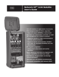
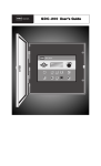
1
Network VPE Satellite User’s Guide •16 to 64 stations in eight-station increments •Field programmable for future upgrades • Does not require EPROM(s) replacement •Operates as a stand-alone controller or under the management of a central computer. • Supports wireline or radio communications with the central computer • Supports hybrid communication (wireline and radio) for increased flexibility and cost effectiveness •16 irrigation programs: • Independent stand-alone and central operation •Multi-Manual, Program Start and Syringe manual operations •Operates up to 16 stations simultaneously Index Radio Specifications - - - - - - - - - - - - - - - - - - - - - - - - - - - - - - 3 Fuse and Circuit Breaker Specifications - - - - - - - - - - - - - - - 3 Satellite Controller Specifications - - - - - - - - - - - - - - - - - - - - 3 Introduction - - - - - - - - - - - - - - - - - - - - - - - - - - - - - - - - - - - - 4 Modes of Operation - - - - - - - - - - - - - - - - - - - - - - - - - - - - - - - 4 General Editing - - - - - - - - - - - - - - - - - - - - - - - - - - - - - - - - - - 4 Menu Symbols - - - - - - - - - - - - - - - - - - - - - - - - - - - - - - - - - - - 4 Timing Mechanism Components - - - - - - - - - - - - - - - - - - - - - - 5 Distribution Board Components - - - - - - - - - - - - - - - - - - - - - - 6 Output Board Components - - - - - - - - - - - - - - - - - - - - - - - - - 6 Pump / Common Board Components - - - - - - - - - - - - - - - - - - 7 Communication Board Components - - - - - - - - - - - - - - - - - - - 7 Power-Up Diagnostics - - - - - - - - - - - - - - - - - - - - - - - - - - - - - 8 Home Key - - - - - - - - - - - - - - - - - - - - - - - - - - - - - - - - - - - - - - 8 Start Key - - - - - - - - - - - - - - - - - - - - - - - - - - - - - - - - - - - - - - 9 Pause / Resume Key - - - - - - - - - - - - - - - - - - - - - - - - - - - - 10–11 Stop Key - - - - - - - - - - - - - - - - - - - - - - - - - - - - - - - - - - - - - - Satellite Settings - - - - - - - - - - - - - - - - - - - - - - - - - - - - - - 12–13 Station Settings - - - - - - - - - - - - - - - - - - - - - - - - - - - - - - - - Scheduled Watering - - - - - - - - - - - - - - - - - - - - - - - - - - - 11 14 15–17 • Irrigation Program - - - - - - - - - - - - - - - - - - - - - - - - - - - - 15 • Station Based Flow Management - - - - - - - - - - - - - - - - - 17 Manual Watering - - - - - - - - - - - - - - - - - - - - - - - - - - - - - - 18–19 • Multi-Manual - - - - - - - - - - - - - - - - - - - - - - - - - - - - - - - - 18 • Manual Syringe - - - - - - - - - - - - - - - - - - - - - - - - - - - - - - 19 • Manual Program - - - - - - - - - - - - - - - - - - - - - - - - - - - - - 19 % (Percent) Adjust - - - - - - - - - - - - - - - - - - - - - - - - - - - - - - 20 Diagnostics - - - - - - - - - - - - - - - - - - - - - - - - - - - - - - - - - - - - - 21 Trouble Shooting Guide - - - - - - - - - - - - - - - - - - - - - - - - - 22–23 Lithium Battery Replacement - - - - - - - - - - - - - - - - - Back Cover Electromagnetic Compatibility - - - - - - - - - - - - - - - - Back Cover 2 Radio Specifications Equipment Type – Data radio, MAXON, model SD-125 U2 Frequency Band – UHF RF Output Power – 2.0 watt Current Consumption: Standby (Muted) – < 65 mA Transmit 2 watts RF power – < 1.0A FCC License: FCC ID# MNT-PC-UC Fuse & Circuit Breaker Specifications Power Supply: 1.5A On/Off Switch/Circuit Breaker – Main Power Input 3.2A Fuse (Slow-Blow) – Field Output 4.0A Circuit Breaker – Control Functions (Timing Mechanism) Output Board : 3A Fuse Communication Board : 0.5A Fuse – Communication Line Protection 7.5A Fuse – Common Line Protection 0.5A Fuse – Pump Line Protection Pump/Common & Communication Surge Protection Module (optional): 1A Fuse Satellite Controller Specifications Line Voltage: 115-120 or 230-240 VAC 50/60 Hz (switchable), 130 VA or 100/200 VAC 50/60 Hz Current Draw (no load): 0.21A @ 115-120 VAC, 60 Hz or 0.10A @ 230-240 VAC, 50 Hz Current Draw (no load): 0.46A @ 100 VAC, 50 Hz or 0.23A @ 200 VAC, 50 Hz Current Draw (maximum load): 0.91A @ 115-120 VAC, 60 Hz or 0.45A @ 230-240 VAC, 50 Hz Current Draw (maximum load): 0.99A @ 100 VAC, 50 Hz or 0.51A @ 200 VAC, 50 Hz Current Load (based on available 24 VAC) Maximum Current Available for Load: 3.0A (72 VA) Maximum Load Per Station: 0.75A (18 VA) Maximum Load Per Pump/Master Valve: 1A (24 VA) Operating Temperature: -10°C to +60°C (14°F to 140°F) Storage Temperature: -30°C to +65°C (-22°F to 149°F) 3 Introduction The Toro Network VPETM Satellite combines modular flexibility, ease of use and increased programmability in a single controller. Modularity means flexibility. The Network VPE is available from 16 to 64 stations, and can expand in eight-station increments to meet your needs. Optional station switch capability and surge protection provide simple operation and added security. The intuitive Network VPE user interface is easy to use and includes a backlight for improved visibility in low‑light conditions, yet it is completely viewable in direct sunlight. The faceplate’s combination of menu keys, navigation arrows and input dial allows for easy menu navigation and quick settings establishment. With 16 irrigation programs, the Network VPE allows programming to the station level. Discrete local and central modes make stand-alone and central controlled operations independent from one another, while the ability to run up to 16 stations simultaneously lets you deliver more water, quicker than ever before. Modes of Operation The Network VPE satellite can be placed in three operating modes: Central mode, Local mode and Off mode. In all three modes, the satellite will accept communications from Lynx. Select the mode of operation by pressing the Satellite Settings Input Dial and selecting Comm Mode. Select from the three modes using the . Central Mode - When placed in Central Mode, the satellite will allow Lynx to download irrigation programs, edit time and date and modify the satellite’s operation mode. If communication between central and satellite is interrupted for more than one hour, the Central Mode LED indicator will start flashing until communication is reestablished. Local Mode - When placed in Local mode, the satellite will execute previously downloaded or locally configured irrigation programs. In this mode, the satellite will allow the central to edit time, date and operation mode but will not allow modification of settings affecting irrigation programs. Off Mode - When placed in Off mode, the satellite will not execute any watering operation whether it is program or manually initiated. Any watering operation will terminate once the satellite is placed in Off mode. Watering operations will resume once the satellite is placed back to Central or Local mode. In this mode, the satellite will allow the central to edit time, date and operation mode but will not allow modification of settings affecting irrigation programs. General Editing Pressing a menu key on the Network VPE satellite will display menu items. Items with fields containing values that can be edited are called Entry Fields. Use the Arrow Keys to navigate through the menus and entry fields. Modify any selected value by scrolling through the selection using the Input Dial . Values will be saved automatically when you exit an entry field or press another menu key. Pressing the HOME Key will also save any modification and revert back to Home display. Additionally, if no keypad activity is detected within five minutes, the satellite will automatically save any modifications and revert back to Home display. Menu Symbols Program Symbol Station Symbol Multi-Manual Symbol Switch Symbol Disable Symbol Soak Symbol Stacked Symbol Paused Symbol Start Symbol Stop Symbol Hold Symbol Asterisk Symbol Syringe Symbol List Symbol Cycle Symbol 4 Repeat Symbol Timing Mechanism Components 1 2 Left and Right Arrows allow you to select the next entry field within the same menu line. Any changes will be saved after you exit that entry field. Up and Down Arrows allow you to scroll up and down through the menu items. 3 Operation Mode LED Display will indicate the current satellite operation mode. 4 LCD Panel is the display screen. 5 S atellite M ode Network vp C entral 6 11 7 H ome %A djust O ff 4 2 1 L ocal 3 12 8 M anual W atering S cheduled W atering D iagnostics S tart P ause / R esume S top 13 5 10 9 14 S tation S ettings 15 S atellite S ettings Input Dial allows you to scroll through the value selection within the selected entry field. 6 Home Key allows you to exit from any function menu and return the satellite to normal operation. After pressing the Home Key, all modifications to the settings will be saved. 7 Manual Watering Menu Key allows you to activate station(s) or program(s) manually. 8 Scheduled Watering Menu Key allows you to modify each irrigation program’s parameter. Use this function to assign the program start times, end times, delay times, stations, runtimes, repeats and maximum simultaneous stations per program. 9 Diagnostics Menu Key allows you to view the satellite’s firmware version as well as sequentially activate each stations momentarily. Use this function to troubleshoot the system. 10 Station Settings Menu Key allows you to modify station parameters. Within this setting, you can specify each station’s percent adjust, disable the station from any activity, hold station watering for a specific number of days, set the station type to a switch and create or edit the station description/name. 11 Percent Adjust Menu Key allows you to adjust watering to a specific percentage range. The user can specify percentage adjustment for satellite, programs and stations. 12 13 14 15 Start Key will execute selected program or manual operation. Pause/Resume Key will pause currently activated program(s). Press the key while in pause and select Resume to continue operation. Stop Key will cancel currently running program(s) or station(s). Satellite Settings Menu Key allows the user to modify the satellite parameters. Users can specify the satellite communication mode, hold duration for satellite’s activity, the language, clock settings, date, day change, CSG address, satellite address, station delay, maximum number of stations to run simultaneously, units and display contrast. Within this menu, the user can also reset all programs, reset the station parameters and reset all disables. 5 Distribution Board Components 4 3 1 2 5 6 1 5V, 9V and 12V LED Indicator - When illuminated, the LED indicates the presence of the corresponding voltage in the satellite’s circuitry. 2 GND, 12V, 9V and 5V Sources - Voltage source pins provide terminals for monitoring the satellite’s internal voltages with the use of a digital multi-meter or an oscilloscope. 3 Timing Mechanism Cable Socket - VPE Timing Mechanism data cable connection socket. 4 Data Cable Socket - (For future use.) 5 Power Source Socket - 15 VAC input power cable from the satellite’s transformer. 6 RS-232 Data Socket - The RS-232 Data connector enables the satellite to interface with a laptop or Hand-Held PC. Output Board Components 1 Output Board LED Indicator - When illuminated, the LED indicates that power is present at the output board. 1 2 Station LED Indicator - When illuminated, the LED indicates that the corresponding station output has been activated. 2 3 Output Board Fuse - Each output board is equipped with a 3A fuse. Placing individual fuse to each board enables the satellite to bypass any shorted output board and continue operation to the remaining output boards. 4 Fuse LED Indicator - When illuminated, the LED indicates that the fuse is functional. 3 5 Standard Station terminal Connector - If no additional surge protection is needed, the standard station terminal connector is sufficient for station connection. 6 Surge Output Board - The surge output board is used in lightning prone areas where additional surge protection is needed. The Surge Output board also allows the user to manually activate or deactivate any station with a switch. 6 4 ON OFF AUTO 5 6 Pump / Common Board Components 1 Pump Terminal Switch - The Pump terminal can be placed in ON, OFF or Auto with this switch. PUMP 2 Common Terminal Switch - The Common terminal can be placed in ON, OFF or Auto with this switch. COMMON ON OFF AUTO 1 PUMP PUMP COMMON ON COMMON OFF AUTO Note: The Common switch must be set to ON when activating a station using the output board station switch. PUMP COMMON 2 3 3 Pump LED Indicator - When illuminated, the LED indicates activation of the pump terminal. 4 4 Common LED Indicator - When illuminated, the LED indicates the activation of the 1st common terminal. 5 5 Common LED Indicator - When illuminated, the LED indicates the activation of the 2nd common terminal. 6 24 VAC Indicator - When illuminated, the LED indicates that the 24 VAC in the Pump/Common output board and the fuse are functional. 6 7 1 7 Pump/Common Board Fuse - The Pump/Common output board is equipped with a 1A fuse. 8 8 Output LED Indicator - When illuminated, the LED indicates the presence of voltage at the pump terminal output. Communication Board Components 1 Communication Data Socket - Timing mechanism interface 1 2 Power Supply Socket - Pump/Common board interface 2 3 0.5A Fuse - Communication Line Protection 4 0.5A Fuse - Communication Line Protection 5 7.5A Fuse - Common Line Protection 3 4 5 6 6 0.5A Fuse - Pump Line Protection 7 Power-Up Diagnostics Upon power-up, the satellite will display: Network VPE Booting The Network VPE Satellite will initiate a diagnostic test automatically during power-up. This function will take approximately ten seconds and it can not be bypassed. If a problem is detected during the diagnostic test, it will be indicated on the display. These status information can not be edited. The information is as follows: Line 1: Network VPE Firmware Version and Revision Date Line 2: Detect: [xx stations, yy sensors] (xx = number of stations detected, yy = number of sensors detected) Line 3: Last Power Downtime Date and Time Example: Rev: 4.00 09/15/10 Detect: 64sta, 00sen PD - 09/16/10 The default Home display will follow after the diagnostic display has timed-out. Home display example: Sun 04/02/06 Sat# 001-001 Day Change: 02:31 pm Sec: 57 12:00am Home Key Pressing the Home Key will revert to the default display. When editing irrigation programs, Station or Satellite settings, pressing the Home Key will save any setting modifications and return the user to the Home display. Home display examples: Sun 04/02/06 02:31 pm (Typical Home display with no active scheduled program) Sat# 001-001 Sec: 57 Next start: 03:00am Sun 04/02/06 02:31 pm (Home display with two active scheduled programs) Sat# 001-001 Sec: 57 Running 02 programs (Use the down arrow button to access hidden display lines on the screen) P01 Sta01 00:09:46 P05 Sta25 00:19:51 The Day Change line will display the next program start time (Next Start: HH:MM) if the current day is an active watering day. If the satellite is running a program, the Day Change line will display Running XX programs to indicate the number of active programs. 8 If the satellite has an active running program, the display will read: Sun 04/02/06 02:31 pm Sat# 001-001 Sec: 57 Running 04 prg+ Man (Running Multi-Manual) P01 P01 P01 P02 P03 Man Man Sta01 %00:05:00 Sta02 00:05:00 Sta03D 00:05:00 Sta10P 00:05:00 Soak04 00:00:32 Sta21 00:10:00 Sta22S 00:10:00 (The “%” symbol before the runtime indicates that station 01 is percent adjusted.) (P01 indicates Program 01 is currently active) (The “D” symbol after the station number indicates that station 03 is disabled.) (The “P” symbol after the station number indicates that program 02 is paused.) (“Soak” indicates that Station 04 of Program 03 is active and in the soak transition.) (“Man” indicates Manual Watering is currently active) (The “S” symbol after the station number indicates that program 02 is stacked.) Note: Program stacking occurs when the satellite is running a program where the maximum simultaneous station limit is surpassed. Additional scheduled programs will be stacked (delayed) until an available station can be activated. Start Key Use the Start key to execute a manual function. Note: Pressing the Start key while the satellite is idle will prompt the Manual Watering menu. Multi-Manual Start Display Multi-Manual Starting 03 (3-second countdown) STOP to cancel Manual Syringe Start Display Syringe Starting Program 01 03 (3-second countdown) STOP to cancel Manual Start Program Display Program 01 Starting 03 (3-second countdown) STOP to cancel 9 Pause / Resume Key The Pause command is used to suspend active program or manual irrigation. The Pause function allows the user to specify the pause duration. Pause / Resume Function Directions Pause function example: Program 01 has been manually activated. Pause program 01 for 30 minutes. 1. Press the Pause key. 2. Use the Input Dial to select All, M-Man or Prg:XX (XX = the program number). If multiple programs are active, use the Right Arrow key to tab to the program number field before using the Input Dial to select the correct program number. For this example, select Prg: 01. to advance the cursor to the for: field. Use the Input Dial 3. Press the Down Arrow Right Arrow key and the to select the pause duration in hours and minutes. For this example, set the pause duration to 00 hr 30 min. The display should read: Pause: Prg: 01 for: 00 hr 30 min (The default pause time is 00 hr 05 min minutes) Press PAUSE to pause 00 Programs paused 4. Press the Pause key to initiate the Pause function. Resume Satellite Activity example: Reactivate Program 01 watering. 1. Press the Pause key. 2. Use the Input Dial until the correct program or multi-manual operation is displayed. For this example, select Resume: Prg: 01. The display should read: Resume: Prg: 01 Push PAUSE to resume 01 Programs paused 3. Press the Pause 10 key to release the Pause function. Pause Function Satellite Action Pause Program XX Allow the start of other programs, multi-manuals and syringe. If the start time of the paused program occur’s again while still on Pause, that runtime will be stacked (delayed until the first occurrence is completed). If Program XX is already on Pause or Pause All is in effect, the new pause time-out will override the remaining pause time for program XX. Pause Multi-Manual Allows any program or syringe start. If the 1st multi-manual is Paused and a second multi-manual is started, the 1st multi-manual (Paused) will resume and the second multi-manual that was sent will be stacked. If Multi-Manual is already on Pause or Pause All is in effect, the new pause time-out will override the remaining pause time for the multi-manual. Pause Syringe Allows any program or manual start. If a new syringe is activated for the same paused syringed program, the pause will be cancelled and activity will resume with the new runtime. If a syringed program is on Pause All, activating a new pause for the same syringe program will overwrite the remaining pause time with the new pause time for that syringed program. Pause All All currently running programs, multi-manual and syringe will be suspended until the pause time-out expires. New start is allowed only for Manual functions. Additional programs that are scheduled to start while Pause All is in effect will be stacked until the Pause time-out expires. Pause All Timed out All activity delayed by Pause All function will resume. Programs and Manual functions that were paused after the Pause All function will resume when their pause time-out expires. Resume Program XX Resumes program XX activity. Resume Multi-Manual Resumes multi-manual activity. Resume Syringe Resumes syringe activity. Resume All Resumes all irrigation activity. Cancel (Stop) Program XX If Program XX is paused, the pause status will be cancelled and activity terminated. If the same program is stacked, it will also be terminated. Cancel (Stop) Manual If Manual activity is paused, the pause status will be cancelled and the manual activity is terminated. Cancel (Stop) All All paused activities will be cancelled and all watering will be terminated. Stop Key Use the Stop function to cancel program or manual irrigation. If the Network VPE satellite has no current activity, pressing the Stop key will have no effect. Stop Function Directions Stop Function Example: Program 01 is activated automatically. Cancel watering for program 01. 1. Press the Stop key. 2. Use the Input Dial until the desired program or station to be cancelled is displayed. For this example, select Cancel: Prg: 01. The display should read: Cancel: Prg: 01 STOP to cancel water Running 01 programs P01 is running 3. Press the Stop key to finalize the program cancelation. When finished, the display should read: Canceling P01 Watering 03 (3-second countdown) STOP to escape 11 Satellite Settings Satellite Settings allows you to set satellite parameters such as Time, Date and Language. Use the Up or Down Arrows to navigate through the menus. Use the Left and Right Arrow Use the Input Dial to advance to the next entry field on the same menu line. to select values when editing. Comm Mode: –Use this menu item to select the satellite mode of operation between Central, Local or Off mode. Reset Prg’s: – Use this menu item to reset all satellite irrigation program by selecting Yes. After selecting Yes, press the Up or Down Arrows to activate. The following will display: Reset All Programs to defaults 05 (5-second countdown) STOP to escape All program data will be erased after a successful reset. Reset Sta’s: – Use this menu item to reset all station settings by selecting Yes. After selecting Yes, press the Up or Down Arrows to activate. The following will display: Reset All Stations to defaults 05 (5-second countdown) STOP to escape All station settings will be erased after a successful reset. Reset Unit: – Use this menu item to reset the satellite settings by selecting Yes. Select Yes using the Input Dial and press the Up or Down Arrows to activate. The following will display: Reset All Defaults 10 (10-second countdown) STOP to escape After the 10-second countdown, the satellite will reboot. Resetting the unit will erase all user-defined program data and configuration values in the satellite’s memory. Enable Sta’s: –Use this menu item to reset all disabled stations with one execution. This function will also clear all station alarms related to under/over current conditions. Select Yes All using the Input Dial and press the Up or Down Arrows to activate. Select No to cancel. Individual stations can be enabled/disabled by using the Disable function within the Station Settings menu. 12 Language: – Default language is English. Use this menu item to select your prefered language from English, Spanish, French, Italian, Chinese, Japanese and Korean. Clock Set: – Use this menu item to set the current time. Use the Left and Right Arrow Keys select the Hours and Minutes parameters then use the Input Dial to to modify the values. Clock Mode: – Use this menu item to select the clock mode between Am/Pm (12-Hour) and 24-Hour mode. Date Mode: – Use this menu item to select the date mode between Month-Day-Year (MMDDYY) or Date-Month-Year (DDMMYY) format. Date: – Use this menu item to set the current date. Use the Left and Right Arrow Keys select the Month, Date and Year parameters then use the Input Dial to to modify the values. Day Change: – Use this menu item to set the “day change” time. The “day change” is the specified time that the satellite will advance the date. The default day change is 12:00 am. Adjusting the day change time will allow programs to start throughout the night on the same active day schedule. Programs with runtimes beyond the day change time are allowed to finish. CSG Address: –Use this menu item to set the CSG (Central Satellite Group) address. Lynx uses this address to identify different satellite groups. Identify all satellites that can be grouped together and assign them with the same CSG address. When Lynx sends out a command to that CSG address, all the satellites within that group will receive and execute the command. Sat Address: – Use this menu item to set the satellite address. Each satellite must be given a unique satellite address. Lynx uses this address to identify individual satellites when sending satellite specific commands. Sta Delay: – Use this option to set the satellite’s station delay. The station delay determines the wait time before the next station is activated after a station has concluded its watering cycle. This time delay is used to allow the system to normalize between station activations. Max Sim Sta: –Use this menu item to set the maximum number of simultaneously operating stations. This threshold will be applied to all programs and manual irrigation functions. Each program can then be set with a lower limitation if necessary. Note: Simultaneous setting in the Watering Schedule can not exceed the Satellite Settings. Example: The satellite is set with a maximum simultaneous active stations of 7. All programs in the satellite will adhere to the 7 maximum active stations and each can be adjusted with a lower limit (6, 5, 4, etc.). Meas Units: – Use this menu item to set the satellite’s unit system between English (U.S. Standard) and Metric units. Display Adj: – Use this menu item to adjust the contrast of the LCD screen. Use the Input Dial to darken or lighten the text display. 13 Station Settings Station Settings allows you to set parameters specific to each station. Use the Up or Down Arrows to navigate through the menus. Use the Left and Right Arrow Keys Use the Input Dial S01 – to advance to the next entry field on the same menu line. to select values when editing. Select the station you want to edit in this field. Choose from Station 01 through the satellite maximum station count of 64. 100% – If weather or other condition requires irrigation program modification, it can be easily adjusted by changing the percent adjustment. Station operation can be reduced to 000% (Off) or increased up to 900%. 100% represents standard operation. Disable: – Use this menu item to disable station operation by selecting Yes from the menu. Resume station operation by selecting No from the menu. Enabling a station (disable = no) will clear corresponding station alarms that resulted from over/under current conditions. Hold Sta: – Use this menu item to delay operation for this station. Select the hold duration from 01–30 days, Permanent or None. This option is useful when a specific station needs to be deactivated without affecting any of the programs. Is Switch: – Use this menu item to assign the station to a switch. When the switch (station) is activated, the Master Valve or Pump will not actuate. The output will remain as 24 VAC Cycles: – Using this menu item will result in additional start times without increasing the station runtime. Cycles will automatically divide the corresponding station runtime by the Station Cycles value and execute each resulting cycles after satisfying the program soak duration. Select from 01 (normal operation) through 04 cycles or you can select Autocycle. When selecting Autocycle, the Max Cycle duration and Auto Soak duration must be entered. Autocycle will then run the station up to the Max Cycle duration, wait for the Auto Soak duration to expire, then initiate another cycle until the total station runtime is completed. Edit Name: – Use this menu item to assign a name description to the station. The naming format is XX-AAYY, where XX represents the golf course hole number, AA represents the area description acronym and YY represents the sprinkler number within the area. By following the naming format, you can easily figure out where and what area the station is watering. Area Description Acronym Examples GR = Greens LA = Landscape 14 DR = Driving Range RF = Rough TE = Tee CH = Club House PG = Putting Green FW = Fairways AP = Approaches MS = Misc. Scheduled Watering The Network VPE satellite features 16 fully-independent resident programs. • Irrigation Program will activate a station or group of stations with up to 24 start times. The 2-week calendar scheduling can be varied from All (daily), Alternate, Weekdays only, Weekends only, None (Off) or specific days dictated by you. Percent adjust and the number of simultaneous active stations can be specified in this program. • Station Based Flow Management - The Network VPE supports station based flow management as downloaded by Lynx. When station based flow management is utilized, the downloaded station activity list can be viewed between P16 and P01 within the Scheduled Watering menu. The station activity list cannot be edited at the satellite. Upon receipt, the satellite automatically creates traditional programs (P01 to P16) from the information contained in the station activity list. Traditional programs created from the station activity list are intended for manual irrigation and therefore do not include a start time. Placing a start time on any traditional program will disable the station activity list and prevent it from executing. The configuration parameters are as follows: P01 – Select the program number being created or modified. Network VPE can have up to 16 programs. 100% – Percent adjustment parameter. Adjust the percentage according to the proper weather or season changes. You can adjust the program’s watering from 10% – 250%. Hold – Activate HOLD to suspend program activity. Select from NONE, TODAY, 02–30 Days and PERMANENT. Start time: – Enter the time to start the program cycle. Advanced programs can have up to 24 Starts. Days: – Select the program’s active days schedule ranging from Water Every 01 Days through 30 Days or selectively choose any Days-of-the-Week to irrigate. set>: – When selecting Days-of-the-Week to irrigate, use set to activate or deactivate any days from the two-week schedule. Today’s Day: – Select Today’s designation when choosing the Water Every XX option. Example: When setting your program to water every 4th day and you want the cycle to start tomorrow, set 03 for Today. The TODAY number is increased at every Day Change until the Water Every number is met. Sta#: – Enter the stations and their runtimes that the program will activate. Syringe: – Regardless of the programmed runtimes, if the syringe duration is set at a value from 01 through 99 minutes, all stations in that program will activate for that duration at start time. Disable Syringe by assigning 00 min for the duration. Repeats: – Program repeats can be set from 0–3 times. The program’s total runtime will be multiplied by the number of repeats. Program repeat will activate immediately after the program soak duration is satisfied. Soak: – Soak is the delay time that the controller will wait before executing a station cycle or a program repeat. Soak is valuable to give irrigation time to penetrate the soil before continuing with the cycle. Without soak time, the soil will reach saturation resulting in water run off. Soak time can range from 00:00 (no delay) to 11:59 (Hours:Minutes). Simult: – Enter the maximum allowable stations that can simultaneously operate. This parameter can not be greater than the Max Sim Sta (Maximum Simultaneous Stations) in the Satellite Settings. 15 Irrigation Program Setting: Irrigation Program example: Create program 2 with stations 6–10 for 15 minutes each with no percent adjustment. Set the start time 01 at 5:45 am every Monday, Wednesday and Friday only. Set the maximum simultaneous active station to 5. 1. Press the Scheduled Watering Key Input Dial . The cursor is initially located at the program selection field. Use the to select the program (P01–P64) you want to create or modify. For this example, select program 02. 2. Press the Right Arrow Key to advance to the Percent Adjust field. Normally this setting will be 100% unless weather or other condition suggest that less or more irrigation is needed. Use the Input Dial to adjust the setting. For this example, no adjustment is needed. 3. Press the Down Arrow to advance the cursor to the Hold: field. Use this option to suspend program operation. Select from None, Today, 02–30 days or Permanent. For this example, select None. 4. Press the Down Arrow to advance the cursor to the Type: field. Use the Input Dial to adjust the setting. For this example, set the Type to Advanced. 5. Press the Down Arrow to advance the cursor to the Days: field. Use the Input Dial to select the program activation interval from 01–30 days. Select 01 for everyday, 02 for every other day, 03 for every third day and so on. The example does not call for a set interval. Leave the Days: setting to SMTWTFS. 6. Press the Down Arrow to advance the cursor to the Set: field. Use the Input Dial to select from any of the preset intervals (All, Alternate days, Weekdays only, Weekends only, None or User set). To create your own program activation interval, select Set:. Use the Right Arrow Key the week you want to irrigate and use the Input Dial to select the day of to activate (X) or deactivate (blank) the selection. For this example, activate M (Monday), W (Wednesday) and F (Friday) only. MWF of the 1st and 2nd week should have an X mark under while the rest are blank. 7. Press the Down Arrow to advance the cursor to the Start: field. The first entry field will indicate the start time number. Each program can have a maximum of 24 start times. Use the Input Dial choose the start time being created or modified. Press the Right Arrow Key field. Use the Input Dial to to advance to the time entry to select the start time in hours and minutes ( HH:MM). Repeat Step 7 for additional start times. For this example, set start time 01 to 05:45am. 8. Press the Down Arrow to advance the cursor to the Syringe: field. Use the Input Dial to activate Syringe by entering a syringe runtime. If activated, the program will run all stations for the duration specified, regardless of the individual station runtimes. Leave the syringe runtime at 00 min. 9. Press the Down Arrow to advance the cursor to the Repeats: field. Use the Input Dial to enter the amount of repeats the program will execute after activation. Leave the Repeat value to 0. 10.Press the Down Arrow to advance the cursor to the Soak: field. Use the Input Dial to enter soak time. The soak time will indicate the delay before the program will repeat or cycle again. Leave the soak time to – – : – – : – – for no soak delay. 11.Press the Down Arrow to advance the cursor to the Sta#: field. Use the Input Dial select the correct value of the first station being irrigated. For this example, select station 06. 16 to 12.Press the Right Arrow to advance the cursor to the next value. This value will indicate the last station of the range. If irrigating only one station, this value should be the same as the first value. For this example, select station 10. 13.Press the Right Arrow to advance the cursor to the next entry field. This entry field will indicate the runtime in hours, minutes and seconds ( HH:MM:SS). Use the Input Dial and the Right Arrow Key to select the appropriate runtime value. For this example, set the value to 00:15:00. 14.Press the Down Arrow to advance the cursor to the Simult: field. Use the Input Dial to select the maximum allowable simultaneous active station. For this example, set the value to 05. When finished, the display should read: P 02 100% 01:15:00 (01:15:00 = 1 hours & 15 minutes total program runtime) Hold: None Type: Advanced Days: SMTWTFSSMTWTFS Set>: X X X X X X Start: 01 05:45am Syringe: 00 min Repeats: 0 Soak: – – : – – : – – Sta#: 06–10 00:15:00 Sta#: – – – – – – – : – – : – – Simult: 05 Station Based Flow Management: The SBF (Station Based Flow) screen can be accessed from the Scheduled Watering menu. Follow the steps to access. 1. Press the Scheduled Watering Key Input Dial . The cursor is initially located at the program selection field. Use the to select SBF List which is located between P16 and P01. Note: The SBF List is only available after a successful download from Lynx. 2. Use the Right arrow 3. Use the Input Dial to navigate to the event number. to select the event number you want to review. SBF (Station Based Flow) Sample Screen: SBF List Event 001 Start 12:00am S22 Run 00:10:00 P26 Program Start (80) Note: Editing to the SBF List is not allowed in the satellite level. SBF modifications must be made in Lynx and downloaded back to the satellite to update. (1st line will indicate the Event Number) (2nd line will indicate the Start Time followed by the Station Number) (3rd line will indicate the Runtime [Hrs:Min:Sec] followed by the Program Number) (4th line indicate Miscellaneous Functional Code) 17 Manual Watering The Manual Watering functions are used for additional watering if the irrigation program is not sufficient. They can also be used to troubleshoot each station for proper operation. Pressing the Manual Watering Key will access three manual irrigation functions; Multi-Manual, Syringe and Program. M-Manual - Select M-Manual to activate a station or group of stations with a specified runtime. Multi-Manual Station Activation Directions Manual station activation example: Activate stations 1–12 with a runtime of 5 minutes each and limit watering to 3 stations simultaneously. Note: The Multi-Manual function is limited to the maximum simultaneous station settings of the satellite. In cases where a program is running and a multi-manual activated, the satellite will activate all stations specified in the multi-manual in addition to the currently activated stations. Thus, the multi-manual will allow the satellite to exceed the maximum simultaneous station settings. 1. Press the Manual Watering Key . 2. The cursor should be located in the Manual field, use the Input Dial 3. Press the Down Arrow to select M-Manual. to advance the cursor to the Sta#: field. Use the Input Dial to select the correct value of the first station being irrigated. For this example, select station 01. 4. Press the Right Arrow to advance the cursor to the next value. This value will indicate the last station of the range. If irrigating only one station, this value should be the same as the first value. For this example, select station 12. 5. Press the Right Arrow to advance the cursor to the next entry field. This entry field will indicate the runtime in hours, minutes and seconds (HH:MM:SS). Use the Input Dial and the Right Arrow Key to select the appropriate runtime value. For this example, set the value to 00:05:00. 6. Press the Down Arrow to advance the cursor to the next entry field. Notice that a new Station: line was created. Fill this line only if irrigating multiple ranges of stations, otherwise, leave this line blank. 7. Press the Down Arrow to advance the cursor to the Simult: field. Use the Input Dial to select the maximum simultaneous irrigating stations. For this example, set the value to 03. 8. Once finished, press the Start Key to activate or press the Home Key to cancel and revert back to the default display. 18 Note: Pressing the Home Key will save the entered values. When finished, the display should read: Manual: M-Manual Sta#: 01–12 00:05:00 Sta#: – – – – – – – : – – : – – Simult: 03 Press START to water When reviewing the Multi-Manual program by pressing the Manual Watering button, the display will deduct the stations that watered or currently watering to the list. Modifying the Multi-manual will append the added stations to the currently running manual. Currently running stations will not be affected. VPE will run the stations in sequential order disregarding the order it was entered. Syringe - Choose Syringe to activate all the stations in a selected irrigation program for a specified runtime. Note: The Maximum number of simultaneous stations set in the program still applies. Manual Syringe Activation Directions Syringe activation example: Manually activate all the stations in Program 3 for 2 minutes each. Note: An irrigation program must be configured to activate Manual Syringe. 1. Press the Manual Watering Key . 2. The cursor should be located in the Manual field. Use the Input Dial 3. Press the Down Arrow to select Syringe. to advance the cursor to the Runtime: field. Use the Input Dial to select the correct value of the runtime in minutes. For this example, set the value to 02 minutes. Note: The Runtime setting in Syringe will not affect the actual runtime in the program. 4. Press the Down Arrow to advance the cursor to the Program: field. Use the Input Dial to select the correct program to syringe. For this example, select program 03. 5. Once finished, press the Start Key to activate or press the Home Key to cancel and revert back to the default display. Note: Pressing the Home Key will save the entered values. When finished, the display should read: Manual: Syringe Runtime: 02 min Program: 03 Press START to water Start Program - Select Start Prog to activate a watering program regardless of its set start time. Manual Program Activation Directions Start Program example: Manually activate Program 16. Note: An irrigation program must be configured to activate Manual Program. A program on hold can still be manually activated. 1. Press the Manual Watering Key . 2. The cursor should be located in the Manual field. Use the Input Dial 3. Press the Down Arrow to select Start Prog. to advance the cursor to the Program: field. Use the Input Dial to select the correct program value. For this example, select program 16. 4. Once finished, press the Start Key to activate or press the Home Key to cancel and revert back to the default display. Note: Pressing the Home Key will save the entered values. When finished, the display should read: Manual: Start Prog Program: 16 Press START to water 19 % (Percent) Adjust The percent adjust function allows you to fine tune irrigation programs. With weather conditions changing constantly, Percent Adjust allows you to tune your system easily without changing all the values in the program. % Adjust Directions 1. Press the % Adjust Key . The cursor is initially located at the Satellite % Adjust field. Use the Input Dial to adjust the satellite watering up to 900% or down to 1%. Note: The satellite adjustment will affect all stations and programs universally. Do not adjust the satellite % settings if adjustment is station or program specific. 2. Press the Down Arrow to advance the cursor to the Program: field. The first entry field will be the program selection field. Use the Input Dial Arrow to select the program being adjusted. Press the Right to advance the percent adjustment field. Use the Input Dial to adjust the program watering up to 250% or down to 10%. Repeat step 2 to adjust additional programs. Note: Do not adjust the program % setting if adjustment is station specific. 3. Press the Down Arrow to advance the cursor to the Station: field. The first entry field will be the station selection field. Use the Input Dial Arrow to select the station being adjusted. Press the Right to advance to the percent adjustment field. Use the Input Dial to adjust the station watering up to 900% or down to 000%. Repeat step 3 to adjust additional stations. Note: Adjusting the station’s watering to 000% will prevent it from running within a program. Multi-Manual and Syringe are not affected by the % Adjustment. 20 Diagnostics The Diagnostics function of the Network VPE satellite allows for easy system troubleshooting. Within this function, the user can monitor the satellite’s internal voltages as well as check the satellite’s firmware version. Use the Input Dial to navigate through the menus while in the Menu: field. Menu: Link Monitor – This menu item allows you to monitor communication network traffic. Menu: System Monitor – This menu item allows you to monitor all the satellites in the system. Menu: Revision – This menu item will display the satellite firmware version and creation date. Menu: Power-Up Detect –This menu item will display the number of detected stations, number of detected sensors. It will also display the date and time of the last power-down (PD) and last power-up (PU). Press the Down arrow to scroll down the informations. Menu: Seq Stations – This menu item allows you to activate all the stations sequentially. Use the Input Dial to set the time duration from 0.01 sec, 0.1 sec, 0.5 sec, 1 sec, 5 sec, 10 sec, 1 min or 5 min. The user can observe the operation of each station when troubleshooting the system using this option. Menu: Station Test – Use this menu item to test individual stations. Press the Down arrow to access the station number field. Select the station you want to test and press START key . You can step to the next or previous station number by using the Input Dial . Menu: VA Monitor – This menu item allows you to monitor the satellite’s amperage, voltages and temperature in real-time. This allows you to troubleshoot the satellite’s internal circuit voltages. Menu: Event Codes – This menu item will display the satellite’s Event Code log. You can clear the log from this option. Navigate to the Clear field using the Down arrow Yes using the Input Dial Menu: Link Settings – and press the Down arrow , select to activate. Use this menu item to view the satellite’s communication settings. Parameters can not be edited here. 21 PUMP COMMON ON OFF AUTO PUMP COMMON Troubleshooting Guide Power Transformer Pump Common Board AC Power Terminals WARNING HIGH VOLTAGE 1 2 Station Output Board 6 115V 1 4 3 7 4 A M P 5 Electrical Protection 1 - Main Power Switch / 1.5A Circuit Breaker - Protects the controller from a short circuit on the incoming power line. 2 - Input Voltage Select Switch - Set the input power supply to 115 VAC or 230 VAC 3 - 3.2A Slow Blow Fuse - Protects the controller from a short circuit on the 24 VAC field common wire or from excessive simultaneous activated solenoids. 4 - 4.0A Circuit Breaker - Protects logic circuit boards, such as the Timing Mechanism and Distribution Board from a short circuit. MON 5 - Distribution Board Power Socket - Power supply connection to the Distribution Board and MON the 24 VAC Bus Bar. 6 - 1.0A Fuse - Protects the 24 VAC Pump Circuit from a short circuit. Station Output Board 8 9 Power Distribution Board 7 - 3.0A Fast Blow Fuse - Protects the individual 8-station output boards from a 24 VAC field wiring short circuit, shorted solenoid or excessive simultaneous activated solenoids. Voltage Checks 8 - Green/Black Cable Assembly - 24 VAC power supply. It is protected by a 3.2A fuse. 9 - White/Red Cable Assembly - 13 VAC power supply. It is protected by the 4.0A circuit breaker. 22 14 PUMP Power Distribution Board 18 COMMON ON OFF AUTO PUMP 15 COMMON 10 19 20 11 Station Output Board 12 13 16 21 DS2 22 23 24 PUMP COMMON ON DS3 DS4 DS5 OFF AUTO 25 PUMP COMMON 1 5V 9V 12V 17 VPE Timing Mechanism Indicators Pump Relay LED Indicator - When illuminated, the pump relay is activated. Common Relay LED Indicator - When illuminated, the common relay number 1 is activated. Common Relay LED Indicator - When illuminated, the common relay number 2 is activated. 24 VAC Output LED Indicator - When illuminated, it indicates the presence of 24 VAC across the 24 VAC Bus Bar supplied by the Green/Black power wire assembly. 14 - 8-Station Output Module Logic LED Indicator - When illuminated, communication between the Distribution board and the output module is present. If any one of the output module’s indicator is not illuminated, check the ribbon cable for proper connection. If all of the module’s indicator are not illuminated, check the following for possible causes: • Tripped 4.0A Circuit Breaker • Loss of Power Supply • Transformer Malfunction If the circuit breaker is tripped, the Distribution board or Timing Mechanism most likely experienced a short circuit. Check the fuses and replace as necessary. 15 - 24 VAC Output LED Indicator (One per Station) - The green station LED indicator will illuminate when the 8-station output module receives a command to activate a station, either by manual irrigation, irrigation program or by a hand-held command. It indicates that the output module received a signal and in response activated the corresponding relay. It does not indicate the presence of 24 VAC in the station terminal. The LED will not illuminate when using the manual switch to activate a station. 16 - 24 VAC Output LED Indicator - When illuminated, it indicates the presence of 24 VAC across the 24 VAC Buss Bar supplied by the Green/Black power wire assembly. If the red LED is not illuminated, check the fuse for that module. If the fuse is blown, a short circuit on the 24 VAC field wires or shorted solenoid could be the cause. If all of the red LED’s are not illuminated, check for blown 3.2A fuse, loose power cable connection to the 24 VAC Buss Bar or damaged solder joints between the fuse holder and the 24 VAC Bus Bar. 17 - Pump Output LED Indicator - When illuminated, it indicates voltage is present at the pump output terminal. 18 - 5 Volt LED Indicator - When illuminated, it indicates the presence of 5 VDC to the logic circuits. 5 VDC is used by the Modem Module, Output Modules, Pump Module and the Timing Mechanism. 19 - 9 Volt LED Indicator - When illuminated, it indicates the presence of 9 VDC to the logic circuits. 9 VDC is used by the Output Modules, Pump Module and the Timing Mechanism. 20 - 12 Volt LED Indicator - When illuminated, it indicates the presence of 12 VDC to the logic circuits. The 12 VDC is used by the Modem Module and Timing Mechanism. 21 - DS2 LED Indicator - This red LED will blink as an indication that the Timing Mechanism is receiving proper voltages and signals. 22 - DS3 LED Indicator - This green TX LED will flash during communication transmission much like the modem TX LED. 23 - DS4 LED Indicator - Not utilized. 24 - DS5 LED Indicator - This red RX LED will flash while receiving communication data much like the modem RX LED. 25 - 5, 9 & 12 Volts LED Indicator - When illuminated, each LED indicates the presence of their corresponding voltages in the Timing Mechanism. The ribbon cable assembly connected to the J10 socket provides the voltage supply. 1 LED 10 - 11 - 12 - 13 - 23 Lithium Battery Replacement Procedure WARNING! DANGER OF EXPLOSION IF BATTERY IS INSTALLED INCORRECTLY. REPLACE ONLY WITH THE SAME OR EQUIVALENT TYPE OF BATTERY. ALWAYS DISPOSE OF USED BATTERIES ACCORDING TO THE MANUFACTURER’S INSTRUCTIONS. A 3.9V Lithium battery (P/N 363-2200) is installed behind the timing mechanism circuit board to sustain the controller’s time and date for approximately 10 years without any additional power. 1. Place the controller’s power switch to OFF. 2. Remove the timing mechanism from the cabinet by unscrewing the two retaining screws that secure the timing mechanism’s face plate. See first figure below. 3. Disconnect the ribbon cable that connects the timing mechanism to the distribution board. 4. Remove the timing mechanism’s circuit board by pushing the retaining clip downward while carefully pulling onto the circuit board. See second figure below. 5. Replace the old Lithium battery and secure a new battery. 6. Reattach the circuit board and ribbon cable into the timing mechanism. 7. Reinstall the timing mechanism into the controller and place the power switch back to ON. Electromagnetic Compatibility Radio complies with FCC Part 22 and Part 90 of the FCC Rules Domestic: This equipment has been tested and found to comply with the limits for a FCC Class A digital device, pursuant to part 15 of the FCC Rules. These limits are designed to provide reasonable protection against harmful interference when the equipment is operated in a commercial environment. The equipment generates, uses, and can radiate radio frequency energy and, if not installed and used in accordance with the instruction manual, may cause harmful interference to the radio communications. Operation in a residential area is likely to cause harmful interference in which case the user will be required to correct the interference at his own expense. 24 © 2011 The Toro Company • Irrigation Division • An ISO-9000-Certified Facility Form Number 373-0605 Rev. A