1
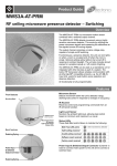
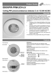
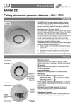
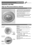
Product Guide AT-BB-IN RF input unit Overview The AT-BB-IN Input Unit provides a control interface between a lighting system and external devices such as: Button/switch plates Security systems AV equipment The unit features seven Volt-free switch inputs that can be activated by the contact closure of push-buttons, switches, or relays. Activating an input causes the unit to transmit a RF control message to other devices, triggering various actions such as recalling a scene, raising/lowering light levels, turning override on/off, starting and stopping sequences, etc. The integral RF transceiver allows wireless communication with other An-10® compatible products. All functionality is fully programmable using an infrared handset (e.g. the UHS4 or UNLCDHS) or PC control software. The unit is powered either by the internal battery or via an external 12Vdc supply. Features Front features Infrared Receiver (IR) Allows the unit to receive programming commands from an IR Handset (e.g. the UHS4) when IR Receive mode is activated (see Config Button and Status LEDs below). Config Button Press this to put the unit into IR Receive mode, enabling it to receive programming commands from an IR Handset. Status LEDs These flash Red and/or Green to indicate the following: IR Receive mode active at 1 second intervals Valid setting received Invalid setting received Back features Software reset received Factory reset received Battery (type CR2477) Provides power to the unit if an external supply is not used. Optional 12Vdc Supply Terminal To power the unit from an external supply, connect the supply to this terminal ensuring correct polarity. Refer to Technical Data on page 8 for power supply specification. Plug-in RJ45 lead and socket A short 8 core flat cable with plug that is supplied with each unit, used to connect the inputs to external devices. Installation The AT-BB-IN Input Unit can either be mounted to any suitable solid surface or concealed inside a backbox. Mounting bracket location for surface mounting. Surface Mounting Method Fit the two snap-on mounting brackets on the back side of the unit as shown in opposite. Use the holes in the mounting brackets to affix the unit to a wall or other solid surface using suitable screw fixings. Backbox Mounting Method For unsecured fixing, the unit can be simply placed inside a UK or European backbox (without fitting the snap-on mounting brackets). This enables a proprietary switch plate to be connected and screwed to the backbox. Alternatively, for secured fixing, fit the two snap-on mounting brackets on the front side of the unit as shown opposite. The unit can then be secured to the backbox using suitable fixing screws (up to M3.5). Mounting bracket location for secured backbox mounting. NOTE: The mounting bracket holes are spaced to suit either a UK (60.3mm pitch) or European (60mm pitch) backbox. CAUTION: Do not over tighten the fixing screws as this may cause the brackets to split. Electrical connection Connections to the AT-BB-IN Input Unit are made via the RJ45 lead supplied. The lead has 8 wires, comprising 7 switch inputs plus a common connection (see below). Each input can be configured (using the Switch Type parameter) for use with either momentary or latching type buttons and switches. Connect the lead wires to suitable push-buttons or switches Momentary operation is the default, used for normallyas required (see wiring examples on page 3). open push-buttons or centre-retractive type switches. Each input has two possible states: Inactive when the input is unconnected (i.e. open circuit), and Active when the input is connected to common, (i.e. during button or switch closure). Input connection identification 2 Latching operation is typically used for toggle type switches that remain in either a closed or open state. IMPORTANT NOTE: Latching Mode is not suited to battery operation due to the continuous current drain while a switch is closed. An external 12V power supply must, therefore, be connected if Latching Mode is used. Wiring examples Example 1: Using individual push-buttons Example 2: Using centre retractive switches Example 3: Using latching switches (for use with external 12Vdc supply only) IMPORTANT NOTE: Latching Mode is not suited to battery operation due to the continuous current drain while a switch is closed. An external 12V power supply must, therefore, be connected if Latching Mode is used. 3 Basic programming The functionality of the AT-BB-IN Input Unit is controlled by a number of parameters which can be changed or programmed by any of the following devices: For most basic programming operations the UHS4 handset is recommended and the following procedures are based on using this device. UHS4 Infrared Handset UNLCDHS Infrared Handset (with LCD) Step 1: Put Input Unit in receive mode To enable the AT-BB-IN Input Unit to receive programming While the unit is in receive mode send the required commands it must be put into receive mode by pressing programming commands to the unit (see Step 2 and 3). the Config Button. Valid commands will be indicated by a green LED flash. See page 1 for details of other LED responses. NOTE: While in receive mode, if no commands are received by the Input Unit within 30 seconds, the unit will automatically revert to its normal standby mode. Step 2: Set input channel addresses The addressing for an input channel defines the devices that will respond to any control messages sent by the input unit. For example, activating an input that has its Local Code set to 1, generates a control message that will only be actioned by devices that also have a Local Code of 1. To program the settings for a specific input channel you must specify the appropriate channel number (i.e.1 to 7) using the programming device. If no channel number (or channel 0) is specified, all input channels will be set to the same address. 4 Basic programming Step 3: Choose a preset configuration HINT: Where scene numbers or channel numbers are given in a Preset Configuration, these can be changed (after applying the Preset) by using the Map Scene/ Channel to Button/Input command. Refer to the UHS4 user instructions for further assistance. To simplify the programming of commonly used applications, a number of Preset Configurations are available. Preset 0 is implemented by default. Circuit mode Preset No. 0 Input 1 Input 2 Input 3 Input 4 Input 5 Input 6 Input 7 On / up Off / down On / up Off / down On / up Off / down Em Test 1 M 1 M 2 M 2 M 3 M 3 M L On Off On Off On Off Em Test Circuit 1 1 2 2 3 3 Switch type M M M M M M L Toggle 1 Toggle 2 Toggle 3 Toggle 4 Toggle 5 Toggle 6 Em Test M M M M M M L On/off On/off On/off On/off On/off On/off Em Test Circuit 1 2 3 4 5 6 Switch type L L L L L L L Function (default) 1 Circuit Switch type Function 2 Function Circuit Switch type 3 Toggle=On/off/raise/lower Function Scene mode Preset No. Toggle=On/off/raise/lower 10 Function Input 1 On Input 2 On Input 3 On Input 4 On Input 5 Up Input 6 Down Input 7 Off 11 Scene Switch type Function 1 M On / up 2 M Off / down 3 M On / up 4 M Off / down Active scene M On / up Active scene M Off / down Off M Off Scene Switch type 1 M 1 M 2 M 2 M 3 M 3 M Off M Toggle 1 Toggle 2 Toggle 3 Toggle 4 Toggle 5 Toggle 6 Off Off Switch type Function Scene M On/off 1 M On/off 2 M On/off 3 M On/off 4 M On/off 5 M On/off 6 M Off Off Switch type L L L L L L L 12 13 Function Scene Key—switch types M L Momentary push to make switch Latching switch 5 Advanced programming Input Behaviour Control Functions Changes in the state of an input (e.g. from inactive to active) generate different events that can then be used to trigger various control functions. Each type of input event can be used to trigger any of the following control functions: The events generated depend on whether momentary or latching mode is selected (via the Switch Type parameter). Momentary Mode Operation In this mode the input is usually inactive (open circuit) and only active (shorted to common) when the button or switch is pressed. This gives rise to four possible input events: Single Press Double Press Long Press – Hold (switch closed for longer than 300ms) Long Press – Release (switch opened after Long Press – Hold) Latching Mode Operation This mode is typically used for toggle type switches that remain in either a closed or open state for long periods. Latching mode, therefore, gives rise to two possible events: The table below and on page 7 gives a summary of all programmable parameters for the AT-BB-IN Input Unit. Pressed (switch closed) Released (switch open) Parameter Name Default Value Scene Select used to select a specific lighting scene. Depending on the input channel addressing both Local and/or Area scenes can be selected. Scene Raise or Lower used to increase or decrease the overall lighting levels for the currently active scene. Circuit Absolute Level used to set the level of a specific output channel. Circuit Raise or Lower used to increase or decrease the level of a specific output channel. Sequence Control used to start, stop or pause a sequence of scenes. Override Control used to select global override scenes, typically during emergency situations (e.g. fire evacuation). Emergency Test used to test device/systems for correct operation during a mains power failure. Range / Options Description Programming Devices UHS4 UNLCDHS For Device Product ID Automatically assigned by the device 1 to 999 A number used to uniquely identify each device within a range of devices that are set to the same Local Code. Building Code 1 1 to 999 A number shared by all devices that belong to the same building or system. For Each Input Channel * Switch Type Momentary Momentary, Latching Defines whether the input is used in conjunction with momentary or latching type switches. Also defines the range of events available for triggering control functions. Local Code 1 1 to 999 A number corresponding to the Local Code of all devices to be controlled by the associated input channel. Sub Local Code Not set 1 to 99 0 to clear A number corresponding to the Sub Local Code of all devices to be controlled by the associated input channel. Area Code(s) Not set 1 to 999 A number corresponding to the Area Code of all devices to be controlled by the associated input channel. Up to 10 Area Codes can be set for each input channel. None (do nothing) Scene Select Scene Raise Scene Lower Circuit Absolute Value Circuit Raise Circuit Lower Sequence Control Override Control Emergency Test Defines the type of radio control message sent to other devices. For Each Input Event Control Function 6 As per Preset 0 * * Limited to Preset Configurations Advanced programming Parameter Name Default Value Range / Options Description Programming Devices UHS4 UNLCDHS * Control Function = Scene Select Local On Scene 1 Fade Rate 1 second Timeout 255 1 to 20 0 to 255* 0 to 255* A Scene Select message comprises of three Local Scenes (On, Step and off) and three Area Scenes (On, Step and off) Local Step Scene 1 Fade Rate 1 second Timeout 255 1 to 20 0 to 255* 0 to 255* If a Local and/or Area Step Scene is specified this will be requested first followed by the Local and/or Area Off Scenes. Local Off Scene 1 to 20 20 Area On Scene 101 to 107 Fade Rate 1 second Timeout 255 101 to 220 0 to 255* 0 to 255* Area Step Scene 101 to 107 Fade Rate 1 second Timeout 255 101 to 220 0 to 255* 0 to 255* Area Off Scene 101 to 220 220 When a Scene is selected the input unit recalls the Local and/or Area On Scenes. NOTE: Area On, Step and Off Scenes are ignored unless one or more Area Codes are set for the corresponding input channel and they match the Area Codes set in any output channel. The values of the Timeout parameters associated with each scene determine whether or not the scene is actually recalled and whether or not to try and recall the next scene: Time / delay table Value Fade rate time Timeout delay period 0 No fade Ignore the Step scene 1 to 59 1 to 59 seconds, in 1 second increments 1 to 59 seconds, in 1 second increments 60 to 177 1 to 59.5 minutes, in 0.5 minute increments 1 to 59.5 minutes, in 0.5 minute increments 178 to 254 1 to 20 hours, in 15 minute increments 1 to 20 hours, in 15 minute increments 255 Infinite fade No timeout recall the specified scene only Control Function = Scene Raise Raise Action Not set Start or none Starts (or stops) raising light levels for the currently active Scene. Typically used with a Long Press Hold (to start) and Long Press Release (to stop). * Start or none Starts (or stops) lowering light levels for the currently active Scene. Typically used with a Long Press Hold (to start) and Long Press Release (to stop). * Sets the target output level for the specified Circuit Number to the value given by Output Level. The time taken for the output to fade to the new level is set by the Fade Rate. Starts (or stops) raising the output level of the specified Circuit Number. Typically used with a Long Press Hold (to start) and Long Press Release (to stop). * Starts (or stops) lowering the output level of the specified Circuit Number. Typically used with a Long Press Hold (to start) and Long Press Release (to stop). * * Control Function = Scene Lower Lower Action Not set Control Function = Circuit Absolute Level Circuit Number As per Preset 0 1 to 999 Output Level 100% (on) 0% (off) 0 to 100% Fade Rate 1 second 1 to 60 seconds Control Function = Circuit Raise Circuit Number As per Preset 0 1 to 999 Raise Action As per Preset 0 Start or none Control Function = Circuit Lower Circuit Number As per Preset 0 1 to 999 Lower Action As per Preset 0 Start or none Control Function = Override Control Override Type Not set On, off Override Action Not set Active or released Sets the specified Override global scene active or releases it. Selects whether the Override On or Override Off global scene is to be applied or released. Control Function = Sequence Control Sequence Number 1 Sequence Action Not set 1 to 99 Selects the Sequence Number to be controlled. Start, stop or pause Selects the action to be applied to the specified Sequence. Control Function = Emergency Test Test Condition Not set on or off Turns the Emergency Test feature on or off. On Test Timeout Not set 0 to 255 Sets the maximum On Test time before the feature is automatically turned off. (See note on Timeout values above). Limited to Preset Configurations * 7 Replacing the Battery Press-in the large retaining clip sufficiently to allow the two halves of the casing to be separated. Lift out the PCB module, taking care not to damage the electronic components. Slide out the battery from its mounting clip and insert a replacement battery (type CR2477 or equivalent), ensuring correct polarity. Carefully reassemble the unit, ensuring that the three retaining lugs are correctly located before clipping the casing back together. Accessing the internal battery Technical data Weight Battery 0.025kg 3Vdc lithium battery, type CR2477 (supplied with unit) Battery Life Greater than 7 years with typical usage Optional External Supply Requirements: Supply Voltage 12Vdc regulated Supply Current 50mA max. Supply Power 600mW max. Terminal Capacity 2.5mm2 Order code Region Radio frequency Compliance blank European Union 868MHz EN300 220-2 V2.1.2 EN301 489-1 V1.8.1 EN301 489-3 V1.2.1 -A2 Australia & New Zealand 915MHz Dimensions - without brackets Dimensions - with brackets AS/NZS 4268:2008 Receiver Class 2 Transmitter Duty Cycle <10% on g3 band (default band) <0.1% on g2 band <1% on g1 band Range The maximum RF range between An-10 devices is 100m in free air and up to 30m indoors. However the materials used within a building will vary and this will impact upon the RF range. In reality the nature of how the An-10’s hybrid-mesh works means that in most scenarios the individual range of an An-10 product will not be important. Temperature Humidity Material (casing) 0ºC to 35ºC 5 to 95% non-condensing Flame retardant polycarbonate Hereby, CP Electronics Ltd, declares that this AT-BB-IN is in compliance with the essential requirements and other relevant provisions of Directive 1999/5/EC. The declaration of conformity may be obtained for CP Electronics Ltd Brent Crescent, London, NW10 7XR, UK. Part numbers EBDSPIR-AT-PRM EBDSPIR-AT-DD EBDSPIR-AT-AD AT-SL-R AT-SL-R-SA AT-SL-DDR AT-SL-DDR-SA AT-SL-ADR AT-SL-ADR-SA VITM4-ATMOD VITM6-ATMOD-AD VITM6-ATMOD-DD UNLCDHS FM 45789 RF Ceiling PIR presence detector – switched RF Ceiling PIR presence detector – DALI/DSI dimming RF Ceiling PIR presence detector – 1-10V dimming RF relay controller RF relay controller (standalone) RF DALI/DSI + relay controller RF DALI/DSI + relay controller (standalone) RF 1-10V + relay controller RF 1-10V + relay controller (standalone) RF Switching module RF VITM6 1-10V module RF VITM6 DALI/DSI module Universal LCD IR handset EMS 534520 Due to our policy of continual product improvement CP Electronics reserves the right to alter the specification of this product without prior notice. 8 If any of these symbols are on the product or battery, the product or battery must be disposed of in the correct manner and must not be treated as household or general waste. C.P. Electronics Ltd Brent Crescent London NW10 7XR United Kingdom Tel: + 44 (0) 333 900 0671 Fax: + 44 (0) 333 900 0674 www.cpelectronics.co.uk [email protected] Ref: #WD371 Issue 2