1
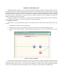
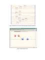
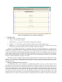
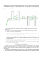
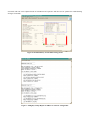
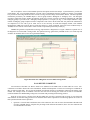
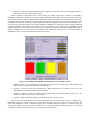
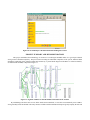
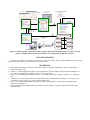
header for SPIE use
Model-based Testability Assessment and Directed Troubleshooting of
Shuttle Wiring Systems
Somnath Deba, Charles Domagalaa, Roshan Shresthaa, Venkatesh Malepatia, and Kevin Cavanaugha
Ann Patterson-Hineb, Dwight Sanderferb, and Jim Cockrellb
a
Qualtech Systems, Inc., Suite 501, 100 Great Meadow Road, Wethersfield, CT 06109
b
NASA-ARC Research Center, Moffett Field, CA 94035
ABSTRACT
As the space shuttle ages, it is experiencing wiring degradation problems, including arcing, chaffing, insulation
breakdown and broken conductors. A systematic and comprehensive test process is required to thoroughly test and QA the
wiring systems. The NASA Wiring Integrity Reseach (WIRe) team recognized the value of a formal model based analysis
for risk assessment and fault coverage analysis using our TEAMS toolset and commissioned a pilot study with QSI to explore
means of automatically extracting high fidelity multisignal models from wiring information databases.
The MEC1 Shuttle subsystem was the subject of this study. The connectivity and wiring information for the model was
extracted from a Shuttle Connector Analysis Network (SCAN) electronic wirelist. Using this wirelist, QSI concurrently
created manual and automatically generated wiring models for all wire paths associated with connector J3 on the MEC1
assembly. The manually generated model helped establish the rules of modeling. The complete MEC1 model was
automatically generated based on these rules, thus saving significant modeling cost. The methodology is easily extensible to
the entire shuttle wiring system.
This paper presents our modeling and analysis results from the pilot study along with our proposed solutions to the
complex issues of wiring integrity assessment problem.
Keywords: wiring, arcing, chaffing, insulation breakdown, multisignal, Wire Integrity Program, TEAMS
INTRODUCTION
We have recently completed a pilot study on the Space shuttle wiring system commissioned by the Wiring Integrity
Reseach (WIRe) team at NASA Ames Research Center. As the space shuttle ages, it is experiencing wiring degradation
problems, including arcing, chaffing, insulation breakdown and broken conductors [1]. A systematic and comprehensive test
process is required to thoroughly test and QA the wiring systems. The NASA WIRe team recognized the value of a formal
model based analysis for risk assessment and fault coverage analysis using our TEAMS toolset. However, wiring systems are
complex and involve over 50,000 wire segments. Therefore, NASA commissioned this pilot study with QSI to explore means
of automatically extracting high fidelity multisignal models from wiring information databases.
The intent of the pilot study was to investigate the feasibility of automatically creating a TEAMS model [2] for a subset
of the space-shuttle wiring. The model could be used by the TEAMS toolset [3] to guide the technician in the wiring
diagnosis and quality assurance process while helping NASA engineers monitor the extent of wiring failure modes covered
by the testing process. The TEAMS toolset could also provide the technician with the necessary tools to electronically log all
maintenance activities, and help automate the maintenance process [4], while preserving all the existing checks and balances.
All of the wiring information required for creating the TEAMS model was supplied via a Shuttle Connector Analysis
Network (SCAN) electronic wirelist. This partial wirelist contained all the wiring information relative to the MEC1
assembly. Using this NASA supplied SCAN wirelist, QSI concurrently created manual and automatically generated TEAMS
wiring models for all wire paths associated with connector J3 on the MEC1 assembly. The manually generated model helped
establish the rules of modeling. The automated model was compared against the manual model to verify that the
automatically generated model accurately portrayed the actual shuttle wiring. Once it was ascertained that the automatically
generated model was identical to the one created manually, the complete MEC1 model was generated, thus saving significant
modeling cost. We also performed testability analysis on the system to determine the capability of the resulting wire
maintenance system in detecting and isolating faults. These parameters help establish the effectiveness of a wire monitoring
and troubleshooting program
MODELING METHODOLOGY
TEAMS multisignal modeling [2, 5] is a hierarchical modeling methodology. Models can be built top-down or bottomup. In the present effort we pursued a bottom up approach, where we first created a library of connector and wire types and
then interconnect them as per the SCAN wirelist to generate the complete model. To automatically generate the TEAMS
model, the raw data from the SCAN wirelist was converted into a format more compatible with TEAMS. A filter was written
to reformat this into a TEAMS model. An import function was added to TEAMS to read the TEAMS-SCAN model over
ODBC and automatically generate the model.
In making the models of the components, we made some basic assumptions regarding failure modes of components,
level of repair, testing methods, etc. These are described in the following subsections.
1. Modeling of connectors
For connectors, it was assumed that only the pins of the connector can fail, and that the possible failure modes of the
pins are:
1.
PushedPin or open circuit caused by pushed pins,
2.
PinCorrosion or resistive contact, possibly caused by corroded pins or poor contact with mating pin, and
3.
BentPin or shorts possibly caused by a bent pin shorting to an adjacent pin, or a piece of metal shorting two or more
pins.
Figure 1: Connector Pin Module
NASA repair procedures require that the pins in connectors be repaired or replaced, rather than replacing the entire
connector. Therefore, the connectors were labeled as modules, and the pins as (replaceable) components with the three failure
modes discussed previously (see Fig. 1). The connector was modeled as a collection of pins with the appropriate pin labels
(see Fig. 2). To avoid unnecessary undetected failures, only the wired pins were represented in the TEAMS model.
Figure 2: Bottom part of a connector module showing the (wired) pin components
Figure 3: Failure modes of a wire
Figure 4: TEAMS model of a two-conductor shielded wire.
2.
Modeling of wires
Wire failure modes were defined as follows:
1.
Open, e.g., due to a broken conductor,
2.
DeltaResistance, e.g., oxidized or frayed conductor making partial connections,
3.
HardShort , e.g., a short circuit to ground or adjacent conductors due to damaged insulation, and
4.
BadDielectric, e.g., worn or degraded insulation allowing arcing when a high voltage is applied, possibly causing
intermittent, and potentially hazardous, electrical discharges under normal operation.
The wires were modeled based on their type (conductor, twisted pair, twisted pair shielded, etc.). A library of wire
“components” was created based on the wire types listed in the SCAN wirelist. Consistent with NASA repair procedures, a
twisted wire was modeled as a single wire “component” since it would be replaced as a single unit. The “Wire Type” and
“Cable Descriptor” fields of the SCAN database uniquely define bundles. For each wire (or conductor) in the wire type, we
inserted a sub-component with the appropriate failure modes. The shield, however, has only one failure mode, representing a
broken shield or ground path. Fig. 3 presents an example model of a wire showing the failure modes. Fig. 4 presents the
model of 2 conductor shielded wire of gauge F wires (F2S).
The model can easily be updated to represent actual wiring repair practices used by NASA or changes in the current
practices. If, for example, it is determined that a particular harness cannot be repaired and must be replaced as an entire
assembly, then the repair label of that particular harness would be revised, leaving the previously defined repair labels for the
other harnesses intact.
3. Modeling of Mate/Demate status of connectors
The mate/demate status of each connector was modeled using switches (see Fig. 5). These switches can be
programmatically opened and closed in TEAMS and TEAMATE/TEAMS-RT to simulate the mated and demated states of
the connectors. When connectors are demated, they provide access to the pins and various tests can be performed to assess
fault coverage and isolation. We have created System modes, which should be used when running the analysis. The first one
is labeled “CompleteHarness”. Selecting this mode will simulate all connectors being mated to their mating connector with
the exception of the last connector in each wire path. Running the analysis in this mode will generally result in large
ambiguity groups caused by the inability to fault isolate paths containing multiple wire segments and connectors. The second
System mode we have created is called “DisconnectAll”. Selecting this mode will simulate all connectors being demated,
thus allowing testing on the pins of all connectors. Running the analysis in this mode will result in much smaller ambiguity
groups. Additional system modes can be defined or changed as needed. If it is known that some connectors in the wiring
harness cannot be accessed, then System modes can be defined to allow demating of all but these connectors. In the actual
application, the mate/demate status of the connector would be read from SCAN and automatically represented with the
proper status in the TEAMS model.
Figure 5: Partial Wiring Harness Model showing switches to model mate/demate status of each connector
4.
Modeling of tests
The final step was to add tests to address the failure modes. The tests defined for the wiring model are as follows:
1.
Continuity – To detect open wires and pushed pins.
2.
Isolation – Involves shorting all other pins to ground and then measuring resistance between the pin being tested
and ground to assure pin is isolated from all other pins and ground.
3.
Delta Resistance – Involves measuring DC resistance through a wire path and comparing it to a predetermined
limit. It will detect open wires, pushed pins, and high resistance paths caused by corroded pins, poor contact with
mating pins, and broken or frayed wires making partial contact. It will also detect wires shorted to ground.
However, based on the feedback at our review meeting, we disabled these tests, as they are currently not part of the
standard test procedures.
4.
Complex Impedance – This test will detect changes in resistance (wire shorts, opens and degradations) and
reactance (degradation in insulation leading to capacitive coupling).
5.
DWV (Dielectric Withstanding Voltage) – Similar to Isolation test except a voltage signal is applied and gradually
increased to detect wire or pin breakdown.
TESTABILITY ANALYSIS RESULTS
Testability analysis was performed using TEAMS to produce reports that provide failure mode coverage metrics and
generate optimized test strategy. The results of the analysis are presented in a number of formats. The primary testability
report is the Testability Figures Of Merit Summary (TFOMS) Report. The TFOMS Report for the MEC1 wiring model is
illustrated in Fig. 6.
The failure rates of the individual wires and connectors were set to 1 per million hours. However, with the sheer number
of wires and pins, the mean time to first failure is 1406 hours. Such parameters, along with estimates of time and cost
associated with tests can be adjusted based on field MTTF and experience and then used to optimize the troubleshooting
strategies of TEAMS.
Figure 6: TFOM Summary for the MEC1 wiring model
Figure 7: Ambiguity Groups Report for MEC1 J3 connector wiring model
The “Test Options” section of the TFOMs report lists the options used for the analysis. “System Statistics” provides the
model details. The “Test Algorithm Statistics” provides a list of information about the resulting test strategy. The TFOMs
box presents the Percentage Fault Detection or Fault Coverage and Percentage Fault Isolation metrics. The most important
information provided by the TFOMS Report is the bar graph entitled “Histogram of Ambiguity Size”. The histogram
provides a graph of the relative number of ambiguity group sizes. The list of specific components comprising the individual
ambiguity groups is provided in the “Ambiguity Groups (dynamic)” test report (see Fig. 7). The analysis indicates a large
number of ambiguity groups comprised of three components. This is due to the fact that most wire paths in the sub harnesses
are comprised of a wire with a pin at either end. If it was necessary to break this ambiguity further, Time Domain
Reflectometer (TDR) tests could be used to isolate the failure to a single component. Such tests can be modeled easily in
TEAMS, but were left out of the model to reflect current test procedures practiced by NASA [6].
TEAMS also generates an optimized test strategy represented in a diagnostic tree. Figure 8 illustrates a partial view of
the diagnostic tree for the MEC1 wiring model. The optimized strategy generated by TEAMS involves over 1000 steps and
would be an enormous task if it were to be generated manually.
Figure 8: Partial view of Diagnostic Tree for MEC1 wiring model
NASA REVIEW COMMENTS
Two iterations of the MEC1-J3 harness model were submitted to the WIRe team at NASA-ARC for review. Teleconferences were held to discuss the source information, models and assumptions. A final review meeting was conducted on
May 8, 2000 at NASA-ARC. Peer review and feedback from domain experts are invaluable in improving the fidelity of the
models. For example, based on feedback received in the final review meeting, the model was revised to accommodate
isolation and Dielectric Withstanding Voltage tests consistent with prevailing NASA testing practices.
From the review process, it became clear that the WIRe team was more concerned with coverage of wires than with
fault isolation. Several interesting questions were raised that merit further exploration. The following captures the essence of
these questions and the answers provided:
•
Question 1: Given the mate and demate states of the connectors, how can one assess the maximum achievable fault
coverage? TEAMS analysis computes the percentage fault detection and isolation, but it does not enumerate the
covered and uncovered wires.
•
Question 2: Connector 5 will be demated Tuesday for repairs. If I test all cable runs accessible through connector 5,
what percent of all cable runs will I have tested?
Answer: Fortunately, this problem can be solved utilizing our existing tools. Figure 9 presents a screendump of
TEAMS-RT, which takes a fraction of a second to compute the numbers for the MEC1 model. The top half of the screen
shows the list of failure modes (left column) and the mate-demate status (right column). The lower half of the screen shows
the components that will be covered (Good) and still untested (Unknown) if testing were to be performed utilizing the current
configuration of connectors. The Modes, or Mate/Demate status can be set programmatically from the SCAN database. Also,
if the tests were performed and pass/fail tests results submitted to TEAMS-RT, it would also be able to compute the Bad and
Suspected components, still within a second of processing time. TEAMS-RT, when combined with TEAMS-KB, can also
retain the state of the system, and quantify incremental test coverage, as more and more connectors are demated and tested. In
addition, TEAMATE can be used to guide the technician(s) and expedite the testing process. A web-based version of
TEAMATE (see Fig. 11) was also demonstrated in the review meeting.
Figure 9: Screendump of TEAMS-RT assessing fault coverage for MEC1 system.
•
Question 4: Given a wire network and given enough time to demate/test 2 connectors only, which connectors do I
demate and test to maximize the number of cable runs tested?
•
Question 5: I need to test the circuit containing run E. Which connector pair do I demate to access E, but use
opportunities to test maximum number of other cable runs
•
Question 6: Suppose connector 8 is hidden and inaccessible. What is the greatest number of wire runs I can
possibly tests? How many connectors must I demate?
•
Question 7: What are the fewest number of connectors demated to test all wire runs?
Answer: All of the above questions, can be easily formulated as set-covering problems subject to constraints (e.g.,
inaccessible connectors, cost/time budget) and efficient search algorithms can be developed to solve the problems. The
models and TEAMS-RT’s ability to evaluate coverage will be essential components required for evaluation of the cost
function to be optimized by the search process. While there is no off-the-shelf solution to these questions, we can develop
comprehensive solutions to these problems given the opportunity in the near future.
Figure 10: Screendump of a Web-based TEAMATE diagnosis session.
PROJECT SUMMARY AND RECOMMENDATIONS
This project established the methodology for creation of a multi-signal TEAMS model of a typical space-shuttle
wiring circuit of medium complexity. The process started creating the individual components of the system, and then added
dependency paths that closely followed actual interconnectivity. A partial block diagram of the MEC1 J3 connector harness,
as modeled with TEAMS, is depicted in Figure 11.
Figure 11: Segment of MEC1 J3 TEAMS Model Generated from SCAN data
By establishing some basic rules on wire failure modes and test methods, we were able to automatically create a MEC1
wiring assembly model in TEAMS. The many features available with the TEAMS tool helped to greatly simplify the task and
perform the analysis. The resulting model closely resembles the physical structure of the wiring circuit, thus allowing updates
to be made quickly and easily.
This project illustrated how TEAMS can be used to assess testing methods and to create a diagnostic strategy tailored to
specific needs. QSI demonstrated that the run-time tools, TEAMS-RT and TEAMATE, can handle the analysis and runtime
of the MEC1 subsystem in a simple laptop computer – and feel confident that the solution will scale to about two orders of
magnitude higher than the MEC1 model. Based on the work accomplished in the pilot project, the following
recommendations were provided:
1.
Implement the TEAMS analysis as an important aspect of spacecraft wiring design and life cycle support (from
analysis to support).
2.
Research the concept of using the optimized, dynamic model based reasoner (TEAMATE) to drive the wiring test
equipment.
3.
Move forward to link wiring technical manuals (Interactive Electronic Technical Manuals - IETM) to TEAMATE
for class V IETM.
4.
Set up a web-based, remote wiring diagnostic system to enhance troubleshooting and maintenance across NASA
centers and contractors.
5.
Research the aspect of embedding the run-time, model based diagnostics (TEAMS-RT) on the vehicle to diagnose
wiring problems in real time.
A copy of our project report along with these recommendations were incorporated in the final wire team report [6].
THE ROAD AHEAD
The TWA 800 and SwissAir 111 accidents both involved electrical wiring failures in commercial aircraft. Further, it
has been shown since these accidents occurred that they might have been prevented if a suitable wire testing program had
been in place. Industry practice then and even now relies primarily upon visual inspection methods to identify damaged and
degrading wiring prior to failure. These inspection methods have been proven to be inadequate in identifying wiring
anomalies. In addition, this experience is not limited to commercial aviation, but is also true for the military services and
even the NASA space shuttle program. As understanding of the scope of this problem improves, the need for comprehensive
wire management programs becomes self-evident. Such a program would track the condition of a wire from the day of
manufacture through its entire service life complete with appropriate testing and maintenance records. Included is the need
for safety assessments to document the practical trades that will be required in terms of periodicity of inspection, inspection
methodology, and functional testing. This type of program would not only substantially improve safety, but also has the
potential to reduce “no-fault-found” component removals, labor inspection time, aircraft downtime (and therefore aircraft
readiness), and other airline cost drivers.
The Wire System Safety Interagency Working Group (IWG), at the direction of the White House Commission for
Aviation Safety and Security, issued D-181 SN470351 on 29 June 2000 requesting information to assist government agencies
in dealing with the challenges surrounding Wire System Safety. This Commerce Business Daily announcement requested
information on ongoing activities that include: a) a better understanding of degradation mechanisms, b) detection/inspection
techniques, c) methods of mitigation, and d) improved wiring systems. In response to this solicitation, GRC International
assembled a team of companies that have been involved in the issues surrounding wire safety for many years, and formed the
Wire Integrity Program to develop a comprehensive program for managing wire integrity. The teaming of these companies
allows for immediate implementation of existing technologies specifically designed to address wiring system problems. The
companies participating in this endeavor are Honeywell, Inc., GRC International, Inc., DIT-MCO International, Inc.,
Lectromechanical Design Company, Phoenix Aviation & Technology and Qualtech Systems, Inc.
A resultant Wire Integrity Program includes vehicle modeling, test planning, and monitoring, testing and health
assessment and data management. The Wire Integrity Support Environment (WISE, see Fig. 12) brings together the advanced
modeling and analysis features of TEAMS and MultiLinx to perform wiring system modeling, failure analysis, diagnostic
analysis, data logging, automatic test generation, optimized test and maintenance strategy, wire system diagrams/architecture,
and intelligent/dynamic/reasoning for wire testing and maintenance. Honeywell is currently committed to leading the
integration of QSI’s TEAMS toolset and GRCI’s Multilinx tool, to develop the first iteration of the WISE software by mid2001.
Graphical Models
Diagnostic
Metrics
Wire System Source Data:
Wiring table
Mating table
Parts List
System Architecture
TEAMS-KB
TEAMS
• FD/FI Assessment
• DFT Analysis
• FMECA
• Optimized Diagnostic
Strategy (Test Plans)
Tracking & Trending
On-Line Wire Test Plans
Test & Maint.
Mgmt
Model Export
Model Export
Parts Removal and
Replacement
History
FD Coverage
Test Metrics
Trending/Prognostics
Test Schedules
1
Model and Test
Data Exchange
Configuration Data
Test Results/History/Logs
TEAMATE
•Smart Test Sequence
•Setup and Test
Instructions
•DynamicReasoner
•Auto Records/Logging
2
Intelligent, Interactive
Wire Test & Maintenance
Wire Harness Test Prompts
Next Best Test
Request Test Results
Test Results
MultiLinx
• Wiring Architecture
• Schematic Generation
• Data Archiving
• Failure Analysis
• Automated Test
Generation (ATG)
Automated Test Generation
Bulk Testing
Del Test
TDR
Optical
Methods
WIDAS
TBD
Figure 12: Fully Integrated, Comprehensive Wire Integrity Support Environment (WISE) - provides a network
(Internet) capable, thin client software solution for ease of deployment, maintenance, and use.
ACKNOWLEDGMENTS
Portions of this work were funded by a pilot study on the Space shuttle wiring system commissioned by the Wiring
Integrated Reseach (WIRe) team at NASA Ames Research Center.
REFERENCES
1.
2.
3.
4.
5.
6.
Space Shuttle Independent Assessment Team Report, Report to Associate Administrator, Office of Space Flight,
October-December, 1999.
S. Deb et. al. “Multi-Signal Flow Graphs: A novel Approach for System Testability Analysis and Fault Diagnosis,” in
Proc. IEEE AUTOTESTCON, Anaheim, CA, pp. 361-373, Sept. 1994.
S. Deb, et. al. “QSI Integrated Diagnostics Toolset,” 1997 IEEE AUTOTEST Conference, Anaheim, CA, September
1997.
S. Ghoshal et. al “An Integrated Process for System Maintenance, Fault Diagnosis and Support,” Proceedings of the
1999 IEEE Aerospace Conference, Aspen, Colorado, March 1999.
S. Deb, et. al. “Multisignal Modeling for Diagnosis, FMECA, and Reliability” invited paper in 1998 IEEE SMC
conference, San Diego, CA
Wiring Integrity Research (WIRe) Pilot Study, Design for Safety Initiative, Document Number AOSP-0001-XB1,
August 25, 2000.