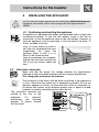
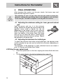
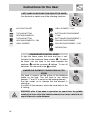
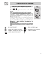
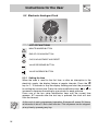
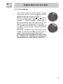
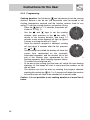
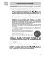
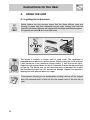
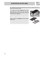
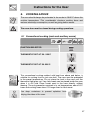
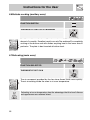
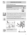
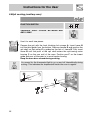
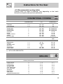
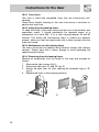
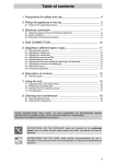
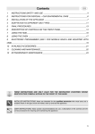
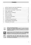
1
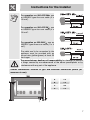
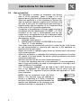
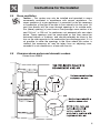
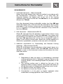
smeg
���
��� technology with style
installation
and operating
instructions
A31X
freestanding
cooker
Table of Contents
1.
PRECAUTIONS FOR SAFETY AND USE ____________________________ 4
2.
INSTALLING THE APPLIANCE ____________________________________ 6
3.
ADAPTATION TO DIFFERENT TYPES OF GAS______________________ 12
4.
FINAL OPERATIONS ___________________________________________ 14
5.
DESCRIPTION OF CONTROLS___________________________________ 15
6.
USING THE HOB ______________________________________________ 22
7.
USING THE OVENS ____________________________________________ 24
8.
ACCESSORIES AVAILABLE _____________________________________ 25
9.
COOKING ADVICE _____________________________________________ 27
10.
CLEANING AND MAINTENANCE _________________________________ 35
11.
EXTRAORDINARY MAINTENANCE _______________________________ 40
Thank you for choosing our product.
We advise you to read this manual carefully. It contains all necessary
instructions for maintaining unaltered the appearance and functional
qualities of the cooker.
INSTRUCTIONS FOR THE INSTALLER: these are intended for the
authorized person who is to check the gas supply system and install,
commission and test the appliance.
INSTRUCTIONS FOR THE USER: these provide recommendations for
use, a description of the controls and the correct procedures for cleaning
and maintaining the appliance.
3
Presentation
1.
PRECAUTIONS FOR SAFETY AND USE
THIS MANUAL IS AN INTEGRAL PART OF THE APPLIANCE. TAKE GOOD
CARE OF IT AND KEEP IT TO HAND THROUGHOUT THE COOKER'S LIFE
CYCLE. USERS ARE ADVISED TO READ THIS MANUAL AND ALL THE
INSTRUCTIONS IT CONTAINS BEFORE USING THE COOKER. ALSO KEEP
THE SET OF NOZZLES PROVIDED IN A SAFE PLACE. INSTALLATION MUST
BE CARRIED OUT BY QUALIFIED STAFF IN COMPLIANCE WITH THE
RELEVANT REGULATIONS. THIS APPLIANCE IS INTENDED FOR
HOUSEHOLD USE AND COMPLIES WITH THE EEC DIRECTIVES CURRENTLY
IN FORCE. THE APPLIANCE IS BUILT TO PROVIDE THE FOLLOWING
FUNCTION: COOKING AND HEATING FOODS; ALL OTHER USES ARE TO BE
CONSIDERED IMPROPER.
THE MANUFACTURER DECLINES ALL LIABILITY FOR USES OTHER THAN
THOSE STATED ABOVE.
NEVER LEAVE PACKAGING RESIDUES UNATTENDED IN THE HOME.
SEPARATE WASTE PACKAGING MATERIALS BY TYPE AND CONSIGN THEM
TO THE NEAREST SEPARATE DISPOSAL CENTRE.
THE APPLIANCE MUST BE CONNECTED TO EARTH IN COMPLIANCE WITH
ELECTRICAL SYSTEM SAFETY REGULATIONS.
THE PLUG TO BE CONNECTED TO THE POWER SUPPLY LEAD AND THE
RELATIVE SOCKET MUST BE OF THE SAME TYPE AND COMPLY WITH THE
RELEVANT REGULATIONS.
THE POWER SUPPLY SOCKET MUST BE ACCESSIBLE EVEN AFTER THE
APPLIANCE HAS BEEN BUILT-IN.
NEVER DISCONNECT THE PLUG BY PULLING ON THE POWER SUPPLY
LEAD.
IMMEDIATELY AFTER INSTALLATION, CARRY OUT A QUICK TEST ON THE
APPLIANCE FOLLOWING THE INSTRUCTIONS PROVIDED LATER IN THIS
MANUAL. IF THE APPLIANCE FAILS TO OPERATE, DISCONNECT IT FROM
THE ELECTRICAL MAINS AND CONTACT YOUR NEAREST SERVICE CENTRE.
NEVER ATTEMPT TO REPAIR THE APPLIANCE YOURSELF.
AFTER EACH USE OF THE APPLIACE, ALWAYS CHECK THAT THE CONTROL
KNOBS ARE TURNED TO
(OFF).
NEVER PLACE FLAMMABLE OBJECTS IN THE OVENS: IF THEY SHOULD
ACCIDENTALLY BE SWITCHED ON, THIS MIGHT CAUSE A FIRE.
THE NAMEPLATE WITH THE TECHNICAL DATA, SERIAL NUMBER AND MARK
IS IN A VISIBLE POSITION IN THE STORAGE COMPARTMENT.
THE NAMEPLATE MUST NEVER BE REMOVED.
4
Presentation
NEVER PLACE PANS WITH BOTTOMS WHICH ARE NOT PERFECTLY FLAT
AND SMOOTH ON THE HOB PAN STANDS.
THE APPLIANCE BECOMES VERY HOT DURING USE. TAKE CARE NOT TO
TOUCH THE HEATING ELEMENTS INSIDE THE OVEN.
THIS APPLIANCE MUST NEVER BE INSTALLED ON A STAND.
INSTALL THE APPLIANCE SO THAT WHEN DRAWERS OR DOORS OF UNITS
INSTALLED AT HOB HEIGHT ARE OPENED, ACCIDENTAL CONTACT WITH
PANS ON THE HOB IS NOT POSSIBLE.
NEVER USE PANS OR GRIDDLE PLATES WHICH PROJECT BEYOND THE
OUTSIDE EDGE OF THE HOB.
THE APPLIANCE IS INTENDED FOR USE BY ADULTS. KEEP CHILDREN AT A
SAFE DISTANCE AND NEVER ALLOW THEM TO PLAY WITH IT.
REPLACED APPLIANCES MUST BE TAKEN TO A SPECIAL GARBAGE
COLLECTION CENTRE.
THIS APPLIANCE IS DESIGNED FOR COOKING FOOD AND IT SHALL NOT BE
USED AS A SPACE HEATER.
WHERE THIS APPLIANCE IS INSTALLED IN MARINE CRAFT OR IN
CARAVANS, IT SHALL NOT BE USED AS A SPACE HEATER
DO NOT SPRAY AEROSOLS IN THE VICINITY OF THIS APPLIANCE WHILE IT
IS IN OPERATION.
BEFORE THE APPLIANCE IS PUT INTO OPERATION, ALL THE LABELS AND
PROTECTIVE FILMS APPLIED INSIDE OR OUTSIDE MUST BE REMOVED.
The manufacturer declines all responsibility for injury or damage
caused by failure to comply with the above regulations or deriving from
tampering with even just one part of the appliance and the use of nonoriginal spare parts.
5
Instructions for the Installer
2.
INSTALLING THE APPLIANCE
It is the law that all gas appliances are installed by authorised persons.
Clearance around the cooker must comply with the requirements of
AS5601.
2.1 Positioning and levelling the appliance
The appliance is equipped with wheels and adjustable feet to simplify the
positioning procedure. To use the front wheels, screw in the foot as
shown here, so that the appliance rests on the front wheels. However, to
allow the appliance to be moved freely it must be lifted at the back. To
do this, proceed as follows:
use a 10 socket wrench to screw in
the 2 hex nuts underneath the oven
compartment: this raises the
appliance either to level it or to
allow it to be moved around.
Once all procedures are complete,
retighten the front feet and the hex
nuts to set the cooker stable and
level.
2.2
Electrical connection
Make sure that the power line voltage matches the specifications
indicated on the rating plate located inside the storage compartment.
This rating plate must never be removed.
The connection to the mains shall be done conforming to the regulations
in force. Check that the power line is adequately grounded. Do not use
reducers, adapters or shunts. On the power line, install an omnipolar cutoff device with contact cut-off distance greater than or equal to 3 mm,
located in an easily accessible position near the unit.
The connection terminals are
located at the rear of the
appliance.
For
electrical
connections
see
following
diagram. To access, remove
the rear cover.
6
Instructions for the Installer
For operation on 380-415V3N∼: use
an H05RR-F-type five-core cable (5 x
1.5 mm2).
For operation on 380-415V2N∼: use
an H05RR-F-type four-core cable (4 x
2.5 mm2).
For operation on 220-240V∼: use an
H05RR-F-type three-core cable (3 x 4
mm2).
The cable end to be connected to the
appliance must be provided with an
ground wire (yellow-green) at least 20
mm longer.
The manufacturer declines all responsibility for damage to persons
or things caused by non-observance of the above prescriptions or by
interference with any part of the appliance.
Overall dimensions: location of gas and electrical connection points (all
measures in mm).
A
110
B
770
C
150
D
170
7
Instructions for the Installer
2.3
Gas connection
This appliance is suitable for installation with Natural
Gas or ULPG (propane). Refer to page 12 for the
relevant burner pressure and appropriate injector sizes.
When the appliance is to be connected to Natural Gas
then the pressure regulator supplied must be fitted to the
gas inlet. A test point (for checking the gas pressure) is
supplied either with the regulator or as a separate fitting
in the case of ULPG (propane) appliances.
Connection of the appliance to the gas supply must be in
accordance with the requirements of AS5601. A ½” BSP
connector at the inlet is recommended and the gas
supply line to the appliance must be of adequate length
to allow sufficient withdrawal of appliance for service or
disconnection and be:
1. annealed copper pipe or;
2. flexible hose according to AS/NZ1869 & be at least
Class “B”, 10 mm diameter.
The cooker must be installed with provision to allow the gas to be turned
off and disconnected for servicing and removal of the appliance as
required from the gas supply.
Before the cooker is operated make certain all relevant parts are placed
in the correct position.
When the installation is completed the installation connections of cooker
will require to be leak tested, the burner operating pressure and flame
checked and adjusted.
Warranty service calls do not cover these adjustments!
To check the operating pressure of the appliance it is recommended at
least 2 large size burners are used. Ensure appliance is secured to wall
when installation is completed.
N.G. The regulator supplied must be fitted to the ½ BSP thread at the
rear of the appliance. An approved manual shut-off valve must be
installed. The N.G. regulator must be checked and adjusted to 1.0kPa
after installation.
ULPG: Can be connected to the inlet fitting
directly. The pressure must be checked to
ensure it is operating at 2.75kPa. A separate
test point fitting must be installed between the
piping & the appliance for the pressure to be
checked to ensure it is operating at 2.75kPa.
8
Instructions for the Installer
2.4
Room ventilation
Caution – This cooker may only be installed and operated in rooms
permanently ventilated in accordance with current regulations. For
proper operation of a gas appliance it is essential for the air necessary
for combustion of the gas to be able to flow naturally into the room. Air
must flow directly into the room through openings in its outside walls.
This (these) opening (s) must have a free passage cross-section of at
least 100 cm2, or 200 cm2 for appliances not equipped with gas safety
device. These openings must be constructed so that they cannot be
obstructed indoors or outdoors, and should preferably be close to the
floor on the side opposite to the combustion gas discharge point. If it is
not possible to make the openings in the room where the cooker is
installed, the necessary air may be taken from an adjoining room,
proveded it is not a bedroom or a room with fire risk.
2.5
Clearance above and around domestic cookers
Extract from AS5601
9
Instructions for the Installer
REQUIREMENTS
1
Overhead clearances – (Measurement A)
Range hoods and exhaust fans shall be installed in accordance with
the manufacturer’s instructions. However, in no case shall the
clearance between the highest part of the hob of the cooking
appliance and a range hood be less than 600 mm or, for an overhead
exhaust fan, 750 mm.
Any other downward facing combustible surface less than 600 mm
above the highest part of the hob shall be protected for the full width
and depth of the cooking surface area in accordance with Clause
5.12.1.2. However, in no case shall this clearance to any surface be
less than 450 mm.
2
Side clearances – (Measurements B & C)
Where B, measured from the periphery of the nearest burner to any
vertical combustible surface, is less than 200 mm, the surface shall
be protected in accordance with Clause 5.12.1.2 to a height C of not
less than 150 mm above the hob for the full dimension (width or
depth) of the cooking surface area. Where the cooking appliance is
fitted with a ‘splashback’, protection of the rear wall is not required.
3
Additional requirements for Freestanding and Elevated Cooking
Appliaces – (Measurements D & E)
Where D, the distance from the periphery of the nearest burner to a
horizontal combustible surface is less than 200 mm, then E shall be
10 mm or more, or the horizontal surface shall be above the trivet.
See insets above.
NOTES
1
2
3
4
5
10
Requirement 3 does not apply to a freestanding or elevated
cooking appliance which is designed to prevent flames or the
cooking vessels from extending beyond the periphery of the
appliance.
The ‘cooking surface area’ is defined as that part of the
appliance where cooking normally takes place and does not
include those parts of the appliance containing control knobs.
For definition of hob, see Clause 1.4.64.
For definition of trivet, see Clause 1.4.109.
Consideration is to be given to window treatments when
located near cooking appliances. See Clause 5.3.4.
Instructions for the Installer
2.6
Instruction for wall fixing
In order to prevent accidental tipping of the appliance, for example by a
child climbing onto the open door, the stabilizing means must be
installed. Please refer to instruction below.
1)
2)
3)
4)
Fix the screw to the wall and hook the chain (B);
Hook the chain to the hole positioned at the rear of the cooker by the
gas pipe (A);
Once the chain is in position, push the cooker against the wall;
The height of the screw hole from floor level must not exceed 800
mm (C).
A
B
C
11
Instructions for the Installer
3. ADAPTATION TO DIFFERENT TYPES OF GAS
Before performing any cleaning or maintenance work, switch off the
power supply to the appliance.
The cooking hob of the cooker is preset for natural gas at a pressure of
1.0 kPa. In the case of functioning with other types of gas the burner
nozzles must be changed and the minimum flame adjusted on the gas
taps. Replace the burner nozzles as indicated in the table of the gas to be
used.
3.1 Changing nozzles
1.
2.
3.
12
Extract the grids and remove all the caps and flame-spreader
crowns;
unscrew the burner nozzles with a 7 mm socket wrench;
proceed with replacing the burner nozzles in accordance with the
table for the gas in question.
Instructions for the Installer
3.2 Burner and nozzle characteristics table
Burner
Auxiliary
Semi rapid
Rapid
WOK
Fish pan
Burner
Auxiliary
Semi rapid
Rapid
WOK
Fish pan
ULPG (PROPANE) – 2.75 KPa
Nominal gas consumption
(MJ/h)
3.9
6.3
10.8
15
6.8
Injector
(mm)
0.54
0.68
0.88
1.00
0.72
NG (NATURAL GAS) – 1.0 KPa
Nominal gas consumption
(MJ/h)
3.9
7.5
12
15.8
7.8
Injector
(mm)
0.90
1.20
1.55
1,75
1.25
3.3 Hob burner layout
BURNERS
1
2
3
4
5
Auxiliary
Semi rapid
Rapid
WOK
Fish
13
Instructions for the Installer
4.
FINAL OPERATIONS
After changing the nozzles, put the pan stands, the burner caps and
flame diffuser rings back in place.
After adjusting for use of a gas other than the gas used for testing the
appliance, replace the gas setting label on the appliance with the label
for the new gas. The label is supplied in the bag with the nozzles.
4.1 Adjusting the minimum setting for town gas and natural
gas
Light the burner and turn it to the minimum
Remove the gas tap knob and adjust the
setting
regulator screw inside or beside the tap rod
(depending on the model) until an even minimum
flame is obtained. Put the knob back in place and
check the stability of the burner flame (the flame
must not go out when the knob is turned quickly
from the maximum to the minimum setting). Repeat
the operation on all the gas taps.
4.2 Adjusting the minimum for bottled gas
To adjust the minimum level when using bottled gas, the adjuster screw
inside or beside the tap rod must be turned fully clockwise (depending on
the models).
The diameters of the bypasses for each individual burner are stated in
point "3.2 Burner and Nozzle Data Tables".
4.3 Fitting the rear splash-back
•
•
14
Place the splash-back on the hob, aligning the holes A with the holes
B.
Fix the splash-back to the hob by tightening the screws C.
Instructions for the User
5.
DESCRIPTION OF CONTROLS
5.1 The front panel
All the cooker's control and monitoring devices are placed together on the
front panel.
At first use after a power blackout, press the middle knob
seconds to enable oven cooking operations.
for 1 / 2
KEY TO SYMBOLS
FRONT LEFT-HAND
BURNER
REAR LEFT-HAND
BURNER
FRONT CENTRAL
BURNER
REAR CENTRAL BURNER
FRONT RIGHT-HAND
BURNER
REAR RIGHT-HAND
BURNER
BARBECUE ELEMENT
LEFT-HAND
OVEN THERMOSTAT
RIGHT-HAND
OVEN THERMOSTAT
LEFT-HAND OVEN
FUNCTIONS
RIGHT-HAND OVEN
FUNCTIONS
LEFT-HAND OVEN THERMOSTAT KNOB
The cooking temperature is selected by turning the knob
clockwise to the required setting, between 50° and 250°C.
The light comes on to indicate that the oven is heating up.
This light goes out when the set temperature is reached.
When it flashes at regular intervals, the temperature inside
the oven is being kept constantly at the set level.
15
Instructions for the User
LEFT-HAND OVEN FUNCTION SELECTOR KNOB
Turn the knob to select one of the following functions:
NO FUNCTION SET
GRILL ELEMENT + FAN
TOP AND BOTTOM
HEATING ELEMENTS
BOTTOM HEATING ELEMENT
+ FAN
TOP AND BOTTOM
HEATING ELEMENTS + FAN
BOTTOM HEATING ELEMENT +
FAN HEATING ELEMENT
GRILL ELEMENT
FAN HEATING ELEMENT + FAN
DEFROSTING
HOB BURNER CONTROL KNOB
To light the flame, press the knob and turn it anticlockwise to the maximum flame symbol
. To adjust
the flame, turn the knob to the zone between the
maximum
and the minimum
the burner, turn the knob to the
settings. To turn off
position.
BARBECUE ELEMENT POWER REGULATOR
KNOB
This knob is used to set the power of the barbecue
griddle on the hob. Turn the knob to any setting
between “1” and “9” to switch on the heating element.
The light comes on to indicate that the element is
heating up.
To switch off the element, return the knob back to the
“0” setting.
WARNING: after it has been in operation for some time, the griddle
remains hot even after the heating element has been switched off:
keep children at a safe distance.
16
Instructions for the User
AUXILIARY OVEN VARIABLE GRILL KNOB
Position the auxiliary oven thermostat knob on the
symbol
or
.
Turn the variable grill knob clockwise to the desired
position.
When the signal light comes on the grill is engaged.
AUXILIARY OVEN THERMOSTAT KNOB
Selection of cooking temperature is carried out by
turning the knob clockwise to the required temperature,
between 50° and 220°C.
The tell-tale light comes on to indicate that the oven is
warming up. When it goes out it means that the
required temperature has been reached. Intermittent
going on and off of the light means that the oven
temperature is being constantly maintained at the
programmed level.
The oven is switched on by turning the knob clockwise
to any one of the following functions except the oven
light:
NO FUNCTION SET
GRILL ELEMENT (spit)
UPPER AND LOWER HEATING
ELEMENT (between 50° and 220°C)
UPPER HEATING ELEMENT
+ GRILL ELEMENT
LOWER HEATING ELEMENT
17
Instructions for the User
5.2 Electronic Analogue Clock
LIST OF FUNCTIONS
MINUTE-MINDER BUTTON
END OF COOKING BUTTON
CLOCK ADJUSTMENT AND RESET
VALUE DECREASE BUTTON
VALUE INCREASE BUTTON
5.2.1 Setting the time
When the oven is used for the first time, or after an interruption in the
electricity supply, the display flashes at regular intervals. Press the
key for 1 / 2 seconds to stop the display flashing and start the procedure
or
to
for setting the current time. Press the value modification keys
increase or decrease the setting by one minute for each pressure.
Press one of the two value modification keys until the current time
appears. 6/7 seconds after the last key is pressed, the clock will start
from the time set.
At the end of each programmed operation 8 beeps will sound 3/4 times
at intervals of about 1 and a half minutes. This sequence can be stopped
at any time by pressing any key.
18
Instructions for the User
5.2.2 Minute-Minder
-
This function does not stop cooking; it simply
activates the buzzer. Press the
key and the
display will light up as shown in figure 1;
-
-
-
Within 6/7 seconds, press the
or
keys to
set the minute-minder. Each time a key is
pressed, 1 outside segment, representing 1
minute of cooking time, will light up or go out.
(figure 2 shows a cooking time of 10 minutes).
6/7 seconds after the last key is pressed, the
countdown will start; when it finishes, the buzzer
will sound.
During the countdown, the current time can be
viewed by pressing the
key once; press it
again to return to the minute minder display.
At the end of the countdown, the oven must
be switched off manually by turning the
thermostat and function selector knob to 0.
1
2
19
Instructions for the User
5.2.3 Programming
Cooking duration: the 2nd button
can be pressed to set the cooking
duration. Before it can be set, the thermostat must be turned to the
cooking temperature required and the function selector knob to any
setting. To set the cooking duration, proceed as follows:
-
Press the
key for 1 / 2 seconds; the pointer will
locate on 12 (Fig. 1).
-
Use the
-
-
-
and
keys to set the cooking
duration: each pressure on the
key adds 1
minute to the cooking duration, and every 12
minutes a new inside segment will light up (figure
2 shows a cooking duration of 1 hour).
Once the duration required is obtained, cooking
will start about 6 seconds after the last pressure
1
of
.
on
Once cooking has started the display will show the
current time, represented by the constantly
illuminated segments, and the minutes left to the
end of the cooking time, represented by the
2
flashing segments (each flashing segment means
12 minutes of cooking time left).
At the end of the cooking time the timer will switch the oven heating
elements off, the beeps will start to sound and the numbers on the
dial will flash.
The duration can also be reset by resetting the program selected:
pressing the central key
for 1 or 2 seconds will delete the duration
set and the oven will have to be switched off in manual mode.
Caution: it is not possible to set cooking durations of more than 6
hours.
20
Instructions for the User
Starting cooking: as well as setting a cooking duration, the cooking start
time can also be set (with a maximum delay of 12 hours from the current
time). To set the cooking start/end time, proceed as follows:
Set the cooking duration as described in the previous point.
-
Within 6/7 seconds of the last pressure on the
or
keys, press
key again to set the cooking start time. The current time will
the
appear on the display with internal segments illuminated to show the
-
-
-
and
keys to set the cooking
end of cooking time. Use the
start time.
6/7 seconds after the last key is pressed, the display will show the
current time and the cooking start and end times, which will be
represented by the illuminated inside segments. The display
segments will be constantly illuminated as long as the current time is
not the same as the cooking start time; as soon as the current time
reaches the set starting time, all the inside segments will start to
flash, indicating that the oven has started cooking.
At the end of the cooking time the timer will switch the oven heating
elements off, the beeps will start to sound and the numbers on the
dial will flash.
To reset the whole program set, keep the central key
pressed for
1 or 2 seconds: if cooking has already started, the oven will have to
be switched off by hand.
Here we can see a programming example: the
current time is 7:06 and cooking is programmed to
start at 8:00 and end at 9:00.
At 8 o'clock the inside segments between 8 and 9
will start to flash, while the hours hand will remain
still.
Caution: for the oven to start cooking operations after the
programming procedures just described, the thermostat and
function selector knob must correctly set on the temperature and
function required.
5.2.4 "DEMO" Function
Models with analogue/digital programmer feature a "DEMO" function
which deactivates the heating elements while leaving the other functions
unchanged. To activate it, simply press the
,
, and
keys for 3/4
seconds. A confirmation beep will inform the user that the function is
active. To deactivate it, simply repeat the same procedure.
21
Instructions for the User
6.
USING THE HOB
6.1 Lighting the hob burners
Before lighting the hob burners check that the flame diffuser rings are
correctly in place with their respective burner caps, making sure that the
holes A in the flame diffusers are aligned with the plugs and thermocouples.
The special pan stand B is for use with woks.
The burner it controls is shown next to each knob. The appliance is
equipped with an electronic ignition device. Simply press the knob and turn
it anti-clockwise to the maximum flame symbol , until the burner lights.
Keep the knob pressed down for about 2 seconds to allow the thermocouple
to heat up. The burner may go out when the knob is released: this means
that the thermocouple has not warmed up enough. Repeat the operation,
keeping the knob pressed down for longer.
If the burners should go out accidentally a safety device will be tripped
about 20 seconds later, cutting off the gas supply even if the gas tap is
open.
22
Instructions for the User
6.2 Practical hints for using the hob burners
For better burner efficiency and to minimise gas consumption, use pans
with lids of suitable size for the burner, so that flames do not reach up
the sides of the pan (see point "6.3 Pan Diameters"). Once the contents
come to the boil, turn down the flame far enough to prevent the liquid
from boiling over. When cooking, to prevent burns or damage to the hob
all pans or griddle plates must be placed inside the perimeter of the hob.
All pans must have smooth, flat bottoms. Take the greatest care when
using fats or oils since they may catch fire if overheated. If the flame
accidentally goes out, turn off the control knob and wait at least 1 minute
before trying to re-light the burner.
6.3 Pan diameters
BURNERS
min. and max. Ø
(in cm)
1
2
3
4
5
12-14
16-24
18-26
20-26
Special oval pans
Auxiliary
Semi rapid
Rapid
WOK
Fish
6.4 Using the barbecue griddle
This griddle plate has a non-stick (Teflon) coating. The nonstick film is very delicate and may be damaged if metal
utensils are used.
Use only utensils made from wood or plastic resistant
to high temperatures.
23
Instructions for the User
7.
USING THE OVENS
7.1 Precautions and General Advice
When the oven is used for the first time, it should be heated to the
maximum temperature (250-220°C) for long enough to burn off any oily
residues left by the manufacturing process, which might contaminate
foods with unpleasant smells.
During cooking, do not cover the bottom of the oven with aluminium or
tin foil, and do not place pans or trays on it; this may damage the enamel
coating. If you wish to use greaseproof paper, position it so that it does
not interfere with the hot air circulation inside the oven.
5 cm
To avoid unpleasant contact with any steam
inside the oven, open the door in two stages:
hold it half-open (about 5 cm) for 4-5 seconds,
then open it completely. If you have to carry out
any procedures on foods, leave the door open
for as short a time as possible to prevent a drop
in the oven temperature which will impair the
cooking results.
7.2 Oven light
It comes on when the function selector is turned to any setting.
7.3 Cooling fan system
The appliance is equipped with a cooling system, which comes into
operation as soon as a cooking function is selected. This is also the case
for cooking with the minute minder.
Fans cause a steady outflow of air from the rear top skirtboard on the
rear of the cooking hob, which may continue for a brief period of time
even after the oven has been turned off.
This ventilation system ensures that the temperatures on the outside of
the appliance meet the standards required by the current regulations.
7.4 Storage compartment
The storage compartment is in the bottom of
the cooker, underneath the ovens. To open
it, pull on the top of the door.
Never use it to store flammable materials
such as rags, paper, etc.; it is intended to
take the appliance's metal accessories only.
Caution: when the ovens are in use, the bottom inside surface of the
storage compartment may become hot.
24
Instructions for the User
8.
ACCESSORIES AVAILABLE
The oven features 4 support positions for
plates and racks of different height.
Oven grill: for cooking food on plates, small
cakes, roasts or food requiring light grilling.
Plate grill: for placing above plate for
cooking foods that might drip.
Oven plate: useful for catching fat from
foods on the grill above.
Pastry plate: for baking cakes, pizza and
oven desserts.
Roasting spit: useful for cooking chicken,
sausages and anything else requiring
uniform cooking over the whole surface.
Only for auxiliary oven.
Main oven rotisserie frame: to be fitted
into the holes provided in the oven dish.
Spit Frame: to be inserted in the guides of
the auxiliary oven before using the spit.
Optional accessories
The bottom plinth and self-cleaning oven liners can be ordered through
our Authorised Service Centres.
Before using accessories, read the accompanying instructions carefully.
25
Instructions for the User
Two optional hob cooking accessories can also be ordered through our
Authorised Service Centres:
Gas burner griddle plate: this optional plate
is for fitting on the hob instead of the righthand (fish) pan stand. Take care that the
griddle plate feet are resting firmly on the hob
to avoid all risk of tipping.
Barbecue grill: this grill is for fitting on the
barbecue element instead of the aluminium
griddle plate.
26
Instructions for the User
9.
COOKING ADVICE
The oven should always be preheated in fan mode to 30/40°C above the
cooking temperature. This considerably shortens cooking times and
reduces electricity consumption, as well as giving better results.
The oven door must be closed during cooking operations.
9.1 Conventional cooking (main and auxiliary ovens)
FUNCTION SELECTOR
THERMOSTAT SET AT 50 - 250°C
THERMOSTAT SET AT 50 -220°C
This conventional cooking method, with heat from above and below, is
suitable for cooking food on just one shelf. The oven must be preheated
to the preset temperature. Do not place the food in the oven until the
thermostat light goes out. Very fatty meats can be placed inside the oven
when it is still cold. Place frozen meat in the oven directly, without
thawing. The only precaution required is to set temperatures about 20°C
lower and cooking times about 1/4 longer than for fresh meat.
Use deep containers to prevent splashes from
dirtying the sides of the oven.
27
Instructions for the User
9.2 Hot air cooking (main oven)
FUNCTION SELECTOR
THERMOSTAT SET AT 50 - 250°C
This system is suitable for cooking on several shelves, even with foods
of different kinds (fish, meat, etc.) without cross-contamination of
flavours or smells. The air circulation inside the oven ensures uniform
heat distribution. Preheating is not necessary.
Multiple cooking is possible provided that all foods require the same
temperature.
9.3 Grilling cooking (main oven)
FUNCTION SELECTOR
THERMOSTAT AT MAXIMUM SETTING
Used for quick browning of foods. The tray should be placed on the top
runner. For short processes and small amounts, place the shelf on the third
runner from the bottom. For longer cooking times and grilling, place the shelf
on lower runners, depending on the size of the food.
The oven door must be close while cooking is in progress.
28
Instructions for the User
9.4 Hot-air grilling (main oven)
FUNCTION SELECTOR
THERMOSTAT FROM 50° C TO 250°C
Allows uniform heat distribution with better penetration to the core of
foods. Foods are lightly browned on the outside but still soft on the
inside.
During cooking the oven door must be closed, and the maximum
heating time must not exceed 60 minutes
9.5 Variable grill cooking (auxiliary oven)
THERMOSTAT SWITCH IN POSITION
VARIABLE GRILL CHOICE BETWEEN MIN.
AND MAX.
This function permits varying the power of the grill according to the
quantity of food to be cooked.
Position the auxiliary oven thermostat knob on the symbol
or .
Turn the variable grill knob clockwise to the desired position.
When the signal light comes on the grill is engaged.
Keep the oven door closed during cooking.
29
Instructions for the User
9.6 Delicate cooking (auxiliary oven)
FUNCTION SWITCH
THERMOSTAT SWITCH AT MAXIMUM
Ideal for pastries and cakes with wet covering and little sugar and damp
desserts in moulds. Excellent results can also be achieved in completing
cooking at the bottom and with dishes requiring heat in the lower area in
particular. The plate is best inserted at bottom level.
9.7 Defrosting (main oven)
FUNCTION SELECTOR
THERMOSTAT SET ON 0
The air movement provided by the fan alone thaws foods more quickly.
The air circulating inside the oven is at room temperature.
Defrosting at room temperature has the advantage that the food's flavour
and appearance are retained intact.
30
Instructions for the User
9.8 Spit cooking (main oven)
FUNCTION SWITCH
THERMOSTAT SWITCH FROM 50° TO 200°C
Prepare the spit with the food, blocking fork screws A. Insert frame B
into the third guide from the bottom. Remove handle D and position the
spit shaft so that pulley E is guided on the link of frame B in the right
side. Insert the drip tray into the oven as far as it will go until the tip of
the rod is in line with the hole C. Now rock the frames B to insert the tip
of the rod into the drive connection C of the rotisserie motor on the side
of the oven. Pour a bit of water into the pan to avoid smoke from the
dripping. Keep the oven door closed during cooking.
It is normal for the thermostat light to go on and off intermittently during
cooking. This indicates the temperature inside the oven is regular.
CAUTION: the frames B must be fitted
as shown in the diagram
31
Instructions for the User
9.9 Spit cooking (auxiliary oven)
FUNCTION SWITCH
VARIABLE GRILL CHOICE BETWEEN MIN.
AND ¾ MAX
Use it for small size pieces.
Prepare the spit with the food, blocking fork screws A. Insert frame B
into the third guide from the bottom. Remove handle D and position the
spit shaft so that pulley E is guided on the link of frame B. Fully insert
frame B until the point of the spit shaft enters the spit-turning motor
housing C on the rear wall of the oven. Position pan F on the lowest
guide and pour a little water in to avoid smoke forming.
Keep the oven door closed during cooking.
It is normal for the thermostat light to go on and off intermittently during
cooking. This indicates the temperature inside the oven is regular.
32
Instructions for the User
9.10 Recommended cooking tables
Cooking times, for meat in particular, vary depending on the food's
thickness and quality and personal preference.
CONVENTIONAL COOKING
PASTA
LASAGNE
PASTA BAKES
MEAT
ROAST VEAL
ROAST BEEF
ROAST PORK
CHICKEN
DUCK
GOOSE-TURKEY
RABBIT
LEG OF LAMB
ROAST FISH
PIZZA
CONFECTIONERY
MERINGUES
PASTRY
SPONGE CAKE
BISCUITS
CROISSANTS
FRUIT CAKE
RUNNER HEIGHT
FROM BOTTOM
TEMPERATURE
(°C)
TIME
IN MINUTES (*)
2-3
2-3
210 - 230
210 - 230
30
40
2
2
2
2
2
2
2
1
1-2
170 - 200
210 - 240
170 - 200
170 - 200
170 - 200
140 - 170
170 - 200
170 - 200
170 - 200
1-2
210 - 240
30 - 40 PER KG.
30 - 40 PER KG.
30 - 40 PER KG.
45 - 60
45 - 60
45 - 60
50 - 60
15 PER KG.
DEPENDING ON
SIZE
40 - 45
1-2
1-2
1-2
1-2
1-2
1-2
50 - 70
170 - 200
165
150
170 - 200
170 - 200
60 - 90
15 - 20
35 - 45
30 - 50
40 - 45
20 - 30
(*) = WITH OVEN PREHEATED
GRILLING
RUNNER POSITION
FROM THE BOTTOM
PORK CUTLET
PORK FILLET
FILLET STEAK
SLICED LIVER
VEAL ESCALOPE
HALF CHICKEN
SAUSAGE
MEATBALLS
FISH FILLET
TOASTED SANDWICHES
4
3
3
4
4
3
4
4
4
4
TIME IN MINUTES
1ST SIDE
7-9
9 - 11
9 - 11
2-3
7-9
9 - 14
7-9
7-9
5-6
2-4
2ND SIDE
5-7
5-9
9 - 11
2-3
5-7
9 - 11
5-6
5-6
3-4
2-3
33
Instructions for the User
HOT-AIR COOKING
PASTA
LASAGNE
PASTA BAKES
CREOLE RICE
MEAT
ROAST VEAL
ROAST PORK
ROAST BEEF
FILLET STEAK
ROAST LAMB
RARE ROAST BEEF
ROAST CHICKEN
ROAST DUCK
ROAST TURKEY
ROAST RABBIT
ROAST HARE
ROAST PIGEON
FISH
PIZZA
SWEETS (CONFECTIONERY)
SPONGE CAKE
FRUIT CAKE
LIGHT SPONGE CAKE
CROISSANTS
APPLE TART
BISCUIT PUDDING
BREAD
TOASTED SANDWICHES
RUNNER HEIGHT
FROM BOTTOM
TEMPERATURE
(°C)
TIME
IN MINUTES
2
2
2
190 - 210
190 - 210
190 - 220
20 - 25
25 - 30
20 - 25
2
2
2
2
2
2
2
2
2
2
2
2
2-3
150 - 170
150 - 160
160 - 170
160 - 180
130 - 150
170 - 180
170
160 - 170
150 - 160
150 - 160
160 - 170
140 - 170
150 - 170
2-3
210 - 240
65 - 90
70 - 100
65 - 90
35 - 45
100 - 130
40 - 45
70 - 90
100 - 160
160 - 240
80 - 100
30 - 50
15 - 25
DEPENDING ON
SIZE
30 - 50
2-3
2-3
2-3
2-3
1-2
2-3
2-3
1-2
150 - 170
170 - 190
190 - 220
160 - 170
150
160 - 170
190 - 210
220 - 240
35 - 45
40 - 50
25 - 35
40 - 60
25 - 35
30 - 40
40
7
For barbecue cooking, preheating of about 15 minutes is recommended.
34
Instructions for the User
10. CLEANING AND MAINTENANCE
Never use a jet of steam for cleaning the inside of the oven.
10.1 Cleaning stainless steel
To keep stainless steel in good condition, it must be cleaned regularly,
after each use, first allowing it to cool.
10.1.1 Routine daily cleaning
When cleaning and caring for stainless steel surfaces, always use only
specific products which do not contain abrasives or chlorine-based acids.
Instructions for use: pour the product onto a damp cloth and wipe over
the surface, then rinse thoroughly and dry with a soft cloth or chamois
leather.
10.1.2 Food stains or spills
Never use metal scouring pads or sharp scrapers; they will
damage surfaces.
Use ordinary non-abrasive products for steel, with the aid of
wooden or plastic utensils if necessary.
Rinse thoroughly and dry with a soft cloth or chamois leather.
Do not allow spills of foods with high sugar content (e.g. jam) to
dry inside the oven. If they dry for too long, they might damage
the enamel coating of the inside of the oven.
35
Instructions for the User
10.2 Cleaning the hob components
Before carrying out any operation involving access to live parts,
disconnect the appliance from the electricity supply.
10.2.1 Barbecue griddle plate
After leaving it to cool, remove the
barbecue plate by lifting it from the front as
shown here, taking care not to spill the
residues that have collected in the
channels at the sides. Clean it with an
ordinary detergent and a non-abrasive
sponge.
Take care not to spill the residues that
collect in the channel.
10.2.2 Basin
To remove the basin underneath the
barbecue heating element:
1. Remove the griddle plate as
described in point 10.2.1;
2. Lift the heating element and
secure it by sliding the retainer to
the right (as shown here);
3. Remove the basin using the two
handles and clean it with a
specific stainless steel detergent
and non-abrasive sponge.
10.2.3 The pan stands
Remove the right-hand pan stands (griddle+fish burner) as shown here.
The left-hand pan stands do not have to be removed in any particular
order. Wash them in warm water with a non-abrasive detergent, taking
care to remove all deposits. Replace fitting first the side pan stand then
the griddle plate.
36
Instructions for the User
10.2.4 The burner caps, flame diffuser rings and burners
The burner caps and flame diffuser rings can be
removed for easier cleaning; wash them in hot water
and non-abrasive detergent, taking care to remove
all deposits, and wait for them to dry completely.
Replace the burner caps on their rings, making sure
that the holes A are perfectly centered with the
circular projections B on the burners.
Never wash these components in the dishwasher.
10.2.5 The plugs and thermocouples
For best performance, the ignition plugs and thermocouples
must always be kept thoroughly clean. Check them
frequently and if necessary clean them with a wet cloth.
Remove any dry residues with a wooden toothpick or a
needle.
10.3 Cleaning the ovens (without self-cleaning liners)
To keep the ovens in good condition, they must be cleaned regularly,
after allowing them to cool down. Remove all removable parts.
Remove the side runners by lifting them at the front and extracting them
from the hole at the back.
•
Clean the oven shelves and side runners with hot water and nonabrasive detergents, rinse and dry.
37
Instructions for the User
10.3.1 Oven liners
The oven is fitted with enamelled liners that are continuously selfcleaning.
These liners simplify cleaning of the oven and ensure it continues to
perform well over time.
10.3.2 Using the self-cleaning liners
To keep the inside of the oven clean and free from food residues and
unpleasant smells, it should periodically be operated empty at a
temperature of at least 200° C for a time varying between 30 and 60
minutes. This allows the self-cleaning liners to oxidise any deposits
present, which can then be wiped away with a damp sponge once the
oven has cooled.
10.3.3 Maintenance of self-cleaning liners
The liners should not be cleaned using abrasive creams and ordinary
cleaners. Simply wipe with a damp sponge to avoid damaging the
special enamel coating.
10.3.4 Removing the self-cleaning liners
Remove all accessories from the inside of the oven and proceed as
follows:
1.
2.
3.
4.
Remove the side runners (fig.1);
Extract the side liners "F" and "G" (fig. 2);
Extract the back liner "A" after undoing the threaded ring-nut "C"
(fig. 2);
Replace the liners in their original positions.
1)
38
2)
Instructions for the User
10.4 Door glazing
The glass in the door should always be kept thoroughly clean. Use
absorbent kitchen roll; remove stubborn dirt with a damp sponge and
ordinary detergent.
Do not use abrasive or corrosive cleaners for cleaning the door glazing.
(e.g. powder products, oven-cleaner sprays, stain removers and metal
scouring pads).
Do not use rough or abrasive materials or sharp metal scrapers to clean
the oven's glass doors since they may scratch the surface and cause the
glass to shatter.
39
Instructions for the User
11. EXTRAORDINARY MAINTENANCE
Occasionally, the ovens will require minor servicing procedures or the
replacement of parts subject to wear and tear, such as gaskets, light
bulbs, etc. The specific operations for each procedure of this kind are
provided below.
Before carrying out any operation involving access to live parts,
disconnect the appliance from the electricity supply.
11.1 Changing the light bulbs
Remove the protective cover A by unscrewing it anticlockwise and
replace the bulb B with another of the same type. Replace the protective
cover A.
Use only light bulbs approved for ovens (T 300°C).
40
Instructions for the User
11.2
Removing the door
Open the door completely and insert the pins (supplied) into the holes from
the inside. Close the door to an angle of about 45° and lift it off. To
reassemble, fit the hinges into their grooves, then lower the door into place
and extract the pins.
11.3 Oven door gaskets
To allow thorough cleaning of the oven, the door
gaskets can be removed. Before removing the
gaskets, remove the oven doors as described above.
Once the doors have been removed, lift the tangs at
the corners as shown on the right.
11.4 Greasing the gas taps
Over time, the gas taps may become stiff or jam. Clean their insides and
change their lubricating grease. This operation must be carried out by
a skilled technician.
41
914773383/ A