1
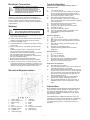
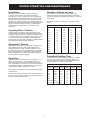
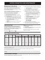
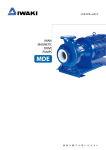
INSTALLATION AND
OPERATING INSTRUCTIONS
CM Series
ISO2858 Heavy Duty
Industrial Centrifugal Pump
Please pass these instructions on to the operator of this equipment.
Introduction
Foundations
This manual contains instruction for installation,
operation and maintenance of ISOspec® CM series
of single stage, non-self priming, centrifugal pumps.
Therefore, please read it carefully before use to obtain a
long satisfying service life of the purchased unit.
Suction Piping
Thank you for purchasing a quality Davey product. It is
our commitment to satisfy our customers by offering our
very best service.
The pump unit should be mounted on a foundation that
is substantial enough to withstand the weight of the unit
& large enough to accommodate all mounting feet so
they can be securely fixed to avoid movement.
Davey ISOspec® CM series centrifugal pumps are
designed with high efficiency and low maintenance
features.
Specifications
Model designation (example) :CM 125×100-200
All fittings & suction piping should be free of air leaks.
Nominal dia. of impeller (mm)
Dia. of outlet (mm)
Dia. of inlet (mm)
Series code of pump
When a suction lift or long suction lengths are
unavoidable, consideration should be given to over
sizing the suction line to reduce suction losses.
On suction lifts a foot valve will be required, sized equal
to the suction line size. For applications on creek beds
or dams, please install a foot valve & strainer, well
submerged below the surface, to reduce whirlpools & air
inclusion. Air inclusion can result in cavitation reducing
the pump performance & eventually destroying the pump
or its components.
Inspection of Pump
Always check on receipt of delivery you have
received the correct pump unit. To identify, see above
specifications and label below. Check correct motor kW
& speed on motor nameplate (attached to motor) prior to
installation.
If bends are required, long radius bends should be used.
To help ensure a less turbulent entry into the pump,
a straight length of pipe should be installed between
any bends and the pump inlet. This straight length
should be at least 2.5 times the pump inlet diameter in
length. Pipework supports should be installed to both
inlet and outlet pipes to ensure that they are supported
independently of the pump flanges.
Discharge Piping
Delivery
Upon receipt the unit should be thoroughly inspected for
any damage sustained during transit. Any equipment
damage or shortfall should be immediately advised to
your nearest Davey office or Davey customer service
centre.
Storage
If the unit is not to be installed immediately, it should be
stored in a clean, dry and preferably warm environment.
Shafts of stored motors should be rotated occasionally.
Specific vibration during storage may lead to “brinelling”
of the bearings, therefore motors that are subject to
extended storage where vibration exists, should be fitted
with bearing locks.
Discharge piping must be selected of a size that would
equal the discharge of the pump. For long discharge
lengths, consideration should be given to using larger
diameter pipework. Larger size pipes have lower
pressure losses for a given flow rate, and may help
reduce the running costs for your pumping system.
Talk to your nearest Davey dealer to calculate all system
losses. To avoid air pockets in discharge lines at high
points, vent cocks may be required to release air blocks
accumulated within the system. Air pockets may affect
the performance of the pump. A throttling valve should
be installed in the discharge line to ensure the pump
works within the performance curve.
Installation Location
It is important to select a site as close to the liquid
source as possible. When a suction lift is unavoidable,
install the pump as near to the water level as possible
(see suction piping). You should always check
the maximum permissible lift of the pump from its
performance curve.
~2~
Electrical Connection
Trouble Shooting
Pump is running but failing to deliver water or
desired pressure.
WARNING: When installing, servicing or
attending pump, always ensure power is
switched off and lead unplugged. Electrical
connections should be serviced only by
qualified persons. If the electrical supply lead
is damaged, it must be replaced.
1)
2)
3)
4)
5)
Ensure all electrical connections are solid and
continuous. Check motor starter and overloads for
correct rating and trip setting. All circuit breakers, HRC
fuses or protective devices associated with the motor
must be rated to suit motor running current and starting
characteristics.
6)
7)
8)
9)
10)
11)
12)
Starting
Caution: Do not attempt to run pump if it
has not been filled with water (primed).
Severe damage will result to shaft seal.
1) Ensure the suction line & pump casing is full of water
open suction valve if fitted.
2) Check power is off & rotate the pump shaft slowly to
release any trapped air within the pump casing.
3) Close the discharge valve.
4) Check the direction of rotation on the pump casing or
motor cover.
5) Prior to initial start up, the following steps must be
taken:
• Insulation resistance test. On machines up to 600
volt, the minimum value should be 1MΩ.
• Thermistors if fitted, should be checked for continuity
with a multimeter and never mega-tested.
• Ensure supply voltage and frequency correspond to
the motor nameplate ratings.
• Ensure shaft turns freely before initial start.
• Measure stator resistance and record in Log Book.
6) If this is correct you may now start the pump, when
it reaches full speed you will see the pressure in the
discharge line rise. Slowly open the discharge valve
until the pump adjusts to maintain its duty point.
Turn the unit off.
Check suction line is free of debris or blockages
& check that the pump has not lost its prime. If
so, remove blockage & repeat Starting at step 1).
Check that the suction valve is open.
Check that the discharge valve is open.
Check for air leaks. These may not always be
visible to the naked eye unless pressure is applied
to the suction line.
Check that the suction line is not too long.
Is suction line to pump excessive?
Is the foot valve stuck open or undersized?
Is speed too slow?
Check motor direction rotation.
Check for possible clogging in impeller vanes
Is the discharge piping undersized for
applications.
Excessive Vibration
1)
Turn the unit off.
2)
Check the motor is rotating in correct direction.
3)
Check both motor feet & pump feet are secured
properly.
4)
Check drive coupling is secured tightly to the
motor shaft.
5)
Check motor bearings are OK.
6)
Impeller could be partially blocked causing
imbalance.
Noisy Operation
1)
Turn the unit off.
2)
Check motor bearings.
3)
Check pump is primed.
4)
Check suction line is not damaged, causing
insufficient supply & resulting in cavitation.
5)
Check you are not pumping solids.
High Power Consumption
1)
Check direction of rotation.
2)
Check operating speed on the motor matches the
intended performance curve speed.
3)
Check that the estimated head is correct, as pump
may be running down on its curve, producing high
flow, but drawing more power. Throttle the pump
back on to its curve via discharge gate valve or
reduce impeller diameter.
4)
The Specific Gravity or Density of the liquid is
greater than 1kg/litre affecting power draw.
5)
Check impeller diameter for the correct size, to
establish maximum power requirement at duty
point.
Structural Representation
Lubrication
Motor bearings are lubricated with lithium based rolling
contact bearing grease, suitable for operation with-in
the cooling air temperature range of -20oC to +55oC.
For operation outside this temperature range, special
lubricants are required.
1.Pump casing
3. Rear casing cover
5. Bell housing
7. Bolt
9. Bolt
11. Bronze wear ring
13. Impeller washer
15. Impeller key
17. Volute drain plug
Special lubricants or additional maintenance may be
required in the case of motors exposed to comparatively
high degrees of pollution, high humidity, increased
or changed bearing loads, or prolonged continuous
operation.
2.Impeller
4. Stub shaft
6. Motor
8. Bolt
10. O-ring
12. Mechanical shaft seal
14. Impeller nut
16. Muff coupling
~3~
MOTOR OPERATION AND MAINTENANCE
Installation
Number of Starts per hour
All motors must be installed in such a manner as
to ensure the air intake is not obstructed. Refer to
dimension “BL” in the cooling section of this catalogue.
Bed plates or slide rails should be firmly fixed to a solid,
level foundation to ensure the motor remains rigid and
vibration free. Shims or packers (if required) must be of
adequate size and placed adjacent to and between base
fixings. Protective transport coatings on shafts and/or
flanges must be removed prior to connection to the
driven load.
The number of starts per hour is dependant on the
inertia of the driven load and the load torque demand.
A guide to generally acceptable starts per hour would be
as per table.
For greater number of starts per hour, please contact
Davey.
Starts per hour
Frame
2 pole
4 pole
6 pole
8 pole
71
- 40- 80
20
40
40
90
16
30
40
100
16
30
40
40
112
16
30
40
40
132 10 2025 25
160
10
20
25
25
180
8
15
20
20
200
6
12
12
12
225 5 1010 10
250
4
8
8
8
280
3
6
6
6
315 3 44 4
Coupling Drive / Service
In fitting couplings or pulleys to the motor shaft, care
must be taken to ensure the roller/ball bearings are not
damaged. Tapped holes are provided in shaft extensions
to assist in the fitment of couplings and/or pulleys. Under
no circumstances should couplings and/or pulleys be
impact driven onto the shaft. Couplings or pulleys should
be independently balanced with a half key.
Alignment / Service
Great care must be taken in aligning the complete unit,
since misalignment can cause rapid deterioration of
bearings and lead to other mechanical failures due to
the stress produced. After final tightening of foundation
bolts, machine alignment should be rechecked as bed
plates could distort. No end thrust should be applied to
the motor without express approval.
Permitted Starting Time
Operation
In respect to the temperature rise of the motor, starting
time (i.e., from rest to operational speed) should not
exceed the time indicated in the following table. Motor
must be allowed to cool prior to each start.
Standard motors are designed for a 415 volt (±5% ) 3
phase, 50 Hertz supply. Use of standard motors on
other supply systems should be verified with our office
prior to installation. All units are S1 rated to AS1359 and
associated standards, for operation below 1000 metres
at a maximum ambient temperature of 40°C.
Maximum starting time (sec)
Starting
Frame Method 2 pole 4 pole 6 pole 8 pole
71
D.O.L.
-
26
-
80
D.O.L.
15
26
40
90 D.O.L.10 15 25 100
D.O.L.
12
13
18
40
112
D.O.L.
10
10
18
35
132D.O.L.
1412 1225
160-355 D.O.L.
15
15
20
20
160-355star-delta 45
45
60
60
For operation in conditions other than that above please
contact Davey.
Electric motor starting imposes severe thermal stress on
the motor, the frequency of starting should be minimized
to ensure optimum machine life.
~4~
MOTOR OPERATION AND MAINTENANCE
Maintenance Instructions
E. On a six (6) monthly basis, in addition to the items in
‘D’ :
i) Check stator resistance (compare to original and
enter in log book)
ii) Check supply voltage at motor terminals.
iii) Check bearings for noise/overheating.
F. On an annual basis, in addition to the items in ‘D’
and ‘E’ : i) Re-grease bearings in line with chart below.
Note: As indicated in the chart, some bearings
may require more frequent grease replacement.
ii) Strip motor down and clean thoroughly.
iii) Check bearings for wear/damage - replace as
necessary.
iv) Check all machine bolts for cracks or damage
- replace as necessary.
v) Check all holding bolts for signs of fatigue/
damage - replace as necessary.
vi) After re-assembly, check and record:
Full Load Current
Full Load Voltages
Full Load Speed
vii) Ensure cooling fan is operational.
G. Ensure plant log book records commissioning data
and compare maintenance data with original.
The following maintenance instructions apply to all SGA
motors except for hazardous location motors. For
SGAE, SGAN and SGAD motors maintenance must
be carried out by an authorized service agent. Contact
CMG for detailed instructions.
To obtain maximum service life from your electric
motor, it is recommended the following maintenance be
implemented and recorded in a plant log book.
A. Ensure air intake space is unobstructed.
B. On a weekly basis use an air hose to ensure all
airways are clear and free of dust.
C. Do not wash the motor down unless it is IP66 rated.
D. On a quarterly basis: i) Check motor terminals for tightness and contact.
ii) If terminal lug/lugs are discolored, re-terminate.
iii) Check operation of starting equipment, ensuring
all terminations are tight.
iv) Check mechanical operation of thermal
overload.
v) Check mechanical operation of thermistor relay
(if fitted).
vi) Check operation of space heaters (if fitted).
Sealed Bearings
Where:
t = Average grease life (hours)
n = Speed (RPM)
N = Bearing limiting speed with grease lubrication (RPM)
T = Operating temperature (°C)
The required replacement interval for sealed bearings
is generally determined by the grease life which is
dependant on operating temperature, operating speed,
the limiting speed of the bearing and the type of grease.
Under normal operating conditions the following
relationship applies:n n
log t = 6.54 – 2.6 – (0.025 – 0.012
T
N
N)
For further information, please contact your nearest
CMG office for advice.
Open (Regreasable) Bearings
Recommended Grease Replenishment Intervals (Hours)1)
Bearing
number
6312/NU312
6313/NU313
6314/NU314
6315/NU315
6316/NU316
6317/NU317
6318/NU318
6319/NU319
6322/NU322
1)
Bearing
bore
[mm]
Qty of
grease
[g]
3000 r/min
1500 r/min
1000 r/min
750 r/min
Ball
Roller
Ball
Roller
Ball
Roller
Ball
Roller
60
65
70
75
80
85
90
95
110
20
25
30
30
35
40
45
45
60
3800
3400
3000
2570
2200
1800
1650
1500
1200
1900
1700
1500
1285
1100
900
825
750
600
10100
9400
8800
8200
7600
7100
6600
5700
4800
5050
4700
4400
4100
3800
3550
3300
2850
2400
16000
15100
14300
13500
12800
12100
11500
9000
8300
8000
7500
7150
6750
6400
6050
5750
4500
4150
20000
20000
19500
18500
17700
16800
16000
14600
13400
10800
10300
9750
9250
8850
8400
8000
7300
6700
Based on maximum grease service life of 20,000 hours.
It should be noted that for motors fitted with Ball and Roller bearings, the lubrication intervals for both bearings should be
based on the roller bearing data.
The re-lubrication intervals recommended are calculated on the basis of normal working conditions.
Note: Air operated grease guns should not be used.
Replenishment of grease media should be by means of a hand held grease gun whilst motor is running with relief plate
removed.
Recommended Lubricant
Use Lithium based grease such as Shell Alvania R3 unless otherwise specified. SGAH, SGASS and SGAHS require
extra high temperature grease, Magnalube G or equivalent.
~5~
Davey® Repair or Replacement Guarantee
In the unlikely event in Australia or New Zealand that this Davey product develops any malfunction
within one year of the date of original purchase due to faulty materials or manufacture, Davey will at
our option repair or replace it for you free of charge, subject to the conditions below.
Should you experience any difficulties with your Davey product, we suggest in the first instance that
you contact the Davey Dealer from which you purchased the Davey product. Alternatively you can
phone our Customer Service line on 1300 367 866 in Australia, or 0800 654 333 in New Zealand, or
send a written letter to Davey at the address listed below. On receipt of your claim, Davey will seek to
resolve your difficulties or, if the product is faulty or defective, advise you on how to have your Davey
product repaired, obtain a replacement or a refund.
Your Davey One Year Guarantee naturally does not cover normal wear or tear, replacement of product
consumables (i.e. mechanical seals, bearings or capacitors), loss or damage resulting from misuse
or negligent handling, improper use for which the product was not designed or advertised, failure to
properly follow the provided installation and operating instructions, failure to carry out maintenance,
corrosive or abrasive water or other liquid, lightning or high voltage spikes, or unauthorized persons
attempting repairs. Where applicable, your Davey product must only be connected to the voltage
shown on the nameplate.
Your Davey One Year Guarantee does not cover freight or any other costs incurred in making a claim.
Please retain your receipt as proof of purchase; you MUST provide evidence of the date of original
purchase when claiming under the Davey One Year Guarantee.
Davey shall not be liable for any loss of profits or any consequential, indirect or special loss, damage or
injury of any kind whatsoever arising directly or indirectly from Davey products. This limitation does not
apply to any liability of Davey for failure to comply with a consumer guarantee applicable to your Davey
product under the Australian or New Zealand legislation and does not affect any rights or remedies that
may be available to you under the Australian or New Zealand Consumer Legislation.
In Australia, you are entitled to a replacement or refund for a major failure and for compensation for
any other reasonably foreseeable loss or damage. You are also entitled to have the goods repaired or
replaced if the goods fail to be of acceptable quality and the failure does not amount to a major failure.
Should your Davey product require repair or service after the guarantee period; contact your nearest
Davey Dealer or phone the Davey Customer Service Centre on the number listed below.
For a complete list of Davey Dealers visit our website (davey.com.au) or call:
AUSTRALIA
NEW ZEALAND
Customer Service Centre
6 Lakeview Drive,
Scoresby, Australia 3179
Ph:
1300 367 866
Fax:
1300 369 119
Website:davey.com.au
Customer Service Centre
7 Rockridge Avenue,
Penrose, Auckland 1061
Ph:
0800 654 333
Fax:
09 527 7654
Website:daveynz.co.nz
Davey Water Products Pty Ltd
Member of the GUD Group
ABN 18 066 327 517
® Davey & ISOspec are registered trade marks of Davey Water Products Pty Ltd.
© Davey Water Products Pty Ltd 2011.
P/N 49720-6 supersedes P/N 49720-5
* Installation and operating instructions are included with the product when purchased new.
They may also be found on our website.