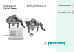
1
Operating Instructions EDm Motor Drive
(to use with DYNA Z Pull-Off and Extraction Tester)
PROCEQ SA
Ringstrasse 2
Postfach 336
CH-8603 Schwerzenbach
Switzerland
Tel:
Fax:
E-mail:
Internet:
+41 (0)43 355 38 00
+41 (0)43 355 38 12
[email protected]
www.proceq.com
Subject to change without notice
Copyright © 2004 by PROCEQ SA Schwerzenbach
2004 07 225-6 E
Page 2
Contents
1
1.1
1.2
1.3
1.3.1
1.3.2
1.3.3
1.4
1.5
Safety
General Instructions
Liability
Safety Instructions
General
Unauthorized Operators
Safety Symbols
Correct Use
Reference Standards and Regulations
4
4
4
4
4
4
5
5
5
2
2.1
2.2
2.3
2.4
Product Description
Applications
EDm Motor Drive: Controls
Technical Data
Power Supply
6
6
6
7
7
3
Installation Guide
7
4
4.1
4.2
4.2.1
4.2.2
4.2.3
4.2.4
4.3
Settings
Direction of Rotation
Setting the Loading rate increase
DYNA Z16, Z16E Pull-Off Tester
DYNA Z16S, Z16SE, Z16Fs Extraction Tester
DYNA Z6, Z6S, Z6SE Pull-Off / Extraction Tester
Accuracy
Operating Limits
Copyright © 2004 by PROCEQ SA Schwerzenbach
8
8
8
9
10
11
12
12
5
5.1
5.2
5.3
5.4
Measurements
13
Measurement Process with DYNA Z and EDm Motor
13
Drive
Battery Charge State Indicator
14
14
Typical Loading rate increase Curve
Overheating
14
6
6.1
6.1.1
6.1.2
6.1.3
6.2
6.2.1
6.2.2
6.3
6.3.1
6.3.2
Power Supplies
EDm BC Battery Holder
Connecting the EDm BC Battery Holder
Operating Time
Changing the Batteries
EGS 1800 Power Supply
Connecting the EGS 1800 Power Supply
Operating Time
Laboratory Power Supply / Mains Power Supply
Connecting any other Power Supply
Operating Time
15
15
16
16
16
17
17
17
18
18
18
7
7.1
Maintenance
Storage
19
19
8
8.1
8.1.1
8.2
8.3
8.4
Data
Form of Supply
EDm Motor Drive with EDm BC Battery Holder
Accessories
Calibration
Individual Setting Curves
19
19
19
20
21
21
2004 07 225-6 E
Page 3
1 Safety
1.1 General Instructions
1.3 Safety Instructions
Please read these operating instructions prior to
placing in operation for the first time. They contain
important instructions on the safety, use and
maintenance of the EDm motor drive and the related
components.
1.3.1 General
1.2 Liability
Our "General Terms and Conditions of Sales and
Delivery” always apply. Warranty and liability claims
for injuries and damage to property are excluded if
they result from one or more of the following causes:
- Incorrect use of the EDm motor drive and the
related components
- Improper use of functions, operation or
maintenance of the EDm motor drive and the
related components
- Failure to observe the instructions in the operating
instructions in relation to the use of functions,
operation and maintenance of the EDm motor
drive and the related components
- Unauthorised modifications to the EDm motor
drive and the related components
- Disasters caused by the action of foreign bodies,
accidents, vandalism and acts of God
Copyright © 2004 by PROCEQ SA Schwerzenbach
-
Carry out the stipulated maintenance properly and
at the correct time.
Following completion of the maintenance tasks,
perform a functional check
(see 7 Maintenance and 3 Placing in Operation).
1.3.2 Unauthorized Operators
Children and persons under the influence of alcohol,
drugs or medication are not allowed to operate the
EDm motor drive and the related components.
Persons who are not familiar with the operating
instructions are only allowed to operate the motor
drive under the supervision of a person familiar with
the device.
2004 07 225-6 E
Page 4
1.3.3 Safety Symbols
The following symbols are given with all important
safety instructions in these operating instructions.
Danger!
This instruction provides information on a
risk of injury and/or serious injury if specific
rules of conduct are not observed.
Attention!
This instruction warns you about equipment
and material damage as well as possible
financial and legal implications (e.g. loss of
guarantee, potential liability, etc.).
Here you will find important instructions
and information
Attention!
The motor drive and the related
components are not water-proof. Do not
use under water. If devices are wet by
water spray, wipe dry immediately.
1.5 Reference Standards and Regulations
ASTM D 4541-02, 2002
DIN EN 24624, 1992
DIN EN 1348, 1999
DIN EN 1542, 1998
PrEN 12504-3, in preparation
ASTM C90-01
DIN 1048, 1991
ZTV-SIB 90, Annex 2
DIN EN 1015-12
1.4 Correct Use
The motor drive is an electromechanical device and is
used for driving the DYNA Z pull-off and extraction
testers. Using this device a continuous increase in
load as per the standards can be generated.
Copyright © 2004 by PROCEQ SA Schwerzenbach
2004 07 225-6 E
Page 5
2 Product Descriptions
2.1 Applications
2.2 EDm Motor Drive: Controls
1
2
4
The EDm motor drive for a DYNA Z pull-off or
extraction tester can be used if a continuous increase
in load is required (e.g. due to requirements in the
applicable standards). The motor drive is used for
operating the hydraulic pump instead of the hand
crank supplied with the DYNA Z testers.
Compared to the hand crank, the drive has the
advantage that a specific rate of increase in the load
can be achieved.
For information on the operation of the DYNA Z …
and DYNA Z …S pull-off and extraction testers,
please refer to the operating instructions for these
devices.
65
3
1 Drive socket with 10x10 internal square drive
2 ON button
3 Voltage regulator (2.4-12 VDC)
4 Connector (supply max. 15 VDC)
5 Battery charge state indicator
6 Switch forward - backward
Fig. 2.01 EDm motor drive
Copyright © 2004 by PROCEQ SA Schwerzenbach
2004 07 225-6 E
Page 6
The motor drive must be operated with DC, the
maximum voltage is 15 VDC.
2.3 Technical Data
Supply:
Voltage at the motor:
Speed:
Torque:
Current consumption:
Battery charge:
state indicator:
Direction of rotation:
On button:
Dimensions:
[mm]
max. 15 VDC only DC, no AC
2.4 to 12 VDC
2.0 to 11.7 rpm
max. 3 Nm
max. 690 mA at full load
LED illuminates at 8.5 VDC and above
- forward, speed and loading rate
increase as per voltage setting (3)
- backward, always at full speed
when not operated, OFF
housing Ø61 +/-1 x 202.5
245 (incl. drive socket and rotary knob)
Drive socket outside Ø14 x 30
Inside 10 x 10
2.4 Power Supply
The EDm motor drive is supplied using an external
power supply (for details see 6 Power supplies) that is
connected to the drive using a connecting cable.
Copyright © 2004 by PROCEQ SA Schwerzenbach
Attention!
If the motor drive is operated with more
than 15 VDC or AC, damage to the
electronics is to be expected.
3 Installation Guide
1
2
3
4
Read the operating instructions carefully
Connect power supply, max. 15 VDC (see 6
Power supplies)
Set direction of rotation (see 4.1 Direction of
rotation) forward → clockwise,
backward ← anti-clockwise
Perform function test – forward with various
voltage settings (speeds) and backward (motor
always runs at full speed). (To switch on press the
ON button (2))
2004 07 225-6 E
Page 7
4 Settings
6
4
3
For the EDm motor drive, the loading rate increase
can be adjusted using the voltage regulator (3) (The
speed of the drive socket is proportional to the
voltage).
4.1 Direction of Rotation
The direction of rotation can be set using the switch
(6) (observe arrow symbols).
Forward (measuring) corresponds to clockwise
rotation (switch (6) up). The voltage at the motor is
only reduced to the voltage set at the rotary knob (3)
when the switch (6) is in this position.
Backward (place pump in initial position) corresponds
to anticlockwise rotation (switch (6) down). In this
switch position the drive always rotates at full speed.
4.2 Setting the Loading rate increase
The required loading rate increase can be adjusted by
means of the voltage regulator (3). The adjusted
voltage (from 2.4 V to 12 V) corresponds to the
voltage at the motor operating in forward mode,
(clockwise).
Copyright © 2004 by PROCEQ SA Schwerzenbach
5
Fig. 4.01 Front plate of EDm motor drive
2004 07 225-6 E
Page 8
For each type of DYNA Z tester, the ratio between the loading rate increase and the regulated voltage is different.
In the following are settings for DYNA Z.. and DYNA Z…E pull-off testers, as well as DYNA Z..S, DYNA Z..SE and
DYNA Z...Fs extraction testers.
4.2.1 DYNA Z16 Pull-Off Tester
Formula:
Loading rate increase vs voltage
DYNA Z16 , Z16E Pull-Off tester
v = 43.0*U – 48.7
500
v=
Rate of force increase [N/s]
450
Loading rate increase [N/s]
U = Regulated voltage [VDC]
400
350
Accuracy:
300
250
200
v of load increase
150
lower limit
100
upper limit
0
3
4
5
6
7
8
9
10
11
± 10%
2.3 to 6 VDC:
± 21 N/s
Example:
For
v=
Set
U=
50
2
6 to 12 VDC:
150 N/s
4.6 VDC
12
Regulated voltage [V]
Fig. 4.02 Voltage setting for DYNA Z16, Z16E Pull-Off Tester
Copyright © 2004 by PROCEQ SA Schwerzenbach
2004 07 225-6 E
Page 9
4.2.2 DYNA Z16S, Z16SE, Z16Fs Extraction Tester
Formula:
Load rate increase vs voltage
Rate of force increase [N/s]
DYNA Z16S, Z16SE, Z16Fs Extraction Tester
800
750
700
650
600
550
500
450
400
350
300
250
200
150
100
50
0
v = 70.1*U – 107.0
v=
Loading rate increase [N/s]
U = Regulated voltage [VDC]
Accuracy:
6 to 12 VDC:
± 10%
2.3 to 6 VDC:
± 32 N/s
v of load increase
Example:
For
v=
Set
U=
lower limit
upper limit
2
3
4
5
6
7
8
9
10
11
300 N/s
5.8 VDC
12
Regulated voltage (V)
Fig. 4.03 Voltage setting for DYNA Z16S, Z16SE, Z16Fs
Extraction Tester
Copyright © 2004 by PROCEQ SA Schwerzenbach
2004 07 225-6 E
Page 10
4.2.3
DYNA Z6, Z6E, Z6S, Z6SE Pull-Off and Extraction Tester
Formula:
Load rate increase vs voltage
DYNA Z6, Z6E, Z6S, Z6SE
Pull-Off / Extraction Tester
v = 40.0*U – 49.9
550
v=
500
U = Regulated voltage [VDC]
450
Rate of force increase [N/s]
Loading rate increase [N/s]
400
Accuracy:
350
2.3 to 12 VDC:
300
± 25%
250
Example:
For
v=
Set
U=
200
150
v of load increase
100
lower limit
50
upper limit
250 N/s
7.5 VDC
0
2
3
4
5
6
7
8
9
10
11
12
Regulated voltage [V]
Fig. 4.04 Voltage setting for DYNA Z6, Z6E, Z6S, Z6SE
Pull-Off and Extraction Tester
Copyright © 2004 by PROCEQ SA Schwerzenbach
2004 07 225-6 E
Page 11
4.2.4 Accuracy
Measurement accuracy space is influenced by two
factors:
• EDm motor drive in combination with the
individual DYNA Z-instrument as shown in the
figures 4.02, 4.03 and 4.04
• Manual voltage setting of ± 0.3V
The combination of the EDm motor drive with the
DYNA Z causes the lower accuracy, thus especially
for the DYNA Z testers with a nominal load of 6 kN
(see figure 4.04).
If a higher accuracy is required, we recommend
plotting a test curve using WIGAonline software (see
8.2 Accessories) that will plot the gradient for the
loading rate increase (see 8.4 Individual setting
curve). In this way the rate can be set exactly as the
repetition accuracy (combination DYNA Z tester and
EDm motor drive) is good to max. 5%.
If a DYNA Z tester to be used after a long
period without use, the device must be
loaded once to nominal load and then
unloaded. Only then the repetition
accuracy is as described above. This step
is recommended each time prior to placing
the tester in operation.
Copyright © 2004 by PROCEQ SA Schwerzenbach
4.3 Operating Limits
The voltage regulator keeps the voltage constant at
the value set (between 2.4 and 12 V) on condition
that the supplied voltage is at least 0.3 V higher as
the voltage to be set, due to the voltage drop in the
voltage regulator of approx. 0.3 V.
For usual tests, with lower rates of load increase as
the one mentioned in 5.2 Battery Charge State
Indicator and with the LED (5) on, the loading rate
increase is kept at the value set.
In case of unusual tests with a higher
loading rate increase as the one
mentioned in 5.2 Battery Charge State
Indicator, new batteries should be used
and the effective battery voltage must be
measured. During the whole test, the
effective voltage must be at least 0.3 Volt
higher as the voltage set with the
regulator.
2004 07 225-6 E
Page 12
5 Measuring
5.1 Measurement Process with DYNA Z
and EDm Motor Drive
1
2
3
4
Measurement process (incl. preparation of probe)
as described in the operating instructions for the
DYNA Z pull-off / extraction tester.
Prepare the EDm motor drive (see 3 Placing in
operation as well as 4.2.5 Accuracy / note).
Set required loading rate increase as per formula
or diagram (see 4.2 Setting the Loading rate
increase) using voltage setting (3).
Fit EDm motor drive to 10x10 square drive
instead of hand crank.
Hold drive firmly and switch on by pressing the
On button (2). Keep On button (2) pressed until
the sample fractures or until the required load or
nominal load of the tester is reached.
Attention!
The EDm motor drive and the DYNA Z
tester do not have overload protection!
The EDm motor drive is primarily designed for the
DYNA Z6 and Z16 testers. With these testers it is
possible to apply the EDm motor drive up to the
nominal load without problems.
DYNA Z
square end
button 2
Drive EDm
Attention!
Do not load the DYNA Z tester beyond
the nominal load (brief overload of 10%
is allowed)
5
When the pump stop is reached (whether forward
or backward), immediately switch off drive by
releasing the On button (2).
Copyright © 2004 by PROCEQ SA Schwerzenbach
Batterieholder EDm BC
Fig. 5.01 Measurement with DYNA Z and EDm
motor drive
2004 07 225-6 E
Page 13
5.2 Battery Charge State Indicator
If the LED goes out (i.e. the supply voltage is less
than 8.5 V) the batteries should be replaced or the
power supply charged.
5.3 Typical Loading rate increase Curve
The increase in the load is not linear at the start as
first all the play and static friction must be overcome.
The gradient of the linear curve is the loading rate
increase v. In the example of figure 5.02, with
F = 0.3082*t – 18.82 = v*t – 18.82, the loading rate
increase becomes
v = F/t = 0.3082 kN/s = 308.2 N/s.
F = Load [kN]
t = Time [s]
v = Loading rate increase [kN/s]
Copyright © 2004 by PROCEQ SA Schwerzenbach
Typical rate of force increase
DYNA Z16 pull-off tester
16
14
12
F o rc e [k N ]
The green light emitting diode (5) illuminates when
the motor is rotating (ON button (2) pressed) and the
supply voltage is more than 8.5 V. This corresponds
to a loading rate increase of around:
320 N/s for DYNA Z16, Z16E
490 N/s for DYNA Z16S, Z16SE, Z16Fs
290 N/s for DYNA Z6S, Z6E, Z6S, Z6SE
10
8
6
F = 0.3082*t - 18.82
4
Force curve
Force linearised
2
0
0
20
40
60
80
100
120
Time [s]
Fig. 5.02 Typical Curve of load increase
5.3 Overheating
For lower rates of load increase, i.e. voltages between
2.3 and 4 V, the temperature increase inside the motor
may be up to 40 degrees Celsius due to the necessary
throttling of the EDm motor drive.
To avoid overheating of the EDm motor
drive, do not operate the motor in this
throttling mode (2.3 V to 4 V) if outside
temperature exceeds 40 degrees Celsius.
2004 07 225-6 E
Page 14
8
7
6 Power Supplies
Attention!
The EDm motor drive is only allowed to be
supplied with DC to maximum 15 VDC.
The EDm motor drive can in principle be supplied in
three ways:
-
Batteries
Power supply or
Special supply unit
6.1 EDm BC Battery Holder
The EDm BC battery holder supplies the EDm motor
drive using eight 1.5 V batteries that, connected in
series, produce 12 VDC.
The battery holder is not suitable for the
use of rechargeable batteries as when
fully charged these only produce 1.2 V
each and thus only yield a supply voltage
of 9.6 VDC instead of 12 VDC.
13
11
9
10
9
7
8
9
10
11
Knurled nut
Baby cells type C voltage 1.5 VDC (LR14)
Foot
Transparent housing sleeve
Device connector, 2-pin
(miniature round connector, series 680)
12 Connecting cable (see 6.2
EGS 1800 power supply and 8.2 Accessories)
13 Carry strap
Fig. 6.01 EDm BC Battery holder
Copyright © 2004 by PROCEQ SA Schwerzenbach
2004 07 225-6 E
Page 15
6.1.1 Connecting the EDm BC Battery Holder
Connect the battery cable (12) to the connectors on
the EDm BC battery holder and EDm motor drive. The
battery holder and the motor drive have the same
threaded connector (see point 11 Section 6.1 or point
4 Section 4). When making the connections ensure
that the groove on the socket is aligned with the lug
on the plug.
6.1.2 Operating Time
3
Replace batteries (8).
Attention!
Ensure that the polarity is correct.
4
5
6
Slide entire battery block into the housing sleeve
(10).
Fit rear cover with rear foot (9) to threaded rods.
Tighten the two knurled nuts (7) (before tightening
place the battery holder on a flat surface on its
feet so that the feet are correctly aligned).
The EDm motor drive can be operated for approx. 25
hours with batteries of type C (Baby).
Exact information on the operating time is not possible
as the operating time is heavily dependent on the
current supplied to the motor, which in turn can vary
significantly depending on the load.
6.1.3 Changing the Batteries
1
2
Undo the two knurled nuts (7).
Pull battery block cover incl. foot (9),
device connector (11) and batteries (8) from the
housing sleeve(10).
Copyright © 2004 by PROCEQ SA Schwerzenbach
2004 07 225-6 E
Page 16
6.2 EGS 1800 Power Supply
6.2.1 Connecting the EGS 1800 Power Supply
PROCEQ also supplies the EGS 1800 power supply
from Einhell. To connect the power station to the EDm
motor drive you will need in addition to the normal
connecting cable (12), an adapter cable (14).
The adapter cable (14) (for picture also see 8.2
Accessories) provides the appropriate connection
between the EGS 1800 power supply and the
connecting cable. One end of the adapter cable is to
be connected to the threaded connector on the
connecting cable (ensure that the groove on the
socket is aligned with the lug on the plug) and the
other end to the "cigarette lighter connector" on the
EGS 1800. Using this cable the motor drive can also
be connected to the cigarette lighter connector in a
car.
Refer to the separate operating instructions for
information on the operation of the EGS 1800 power
supply.
6.2.2 Operating Time
Using the EGS 1800 power supply the operating time
is approx. 36 hours.
Exact information on the operating time is not
possible as the operating time is heavily dependent
on the current supplied to the motor, which in turn can
vary significantly depending on the load.
12
14
Fig. 6.02 Power supply EGS 1800
Copyright © 2004 by PROCEQ SA Schwerzenbach
2004 07 225-6 E
Page 17
6.3 Laboratory Power Supply / Mains Power
Supply
If the motor drive is to be operated from a laboratory
power supply / mains power supply, we recommend
the use of a linear power supply, as otherwise
measurement interference may result.
6.3.1 Connecting any other Power Supply
To connect other power supplies, special connecting
cables or adapters are required that are not
standardised. PROCEQ can provide assistance in
finding a specific solution.
6.3.2 Operating Time
To connect a laboratory power supply / mains power
supply, a special connecting cable is required.
As long as the power supply is switched on or if it has
capacitance, the drive can be operated.
If a switched laboratory power supply is
used, interference may be produced that
will cause measuring errors.
Attention!
When power supplies are used, ensure that
the voltage is set to maximum 15 VDC and
that the EDm motor drive is never supplied
with AC.
Standard power supplies often have a
high internal resistance. When the EDm
motor drive is supplied, considerable
current (up to 460 mA) is drawn that can
result in a significant voltage drop.
Copyright © 2004 by PROCEQ SA Schwerzenbach
2004 07 225-6 E
Page 18
7 Maintenance
In principle the components used in the EDm motor
drive and the EDm BC battery holder are
maintenance-free. In case of soiling, please clean.
8 Data
8.1 Form of Supply
8.1.1 EDm Motor Drive with EDm BC Battery
Holder
Attention!
When cleaning, please do not hold the
device under running liquid or immerse it in
a liquid, as the EDm motor drive and its
accessories are not water-proof. Do not use
abrasive cleaning agents.
A moist cloth or a cloth soaked in alcohol can be used
for cleaning.
Danger!
Undo all cable connections prior to
cleaning.
7.1 Storage
All components are to be stored in a dry place, if
possible free of dust.
If the device is not to be used for an extended period,
the batteries are to be removed from the EDm BC
battery holder.
Copyright © 2004 by PROCEQ SA Schwerzenbach
- EDm motor drive
- EDm BC battery holder
- Connecting cable
- Carry strap
Item no. 345 09 220
Fig. 8.01 EDm motor drive with EDm BC battery
holder
2004 07 225-6 E
Page 19
8.2 Accessories
Connecting cable
EDm / EDm BC
item no. 345 09 226
EDm motor drive
with drive socket
item no. 345 09 223
Adapter cable
for EGS 1800
item no. 345 09 227
EDm BC
battery holder
with carry strap
item no. 345 09 224
Drive socket
for EDm motor drive
item no. 345 09 228
.
EGS 1800
power station
without adapter cable
item no. 345 09 225
Carry strap
for EDm BC
item no. 345 09 229
EGS 1800
power station
with adapter cable
item no. 345 09 221
WIGAonline software
item no. 380 01 243
Typischer Kraftanstiegsverlauf
DYNA Haftprüfgerät Z16
16
14
Kraft [kN]
12
10
8
F = 0.3082*t - 18.82
6
4
Kraftverlauf
Kraft linearisiert
2
Fig. 8.02 to Fig. 8.09 Accessories
Copyright © 2004 by PROCEQ SA Schwerzenbach
0
0
20
40
60
80
100
120
Zeit [s]
2004 07 225-6 E
Page 20
8.3 Calibration
The EDm motor drive can be calibrated together with
a DYNA Z pull-off or extraction tester by a PROCEQcertified service centre.
The device should be calibrated once a
year.
8.4 Individual Setting Curves
For each combination of EDm motor drive with
DYNA Z instrument, an individual setting curve can be
determined. With this, the accuracy of the speed
setting for the load increase can be improved (see
4.2.4 accuracy).
The measured values of loading rate increase in N/s
vs voltage in V can be entered into an Excel sheet.
The setting curve can then be determined using the
feature of the trend curve in Excel as follows:
•
Mark the pair of values in the Excel sheet
•
Click the cursor on the icon “curve” and then right
click the mouse
•
Add trend curve, linear option and show equation
in the figure
•
Take the loading rate increase from the equation
The curve must be determined using at least four
points. For this, we recommend setting the voltage on
the EDm motor drive to 2.4 V, 5 V, 8 V and 12 V. For
each voltage a test must be performed to get the
typical curve of load increase (with WIGAonline
software or manually with the stop watch) and to
determine the speed in N/s of the linear portion of the
curve (see 5.3 Typical Loading rate increase Curve).
The linear portion of the curve is approximately
between 4 to 6 kN for DYNA Z instruments with 6 kN
nominal load and approximately between 9 to 16 kN
for DYNA Z instruments with 16 kN nominal load.
Copyright © 2004 by PROCEQ SA Schwerzenbach
2004 07 225-6 E
Page 21