1
A+ ciao installation
technology with style
and operating
Instructions
K508L
wallmount
rangenooa
=
не м site
= НО ras
DESCRIPTION
The hood may be in the filtering or the ducting version.
Filtering version: the hood aspirates the kitchen air saturated with fumes and odours, purifies it through the grease
filters and charcoal filter and returns clean air into the room. For constant efficiency, the charcoal filter must be replaced
periodically; the charcoal filter is not supplied. |
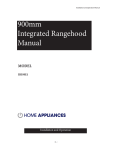
If your extractor hood is the filter version, bear in mind that:
- if wall-mounted units are installed at the sides of the extractor hood, so that the slots on the hood may be obstructed
(Fig. 1), procure a rigid hose (T) fitted with a 45° coupling at the top end; the tube is not supplied. In this case, the
extractor hood should be installed before fittine the wall-mounted units and, when installation is complete, the upper
part of the hood must not be obstructed by the ceiling, the wall-mounted units or other items.
- if, on the other hand, the slots on the hood are not obstructed by wall-mounted units (Fig. 2), a baffle (A) and a flange
(B) are required; the baffle and flange are NOT supplied: order them from your retailer.
Ducting version (Fig. 3): the hood aspirates the kitchen air saturated with fumes and odours, passes it through the
grease filters and expels it to the outside through an outlet pipe. With this version the charcoal filter is not required. Decide
from the outset on the type of installation (filtering or ducting). For greater efficiency, we recommend you install the hood
in the ducting version (if possible).
INSTALLATION
ATTENTION: Two persons are required for proper installation; the unit should be installed by a qualified operator.
INSTALLATIONINDUCTING VERSION:
Before fixing, the outlet pipe for air evacuation to the outside must be installed. Use an outlet pipe with: — minimum
indispensable length; -minimum possible bends (maximum angle of bend: 90°); —certified material {according to the State);
~ an as smooth as possible inside. It is also advisable to avoid any drastic changes in pipe cross-section (recommended
diameter: 150 mm). For airevacuation to the outside, follow all the other instructions given on the “Warnings” sheet. Prepare
the power supply within the telescopic chimney (for the electrical connection, follow all the other instructions on the
“Warnings” sheet).
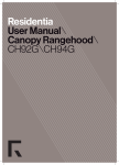
1. Turn the upper telescopic flue around so that the slots face downwards (Fig. 4).
2. Install the flange in the device air outlet and press slightly (Fig. 5). Connect a flex pipe to the air outlet mouth of
the extractor hood and secure it with a metal retainer clamp (the pipe and band are not supphed) - Fig. 5.
3. Drawaline on the wall in vertical line with your hob. Mark the 4 holes to be drilled in the wall, respecting the distances
indicated in Fig. 6. Drill the holes and fit the screw anchors provided. As already specified on the “Warnings” sheet, bear
in mind that the distance between the lower edge of the hood and the hob must be min. 650 mm. Fix the metal bracket
(A) to the wall using 2 holes {B) just drilled (Fig. 7); the screws for fixing the bracket are provided. Use the 2 cut-out triangles
on the bracket to position it exactly along the vertical axis of the hood. |
4. Hang the hood on the bracket (Fig. 8). Adjust the horizontal position moving the hood to the right or left so that it
is aligned with the wall units. Fix the hood with 2 screws (C).
5 Secure the bracket to the ceiling or the wall so that it is aligned with your extractor hood (Fig. 9).
6. Connect the flex pipe to the air evacuation hole in the wall (Fig. 10).
7. Make the electrical connection of the hood by means of the power cable (Fig. 10).
8. Raise the upper flue as far as the ceiling and secure it with two screws - Fig. 11.
INSTALLATIONINFILTERING VERSION:
Slide out the upper flue and position it with the slots upwards (Fig. 12).
- Fit the adapter flange on to the baffle (Fig. 13) and then connect a flex tube, securing it with a metallic clamp band
{the tube and band are not supplied). Secure the baffle to the upper flue with 4 screws (Fig. 14).
--Refit the upper flue complete with baffle and pipe (Fig. 15).
- Connect the flex tube to the air outlet mouth of the extractor hood and secure it with a metal retainer clamp (the .
tube and clamp are not supplied).
If the slots on the hood are obstructed by wall-mounted units (Fig. 1}. proceed as follows:
- Connect a rigid tube (T) to the air outlet coupling of the hood; this pipe must be fitted with a 45° coupling at the top
end; the pipe is not supplied. ATTENTION: In this case, the hood should be installed before fitting the wall-mounted
units and, when installation is complete, the upper part of the hood must not be obstructed by the ceiling, the wall-
mounted units or other items.
1. Set the electrical connections inside the decorative pipe (for electrical connections, follow all the other indications
provided in the “Warnings” sheet).
2. Draw a line on the wall in vertical line with your hob. Mark the 4 holes to be drilled in the wall, respecting the distances
indicated in Fig. 6. Drill the holes and fit the screw anchors provided. As already specified on the “Warnings” sheet, bear
in mind that the distance between the lower edge of the hood and the hob must be min. 650 mm. Fix the metal bracket
(A) to the wall using 2 holes (B) just drilled (Fig. 7); the screws for fixing the bracket are provided. Use the 2 cut-out triangles
2 : с B_105
on the bracket to position it exactly along the vertical axis of the hood.
3. Hang the hood on the bracket (Fig. 8). Adjust the horizontal position moving the hood to the right or left so that it
is aligned with the wall units. Fix the hood with 2 screws (C). |
Secure the bracket to the ceiling or the wall so that it is aligned with your extractor hood (Fig. 9).
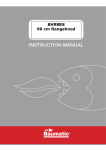
5. Make the electrical connection of the hood by means of the power cable (Fig. 16).
6. Raise the upper flue as far as the ceiling and secure it with 2 screws (Fig. 11).
7
Install the charcoal filter by sliding the 2 filter tangs into the specific seat (Fig. 17) and then rotating It upwards.
>
OPERATION
Depending on the model, the unit is equipped with the following controls:
CONTROLS shownin Fig. 18:
Key A: Turns the LIGHTS off
Kev B : Turns the LIGHTS on. |
Key C : reduces the motor speed until reaching minimum. if pressed for about 27, it stops the motor and storse the
speed.
oy D : drives the motor (calling the last speed used) and increases the speed until reaching maximum.
L Display: |
- signals the running speed.
- signals the filter alarm (with motor off} by displaying the central segment for 30".
- signals Timer activation with a flashing number.
Key E : activates the TIMER (when the motor is running}, so that the hood stops automatically after 5. Also Zero-
sets hour metering when the Filter Alarm is active {motor OFF).
FILTER ALARM: Displayed for 30" when the motor is off:
After 30h of operation, the central segment lights up on the display; ltindicates that the grease filters needto be cleaned.
After 120h of operation, the central segment flashes on the display; ltindicates thatthe grease filters needto be cleaned
and the charcoal filters replaced.
After cleaning the grease filters (and/or replacing the charcoal filters), restart the hour counter (RESET) by pressing
the key E during display of the filter alarm.
_ CONTROLS shownin Fig. 19:
7 À : Light switch.
Кеу В : Моюг ON/OFF switch - speed |
Key CG : Switch - speed ll
Key_D : Switch - speed ili
E : Motor on light.
Grease filters : pay special attention to the grease filters, that must be cleaned at regular intervals.
Remove the grease filters as follows, depending on the model.
Model shown in Figure 20: remove the metal panel by pressing at the points indicated by the arrows; then rotate the
panel so that the right-hand pin slips out of its seat (A); move the panel to the right until the left-hand pin slips out
of its seat. Then remove the grease filter (Fig. 21): press the retainer near the handie inwards and then pull the filter
downwards. Wash the metal panel and the grease filter with neutral detergent.
Model shown in Figure 22: press the retainer near the handle inwards and then pull the filters downwards.
If the model you have purchased has the controls shown in Figure 18, clean the grease filters when the Filter Alarm
appears (see “Controls” paragraph). If the model you have purchased has the controls shown in Figure 19, clean the
grease filters on average every 2 months depending on use.
— Charcoal filters: using the appliance as a filtering version requires the replacement ofthecharcoal filters at regular
intervals.
Disassembly of the charcoal filter: remove the grease filters and/or the metal panel (see explanations above - “Grease
filters” paragraph). Remove the charcoal filter by pressing the retainer inwards and rotating the filter until the two tangs
come out of their seats (Fig.17).
If the model you have purchased has the conirols shown in Figure 18, replace the charcoal filters when the Filter Alarm
appears (see “Controls” paragraph). If the model you have purchased has the controls shown in Figure 19, replace
the charcoal filters on average every 6 months depending on use. |
Lighting: to change the halogen bulbs open the cover levering from the proper slots (Fig. 23). Replace with bulbs
of the same type. CAUTION: Do not handle glass bulb with bare hands. If, after replacing the halogen lights, these
fail to work, allow the appliance to cool and then interrupt power for a few seconds. |
В 105 | - 3
mo Wl Re i i gy а -
“a
e
E...
an
17
i
“ji
|
i
1
i
1
a
i
Ё
i
i
i
:
nera
TA
e 5
(CE EEE EU a EEE EE ee N
de
- =
E ES
LES =.
T aries mr
gh
En
To
Pa
м
А
5 do
de К: x
x vel 2 : 3
EN
с
rame
fi Er
ferns retro
pe
Pa ДоОНКо
fe a han
Hn es
+ A
:
18
вый ek dell ey By
am “eue
ho 7
A e an y a ET
TT
о
AL AT nice
re a
EUA ENTE ЕЯ,
TENE
: AT
55 £2
: Gan
М
Ls
о
о
Ce!
A
Pi
tes E
SE
ai
FLL
at
A
SU
na
Rd
e
a 0
- + EEE EEE RARE y E :
” . pe a eee
E CT
a О
- " AN EN :
” E i
rc
pe 5
7 Вой о
Fa р E, pe i ль Чи
Kd a on >
pacte Lie 7
a...
SE ER a
B_105 | 19
En
ser
rahe
va
E
A
e. За AR
SRE
x
м
Ея
Я
A
de
ut
=
Far
A SE
sen
ER fers TE
a, i!
+ т Ei SH Te
E
o
e
a
nd
CR
a
ro
cu
Rnb eR
a Ta К
o
A
o
pe
Но
Cea
Faas!
Lin
Е
ra
e
rr
or
fos
Pe
os
nt
e
te
E
E
E,
ут
ых
aa!
re CCE
a
E
a
A
Shan
Ze
or]
o
La
ar
Fe
ene
Fen
a
pa HEL А (aaa Ea e
CE e a Sa =
reir =
ete 3
nt arr КЕ
y Es pe
En ace
Career
SE
О
НН
Fe
НЧ me
pa
E
я В
te. e
: AN
` BY ES dee E E =
po
Ня
y
trs
Fee
=
TA
CASA К КК,
E Ы FF nr hy ht
"a COCOA EOC A AAA, AA RS
a A Ta PUC
A fut +
TS TS CET FL
CALL a A LA
ALT
Li ATA TA TA TETA TA TA Ta ATTE,
UTA TT
A TT Te тат.
Тат COMODO
TT
A ELLA ТАЯТ
UTA A
Aw Ld Тя =
T, я
Tr
"ETAPA TT E
rp LS nn
ARAN AAAS ARN
Ng oY
МЕ ГДК №
Fu TLR РЯ,
a
. AL аЬ
JOEL PTE LE LE
tPA SAT TAAL
LAA TAA A
LA LA A EP
FAT? UE,
. ll
"EE
я Ат АЯ РИ
AAC
N
<a
Prin
ia Les
A ES
RL od
a
Sins
he Si
ESE e
E uno
a = i 2
Craig
“ e
ra
Ма
Fed