1
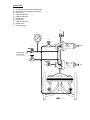
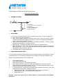
Surge Anticipation & Relief Valve with Dorot 66-300 Pilots
OPERATING INSTRUCTIONS
1. ASSEMBLY SCHEME
A
B
C
P
Main
D
F
E
A.
B.
C.
D.
E.
F.
Pump Station
Pump Control Valve (where applicable)
Check Valve
Isolation Gate/Butterfly Valve
Surge Anticipating Valve
Sensor Tube (8mm)
To Dam
2. ADJUSTMENT
a. Turn bolt (a1) counter-clockwise, bolt (b1) clockwise all the way. Do not over-tighten (b1).
b. Close valves (d,e) and start the pump.
c. When normal operating pressure is reached, open valve (e) and turn bolt (b1) counterclockwise until water starts dripping from valve (e). Return until dripping stops and add 1 –
2 turns. High pressure opening is now set.
d. Open valve (e) and execute the “Low pressure simulation” procedure. Generally, opening
pressure should be approx. 2/3 of static pressure.
e. Stop the pump. The Surge Anticipation valve will open on low-pressure wave.
f. When high-pressure wave arrives, main pipe pressure should exceed the “low pressure
opening” point by 5 – 10 m. If the pressure does not reach the required level, check the
drainage flow using the isolating valve (d).
g. Use Needle valve (f) to adjust closure pace.
3. LOW PRESSURE SIMULATION
The Low Pressure Simulation allows verification of low-pressure opening. It is advisable to execute
it periodically (once in 3-4 months) to guarantee correct operation of the Surge Anticipation valve.
Below is the operating sequence of the simulation unit.
1.
2.
3.
4.
5.
6.
Close isolating valve (j).
Open slightly needle valve (k).
Check pressure gauge (l). The pressure decreases.
Allow pressure drop to the point where water starts leaking from valve (d) on pilot (a).
Close needle valve (k) and open isolating valve (j). The Surge Anticipation valve is now in
automatic mode ready for power failure occurrence.
If set point does not comply with the required opening pressure (according to the initial
design and the commissioning, readjust the pilot (a):
• Opening point too high – turn adjustment bolt counter-clockwise, half a turn.
• Opening point too low – turn the bolt clockwise, half a turn.
• Repeat steps 1 to 5
Warning: never leave valves (d,j) in closed position. It cancels pipeline water hammer
protection.
Components:
a)
b)
c)
d)
e)
f)
g)
j)
k)
l)
66-300 pilot (low pressure yellow spring)
66-300 Pilot (high pressure red spring)
Basic valve
Isolation ball valve
Isolation ball valve
Needle valve
Finger filter
Isolation ball valve
Needle valve
Pressure gauge
d
i
f
2
4
j
1
a
a1
b
b1
66-300
3
SENSOR TUBE
TO MAIN LINE
2
k
4
e
1
66-300
3
c
g