1
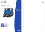
25S, 40S, 55S, 70S, 95S, 110S
880602
Warmlufterzeuger
Space Heater
Générateur d’air chaud
Betriebsanleitung
Operating
Instructions
Notice
d’utilisation
Stand Februar 2006
Inhaltsverzeichnis
Contents
Sommaire
Grundlegende Hinweise ............................ 2
Bestimmungsgemäße Verwendung .......... 3
Grundlegende Sicherheitshinweise ........... 4
Übersicht .................................................... 6
Technische Daten ...................................... 7
Inbetriebnahme .......................................... 8
Wartung .................................................... 10
Montage .................................................... 12
Abgase ..................................................... 13
Basic Instructions ....................................... 2
Designated use .......................................... 3
Securtiy instructions .................................. 4
Overal view ................................................. 6
Technical data ............................................ 7
Setting into operation ................................. 8
Servicing ................................................... 10
Mounting ................................................... 12
Exhaust fumes ......................................... 13
Instruction de base .................................... 2
Designation ................................................ 3
Instruction de base de sécurité ................. 4
Schéma d’ensemble .................................. 6
Carateristiques techniques ........................ 7
Mise en marche ......................................... 8
Entretien ................................................... 10
Montage .................................................... 12
Gaz de combustion .................................. 13
Schaltplan 25S, 40S, 55S, 70S ............... 14
Schaltplan 70S ab 200 Pa ....................... 15
Circuit diagram 25S, 40S, 55S, 70S ....... 14
Circuit diagram 70S up to 200 Pa ........... 15
Schema électrique 25S, 40S, 55S, 70S 14
Schema électrique 70S ........................... 15
Einzelteile 25S bis 70S ............................ 16
Einzelteile 95S und 110S ......................... 18
Component parts 25S to 70S .................. 16
Einzelteile 95S and 110S ......................... 18
Nomenclature 25S jusqu’a 70S ............... 16
Nomenclature 95S et 110S ..................... 18
Einzelteile Brenner 25S bis 55S ............. 20
Einzelteile Brenner 70S ........................... 21
Einzelteile Brenner 95S und 110S .......... 22
Component parts burner 25S to 55S ...... 20
Component parts burner 70S .................. 21
Component parts burner 95S and 110S . 22
Nomenclature brûleur 25S jusqu’a 55S .. 20
Nomenclature brûleur 70S ...................... 21
Nomenclature brûleur 95S et 110S ......... 22
Störungen und Abhilfe ............................. 23
Malfunction and remedy .......................... 24
Les pannes et les moyens d’y remédier . 25
EG-Konformitätserklärung ....................... 26
EC-Conformity .......................................... 26
Déclaration de confometé CE ................. 26
Garantieanforderung ................................ 27
Guarantee request ................................... 28
Demande de garantie .............................. 28
Accessoires .............................................. 31
Accessoires .............................................. 30
Accessoires .............................................. 30
Grundlegende Hinweise
Basic instructions
Instructions de base
Kroll Warmlufterzeuger 25S bis 110S sind
das Ergebnis jahrzehntelanger Erfahrung
und intensiver Entwicklungsarbeit.
wir sind überzeugt, Ihnen ein Spitzenerzeugnis zu übergeben.
Trotzdem müssen die Heizgeräte den jeweiligen Gegebenheiten entsprechend von
einem Fachmann installiert, in Betrieb genommen und durch Messungen überprüft
werden.
Kroll space heaters 25S bis 110S are the
result of thenth of years of experience and
intensif developement work. We are convinced of handing you over a high-quality
product.
Never the less, the heater must be installed
set into operation and tested by measurings correspondending to respective
circustances by a specialist.
Les générateurs d’air chaud 25S - 110S son
le résultat des décennier d’expérience
et de dévelopement intense.
Nous sommes convalincus de transmettre un
produit de haute qualité.
Né ans moins le chauffage doit être installé,
mise en route et tésté en mesurant
conformément aux circonsstance respectives
par un spécialiste.
Betriebsanleitung vor Aufstellung und Inbetriebnahme sorgfältig lesen.
Alle in der Betriebsanleitung beschriebenen
Einzelheiten bezüglich der Aufstellung und
Inbetriebnahme müssen sorgfältig durchgeführt und beachtet werden um einen störungsfreien und energiesparenden Betrieb
zu gewährleisten.
Die Warmlufterzeuger sind nach DIN
4794 Teil 1+3 geprüft und müssen mit
einem Feuerungsautomaten ausgerüstet
sein, der für den Warmlufterzeuger zugelassen ist.
Ausgabe :
880602
Zeichnungs-Nr. 029127-01
Technische Änderungen im Sinne der Produktverbesserung vorbehalten.
Urheberrecht und Hersteller:
Firma Kroll GmbH
2
Read the operation instructions carefully, prior to installing and comissioning the
heater
All details stated, refering tue installation
and setting into operation must be effected
and observed carafully in order to grant an
economic operation free of malfuctions.
Tous détails mentonnés concernant l’installation et la mise en route doivent être et
observés seignieusement pour assurer le
fonctionnement éconique et sans pannes.
The space heaters are proved in
accordance to DIN 4794 part1+3 an must
be equipped with an automatic control
box, which is permitted for the space
heater
Le générateur d’air chaud sont prouvré
selon DIN 4794 part 1+3 et doit être
équipé d’un boîtier d’allumage électrique
qui est admettre dans le générateur
d’chaud
Edition:
8800602
Drawing number:
029127-01
Technical changes in the sense of product
improvement reserved
Privileg of the producer:
Firma Kroll GmbH
Livre attentivement les
instructions de service avant le
montage et la mise en
Edition:
880602
No. du dessin : 029127-01
Toute modification réservée dans le but
d’amélioration du produit
Droit du fabricateur :
Sté Kroll GmbH
Bestimmungsgemäße Verwendung
Designated use / Designation
Überall in folgenden Einsatzbereichen , wo
geheizt werden muß, zur Frostfreihaltung
oder für ein angenehmes Klima sind die
Kroll-Warmlufterzeuger die idealen Partner
Destignated use: Everywhere, where heat is
needed or to keep free of icing or for an
agreable climate Kroll mobil space heaters
are the ideal partners
- Beheizung von Lagerräumen
- für Arbeitsplätze in großen Werkhallen
oder Werkstätten
- Beheizung von Gewächshäusern
- für Verkaufsräume
- heating warehouses and store roomes
- heating of places of work in big shop
floors and workshops
- heating greenhouses
- for assembling and repairing
Domaine d’application: Par tout oú la chaleur
est nécessitée ou pour la maintenance horsgel ou pour la climat agréable, les
générateur d’air chaud Kroll sont les
partenaires idéales :
- le chauffage d’entrepôts
- chauffage des places de travail
dans de grand halls d’usine et des ateliers
- le chauffage de serres
- pour montage et la réparation
Sachwidrige Verwendung
Inappropriate use
Inadéquat traitement
die Warmlufterzeuger sind für
den Hausgebrauch nicht
geeignet und dürfen nur von
Personen bedient werden, die in
der Bedienung unterwiesen
sind.
These space heaters are not
suitable for household use must
be used only by persons who
have been instructed about their
operation
Ces génerateurs d’air chaud ne
sont pas adapté aux emplois
ménagers et ne doivent être
utilisés que par des personnes
introduites en leur fonctionement.
Gewährleistung und Haftung
Zur Erlangung der Garantie ist das Gerät
von einem Fachmann zu installieren und in
Betrieb zu nehmen. Die Einregulierung ist in
einem Meßprotokoll nachzuweisen.
Die Garantieanforderung bitte in allen Punkten richtig auszufüllen, unterschreiben und
an Firma Kroll einsenden. Bitte beachten
Sie, daß bei fehlenden Meßwerten keine
Garantieurkunde ausgefüllt werden kann.
Weitere Voruassetzung für die Garantie ist
eine regelmäßige Wartung, laut der KrollBetriebsanleitung durchzuführen, und mit
den entsprechenden Meßprotokollen nachgewiesen werden muß.
Responsibility
In order to qualify for guarantee, the device
must be installed and commissioned by a
specialist. the settings are to be recorded in
a measurement certificate.
Please fill out all the points of guarantee
form correctly, sign and send it to Kroll.
Please note that in case of missing measuring vales no guarantee certificate will be
issued.
The guarantee will only be granted if a
regular servicing is carried out at least once
a year and in accordance with the Kroll
operating instructions. The results must be
recorded in the applicable measurement
certificates.
Responsabilité
La garantie ne peut être accordée que si
l’appareil a été monté et mise en marche
selon les règles de l’art par un technicien. Le
relevé des réglages doit être démontré dans
un procès ecrit de mesure.
Remplir correctement tous les points de la
demande de garantie, la signer et renvoyer
aux Ets. Kroll. Noter Qu’en cas de valeurs
mesurées manquantes les documents de
garantie ne pourrant être dressés.
L’acceptation de la garantie suppose un
entretien régulier conformément aux
instructions de la maison Kroll, qui doit être
effectué une fois par an et démontré par des
procès cerbaux de mesure y relatifs.
Die allgemeine Garantiezeit für unsere Geräte beträgt 24 Monate nach erfolgter Lieferung, ausschlaggebend ist das Rechnungsdatum.
The usual guarantee period granted on our
device covers 24 months after the delivery the date of the invoice being decisive.
En général, la durée de la garantie pour nos
appareils s’élèveà 24 mois à datr de la
livraison - la date de la facture est déterminante.
Transportschäden
Transportschäden müssen auf dem
Speditionsannahmeschein vermerkt und
vom Fahrer quittiert werden. Technische
Störungen müssen unverzüglich Ihrem
Händler angezeigt werden. Gerät erst nach
Instandsetzung in Betrieb nehmen.
Damage during transport
Transport damages must be noted on the
forwarders receipt and signed by the driver.
Your dealer must be notified of any
technical damage before the appleance is
assembled and set into operation. The
heater is only be started up after competent
repair.
Folgeschäden durch Betriebsausfall der
Warmlufterzeuger sind ausgeschlossen.
Any cases of consequential damage due
to the failure of the space heaters during
operation will be excluded.
Damage during transport
Transport damages must be noted on the
forwarders receipt and signed by the driver.
Your dealer must be notified of any
technical damage before the appleance is
assembled and set into operation. The
heater is only be started up after competent
repair.
Des dégâts de conséquence résultant
d’une interruption des générateurs d’air
chaud sont exclus.
3
Grundlegende Sicherherheitshinweise / Security instructions
Instruction de base de sécurité
Aufstellungsvorschriften
A
B
C
D
E
F
Nach DIN 4794 Teil 5 müssen die Abgase über einen für Öl- oder Gasheizgeräte
genehmigten Schornstein oder Hilfsabzug ins Freie geleitet werden.
Der Schornstein kann gemauert oder
aus Metall sein.
Die Mündung des Schornsteins muß das
Dach um mind. 1 m, den Gebäudefirst
um mind. 0,5 m überragen und in freiem
Windstoß liegen.
Die Mündung des Schornsteins darf
nicht in unmittelbarer Nähe von einem
Fenster oder Balkon liegen.
A
B
The exhaust fumes must be conducted
into the open through a chimney or flue
approved for oil or gas heating
appliances and in acoordance with all
applicable standards.
C
D
E
F
Directives de montage
A
B
C
The chimney can be in masonry or metal
The opening of the chimney must clear
the roof by at least 1 m, and the roof
ridge by at least 0,5 m. It must be exposed to the free wind conditions.
The opening of the chimney must not be
in the vicinity of a window or a balcony.
D
E
F
Selon les normes en vigueur, les gaz
brûlés doivent être évacués par une
cheminée ou par un conduit de fumée
auxilaire agréés pour appareil de
chauffage au fuel ou au gaz. La
cheminée peut être en maçonnerie ou
en métal.
Il faut que la cheminée dépasse le toit
d’au moins 1 m, et le fâitage du bâtiment
d’au moins 0,5 m, et qu’elle soit
dégagée.
La sortie de la cheminée ne doit pas être
placée à proximité immédiate d’une
fenêtre ou d’un balcon.
Abgastemperatur
Bei Inbetriebnahme und Einregulierung
Abgastemperatur auf min. 160°C
einstellen.
Temperature of exhaust fumes
When setting into operation and
adjusting, set temperature of exhaust
fumes for at least 160°C.
Température des gaz brûlés
Lors de la mise en service et du réglage
de l’appareil, régler la temérature de
sortie à 160°C minimum
Installation der Rauchgasrohre
Installation of flue pipes
Am Rohrstutzen muß ein Kapselwinkel
für Regen- und Kondenswasser montiert
werden. Waagrecht verlegte
Abzugsrohre (max. 1/3 der gesamten
Abzugsrohrlänge) benötigen eine
konstante Steigung von mind. 2 cm pro
Meter. Abzugsrohre in Zugrichtung
stecken.
A catch elbow must be connected to the
flue connector for rain-water condesation
Horizontally installed flue pipes (max.1/3
of total flue pipe length) must have a
continuous gradient of 2cm per metre.
Flue pipes must be interconnected in the
direction of the draft.
Installation des tuyaux d’évacation
des gaz
Sur la buse le départ il es recommandeé
de monter un pur l’eau de pluie et l’eau
de condensation.
Les tuyaux posés horizontalement (au
max. 1/3 de la longueur de tuyau totale)
ont besoin d’une déclivité constante d’au
moins 2 cm par mètre.
Emboîtier les tuyaux dans le sens du
tirage.
Installation des Kanalsystems
Maximale Pressung beachten.
Bei Überschreitung fällt die Luftleistung des Ventilators und die
Abgastemperatur, sowie die Ausblastemperatur steigen.
4
Installation regulation
Installation or the pipe system
Pay attention to the maximum
pressure.
If this exceeded, the air volume of the
fan will fall and both the flue gas and
warm air temperature will rise.
Belüftung
Für die Verbrennung muß eine
ausreichende Luftmenge zugeführt
werden (Unterdruck im Aufstellungsraum
vermeiden). Dies ist gegeben, wenn z.B.
der Rauminhalt in m³ mind. der 10fachen
Nennwärmebelastung in kW aller im
Raum betriebenen Geräte entspricht.
Durch Fenster und Türen natürlichen
Luftwechsel sicherstellen. Wenn
Unterdruck und staubhaltige Raumluft
nicht vermeidbar sind, muß der Brenner
verkleidet werden.
Ventilation
Sufficient air for combustion must be
available (avoid low pressure in the
installation room). This is assured when:
e.g. the volume of the room in m³ is a
minimum of 10 times the rated heat load
in kW of all the heating appliances in the
room.
Normal circulation is to be guaranteed
via windows and doors.
If low pressure or dust in the room air
are not avoidable, the burner must be
encased and the air supply taken from
outside the room.
Achtung
Warning
Den Warmlufterzeuger nicht auf
brennbarem Boden aufstellen.
Zum ungehinderten Ansaugen und Ausblasen der Luft ist eine Schutzzone im
Abstand von 1 m freizuhalten.
Außer bei:
- Kanalanschluß
- Pressung
Hinweisschild anbringen:
„Schutzzone 1 Meter Abstand
freihalten“
The space heater is only to be installed
on combustible floor. An area of 1 m
around the heater is to be kept clear to
ensure an unobstructed flow of air to and
from the heater.
Exept from:
- connection conduit
- pressure
Mount a notice:
„Protective zone of 1 m depth to be
kept clear“
- an einer Ansaugseite
- one air inlet side panel
Netzstecker erst ziehen, wenn
das Gerät vollständig abgekühlt
ist.
Remove power supply plug
when the heater has entirely
cooled down.
Installation du système de gainage
Respecter la pression maximale.
S’il y a dépassement de la pression, la
puissance du ventilateur faiblit et la
température des gaz brûlés ainsi que
la température d’air chaud de sortie
montent.
Aération
Pour la combustion, il faut assurer un
apport d’air frais suffisant (eviter une
dépression dans le local). Suffisament
d’air est assuré quand par exemple:
le volume de la pièce en m³ correspond
au minimum à 10fois la charge
calorifique nominale en kW de tous les
appareils qui fonctionnent dans cette
pièce. Assurer une circulation normale
de l’air par les fenêtres et les portes.
Si l’on ne peut pas éviter une dépression
ou de la poussière dans l’air ambiant, il
faut alimenter le brûleur en air extérieur
à l’aide d’un coffrage.
Attention
Ne placer pas le générateur d’air chaud
sur matériaux combustible. Pour libre
circulation de l’air, il faut veiller à laisser
un écartement de 1 m autour de
l’appareil à l’exeption de
- raccordement conduit
- pression
Signaler par un panneau: „Veuillez
respecter un écartement de 1 m autour
de l’appareil. Zone protégée.“
- un paroi d’aspiration
Retirer la prise d’alimentation du
secteur seulement lorsque
l’appareil est complètement
refroidi.
5
Übersicht / Overal view/ Schéma d’ensemble
40S, 55S, 70S, 95S, 110S
Deckel
Cover
Capot
Luftlenkjalousie stirnseitig
Air outlet louvre front side
Lamelles orientables côté frontal
Luftlenkjalousie rechts
Air outlet louvre right
Lamelles orientables
à droit
Luftlenkjalousie links
Air outlet louvre left
Lamelles orientables à gauche
Rückwand
Rear panel
Paroi arrière
Abdeckwand
Cover
Couverture
Seitenwand
Side panel
Paroi latérale
Vorderwand
Front panel
Paroi frontale
Brennerplatte
Burner flange
Bride du brûleur
Öl-/Gasbrenner
Oil-/gasburner
Brûleur fuel/gaz
Umluftwand längsseitig
Side recirculating panel
Paroi latérale air de
circulation
Entstörknopf Brenner
Reset button for burner
Bouton de rearmement
pour brûleur
Wahlschalter
Selector switch
Commutateur
Umluftwand hinten
recirculating rear panel
Paroi arrière air de
circulation
Entstörknopf Sicherheitstemperaturbegrenzer
Reset button overheat thermostat
Bouton de rearmement
limiteur de température
Vorderwand unten
Front panel down
paroi frontale en bas
Störlampe Brenner
Indicator light burner
Lampe de dérangement
brûleur
Schaltgehäuse
Control box
Boîtier de commande
Boden
Bottom plate
Tôle de fond
6
Technische Daten / technical data /
Caracteristiques techniques
Technische Daten
Technical data
Warmlufterzeuger
Space heater
Standard
Ölbefeuert
Standard
Oil-fired
Standard
Brûleur fuel
Brennstoff Öl
Fuel
Brennstoffverbrauch
Fuel consumption
Brennstoff Gas
Gas
Brennstoffverbrauch
Gas consumption
Nominal heating
efficiency
Nennwärmeleistung
Caractéristiques
techniques
Générateur d’air
chaud
Nennwärmebelastung
Rated heat load
Nennluftvolumenstrom
Nominal air delivery
Luftvolumenstrom
Air delivery
Temperaturerhöhung ∆t
Rise in temperature ∆t
Nenndruck
25 S
40 S
2,36
3,4
55 S
70 S
95 S
110 S
8,00
9,30
Combustible
Consommation de
combustible
Gaz
kg/h
Heizöl EL / Fuel oil / Fuel
Consommation gaz
m³/h
2,7
3,8
5,3
6,7
9,1
10,6
Puissance nominal
kW
25,5
37,5
50,5
64
88
100
Puissance calorifique
maximale
Débit d’air nominal
kW
28
40
55
70
95
110
m³/h
1.450
2.710
3.400
4.300
6.000
7.000
4,64
5,9
Erdgas E / Natural gas E / Gaz naturel E
m³/h
1.650
2.900
3.700
5.000
6.750
7650
Kelvin
43
42
45
44
44
44
Nominal pressure
Débit d’air
Augmentation de
température ∆t
Pression nominale
Stromverbrauch
Electrical power
consumption
Consommation
électrique
V/Hz/
A
230~/50/
2,1
400/3N~
3,6
400/3N~
3,6
Elektroanschluss
Electrical connection
Alimentation électrique
kW
0,44
0,8
1,5
1,5
1,5
1,5
Abgasrohr Ø
Flue connector Ø
Tuyau de cheminée Ø
mm
130
130
130
180
180
180
dB(A)
63
65
66
68
69
69
1.150
Geräuschpegel
Sound pressure level
Pression accoustique
Abmessungen
Dimension
Dimension
Frei ausblasend
230~/50/
3,65
230~/50/
6,84
230~/50/
6,9
Länge
Length
Longueur
mm
715
865
975
1085
1.150
Breite
Width
Largeur
mm
455
505
585
665
765
765
Höhe
Height
Hauteur
mm
1275
1500
1645
1835
1.895
1.995
kg
93
124
157
191
245
265
Marzorati
DA10/10
Nicotra
AT15/15
Nicotra
AT15/15
1450
725
765
R20 WLE
oder
ST 133 K
R20-AEWLE
R20-AEWLE
Gewicht ohne Brenner
Weight without burner
Poids sans brûleur
Schutzart
Type of protection
Protection
Gebläse type
Fan type
Ventilateur type
Gebläsedrehzahl
Fan PH
Schornsteinzug
Chimney draft
Nombre de tours
ventilateur
Tirage de cheminée
Ölbrenner-Type
Oilburner type
Brûleur fuel – type
Druck Ölpumpe
Pressure oil pump
Pression de la pompe à
fuel
IP 44
Upm
EBM
D4E180CA02-02
EBM
D4E225CC01-02
Sifan
WAU
08211
1250
1100
1450
mbar
0
R1-V-WLE
R1-V-WLE
R1-V-WLE
bar
11
12
13,5
13
15
20
gph
0,6/60°S
Danfoss
0,85/60°S
Danfoss
1,1/60°S
Danfoss
1,35/60°S
Danfoss
1,75/60°S
Danfoss
1,75/60°S
Danfoss
Düse
Nozzle
Gicleur
Luftklappenstellung
Position air flap
Position clapet d’air
Stellung Düsenstange
Position nozzle bar
Brennerrohrlänge
Length of burner tube
Barre de bec
Longueur tube d’air du
brûleur
Maß „A“
Measure “A”
Dimension “ A “
mm
Maß „B“
Measure “B”
Dimension “ B “
mm
Maß “C”
Measure “C”
Dimension “ C “
mm
11
5
mm
115
7
11
16
19
20
26
35
20
20
40
50
30
Höhere Pressung auf Anfrage / Higher pressure upon on request / Plus pression demande le fabricant
7
Inbetriebnahme / setting into operation /
Mise en marche
Die Steuerung des Warmlufterzeugers und
des Brenners erfolgt über den Wahlschalter
über den Raumthermostat oder die Tag- und
Nachtautomatik
The space heater and burner are controlled
by the selector switch and by means of a
room thermostat or via control for week
program
Stromanschluß
La commande du générateur d’air chaud et
du brûleur s’effectue par le commutateur et
le thermostat d’ambiance ou par le control
nuit-jour
Power connection
Raccordement électrique
Am Stromnetz 230V/50Hz anschließen.
Auf Baustellen entsprechend VDE 0100,
Teil 704 an besonderen Speisepunkten mit
Fehlerschutzstromeinrichtung anschließen
Connect to 230V/50Hz
On building sites the connection to the
mains electrical isolator must be in
accordance to your country’s regulations.
Raccorder au reseau 230V/50Hz.
Selon normes en vigueur.
Heizen mit Raumthermostat
Heating with room thermostat
The space heater heats up.
When internal temperature of the appliance
reaches +40°C (factory setting), the fan is
set into operation.The burner switches off
when the set room temperature is reached.
The burner is automatically switched on
again when the room temperature falls
below this value.
Chauffage avec thermostat d’ambiance
1 Regler le commutateur sur position
Chauffage
2 Indiquer la température ambiante
désirée.
Le générateur d’air chaud est préchauffé.
Lorsque l’intérieur de l’appareil a atteint
+40°C, le ventilateur se met en route.
Lorsque la température ambiante est
obtenue le brûleur s’arrête.
Quand la température ambiante descend
en-dessous de la température désirée, le
brûleur se remet en route automatiquement.
Heating with day/night mechanism
Chauffage avec jour/ mécanisme de nuit
1 Wahlschalter auf
Heizen stellen
1
Set selector switch to
Gewünschte Raumtemperatur am
Raumthermostat einstellen
Der Warmlufterzeuger wird aufgeheizt. Bei
+ 40°C Gerätetemperatur (Werkseinstellung) wird das Gebläse in Betrieb
gesetzt. Nach Erreichen der eingestellten
Raumtemperatur schaltet der Brenner ab.
Nach Unterschreitung der eingestellten
Raumtemperatur schaltet der Brenner
automatisch wieder ein.
2
Set the desired room temperature
2
Heizen mit Tag- und Nachtautomatik
3
4
Tag- und Nachtautomatik installieren
und gemäß Betriebsanleitung programmieren - danach Vorgehensweise wie
„Heizen mit Raumthermostat“
Heizen ohne Raumthermostat
5
Wahlschalter auf
Heizen stellen
3
4
Heating
Instal control for week program
according technical manual when
follow as if „heating with room
thermostat“
Heating without room thermostat
5
Set selector switch to
Heating
Der Warmlufterzeuger wird aufgeheizt. Bei
+ 40°C (Werkseinstellung) Geräteinnentemperatur wird das Gebläse in Betrieb
gesetzt. Nach Überschreitung bzw. Unterschreitung der eingestellten Temperatur
(Werkseinstellung + 80°C) schaltet der
Temperaturwächter den Brenner ab bzw.
wieder ein.
The space heater heats up. When internal
temperature of the appliance reaches +40°C
(factory setting), the fan is set into operation.
If the set temperature (factory setting +80°C)
is exceeded, or if the temperature falls below this level, the temperature controller
switches the burner off, or on again, as the
case may be.
Abschalten mit/ohne Raumthermostat
Turning off with/without room thermostat
6
Wahlschalter auf „0“ stellen
Ein mehrmaliges Anlaufen des
Gebläses dient zur Abführung der im
Warmlufterzeugers verbliebenen Restund Stauwärme.
Das Gebläse muß Brennkammer und
Wärmetauscher abkühlen Überhitzungsgefahr !
Erst nach Abkühlung des Warmlufterzeugers Strom- und Hauptschalter
abschalten.
Zuwiderhandlung schließt Werksgarantie aus.
Lüften
7 Wahlschalter auf
Lüften stellen
Das Gebläse läuft ohne Brenner im
Dauerbetrieb für die Raumbelüftung.
(Vorhandenen Raumthermostat auf
0°C stellen)
8
6
Set selector switch to „0“
The fan will repeatedly start up in
order to remove residual heat from the
space heater.
3
4
Installéz le control nuit-jour selon
manual technique, puis procédez
comme „chauffer avec thermostat
d’ambiance“
Chauffage sans thermostat d’ambiance
Regler le commutateur sur position
5
Chauffage
Le générateur d’air chaud est préchauffé.
Lorsque l’intérieur de l’appareil a atteint
+40°C (réglage d’usine), le ventilateur se
met en route. Si la température excède la
valeur mini ou maxi indiquée (réglage en
usine à 80°C), le thermique limite remet le
brûleur en route ou l’arrête.
Arret avec/sans thermostat d’ambiance
6
Régler le commutateur sur position „0“
Un démarrage répéte du ventilateur a
pour but d’éliminer la chaleur retenue à
l’interieur de l’appareil.
The fan must cool the combustion
chamber and heat exchanger danger of over-heating !
Le ventilateur doit refroidir la chambre
de combustion et l’échangeur de
chaleur - danger de surchauffe !
Do not switch off electrical supply and
master switch until the space heater
has cooled down.
Non-compliance invalidates the
factory guarantee.
Il faut attendre le refroidissment
complet du générateur d’air chaud
avant de couper l’interrupteur principal
et l’alimentation électrique.
Un non-respect de ces indications
exclut l’acception de garantie
d’usine.
Ventilation
7 Set selector switch to
Ventilation
The fan runs continuously with the
burner for the room ventilation
(In cas of a room thermostat set to
0°C)
Ventilation
7 Régler le commutateur sur position
Ventilation.
Le ventilateur tourne „sans“ brûleur, en
fonctionnement en continu pour
l’aération du local. (S’il y a thermostat
d’ambiance, le régler sur 0°C
Heizen mit Raumthermostat
Heating with room thermostat
Chauffage avec thermostat
d’ambiance
Heizen mit
Tag- und Nachtautomatik
Heating with day/night
mechanism
Chauffage avec
jour/mécanisme de nuit
Heizen ohne Raumthermostat
Heating without room
thermostat
Chauffage sans thermostat
d’ambiance
Abschalten
Switching off
Arrêt
Lüften
Ventilation
Ventilation
9
Wartung / Servicing / Entretien
Wartung
Wartung
Der Wärmetauscher und die Brennkammer
sollten nach DIN 4794 mind. einmal pro
Jahr gründlich gereinigt und durch einen
Fachkundigen geprüft werden.
The heat exchanger and the combustion
chamber should be thoroughly cleaned and
checked by a specialist at least once a year.
Die Firma Kroll empfiehlt, einen Wartungsvertrag abzuschließen.
Kroll recommends taking out a service
contract.
Bei allen Arbeiten am Warmlufterzeuger Wahlschalter auf „0“
stellen. Nach Abkühlung des
Warmlufterzeugers unbedingt
Strom-Hauptschalter abschalten.
1
Reinigung
Brennkammer
2
10
Cleaning of
combustion chamber
4 Besfetigungsschrauben am Brennerflansch lösen und den Brenner
abnehmen
Loosen 4 clamping bolts on burner
bracket. Remove burner.
Lors de tous travaux sur le
générateur d’air chaud, il faut
positionner le commutateur sur „0“.
Après refroidissement du générateur
d’air chaud, il faut absolutement
débrancher l’interrupteur général.
1
Débrancher le courant électrique
(voir ci-dessus).
Désserer les 4 vis de fixation à la bride
du brûleur et enlever le brûleur
Par l’ouverte, nettoyer la chambre de
combustion à l’aide d’une brosse et
d’un aspirateur
Fixer le brûleur avec les 4 vis de
serrage à la bride du brûleur
Clean combustion dchamber with
brush and vacuum cleaner through the
opening
Fixing the burner with 4 clamping
screws on the burner bracket.
2 Cleaning of heat exchanger -
Nettoyage de la
chambre de combustion
2
Strom abschalten (siehe oben)
Turn off electrical supply (see above)
Nach Entfernen der Vorderwand
Reingungsdeckel abschauben,
Dichtungsband entfernen und mittels
Bürste und Staubsauger reinigen.
After have removing the corresponding
front panel, loosen the cleaning cover,
remove the seal and clean by means of
brush and aspirator.
Nettoyer d’échangeur de chaleur côte d’aspiration
Débrancher le courant électrique
(voir ci-dessus)
Après avoir enlevé le paroi frontale
corréspondants, dévisser le couvercle
de nettoyage, enlever le joint et
nettoyer par brosse et aspirateur.
Danach neues Dichtungsband
anbringen und in umgekehrter
Reihenfolge wieder zusammenbauen.
Put on new seals and mount in
reversed order.
Puis mettre un nouveau joint et
remonter à l’ordre inversé.
Reinigung
Wärmetauscher - Ansaugseite
3
1
Turn off electrical supply (see above)
Brenner mit den 4 Befestigungsschrauben wieder am Brennerflansch
anschrauben
Conformément à la norme DIN 4794,
l’échangeur de chaleur et chambre de
combustion doivent être nettoyés à fond et
vérifiés au moins une fois par un
spécialiste.
La société Kroll conseille de souscrire à un
contract d’entretien.
Set selector switch to „0“ before
starting maintenance work on the
space heater.
After the heater has cooled down,
the main power switch must be
turned off.
Strom abschalten (siehe oben)
Brennkammer mit Bürste und Staubsauger durch die Öffnung reinigen
Wartung
Reinigung
Wärmetauscher - Ausblasseite
suction side
3 Cleaning of heat exchanger air outlet side
3
Nettoyer d’échangeur de chaleur côte soufflage
Strom abschalten (siehe oben)
Turn off electrical supply (see above)
Nach Entfernen der entsprechenden
Gehäusewände Reinigungsdeckel
abschrauben, Dichtungsband
entfernen und mittels Bürste und
Staubsauger reinigen.
After having removed the
corresponding side panesl, loosen the
cleaning cover, remove the seal and
clean by means of brush and aspirator.
Débrancher le courant électrique
(voir ci-dessus)
Après avoir enlevé les parois latérales
corréspondants, dévisser le couvercle
de nettoyage, enlever le joint et
nettoyer par brosse et aspirateur.
Danach neues Dichtungsband
anbringen und in umgekehrter
Reihenfolge wieder zusammenbauen.
Then put on new seals and mount in
reversed order
Puis mettre un nouveau joint et
remonter à l’ordre inversé.
3
3
3
2
2
3
1
3
3
Brenner - Kundendienst
Der Brenner sollte mindestens einmal
im Jahr überprüft und einreguliert
werden, dabei muß der Ölfiltereinsatz
überprüft werden.
Die Arbeiten dürfen nur vom Kundendienst oder einem autorisierten
Fachbetrieb vorgenommen werden.
Burner after sales service
The burner should be checked and
adjusted once anually. On this
occasion, the oil filter insert and the
burner jet have to be replaced.
This work must only be made by after
sales service or an authorized
specialist firm.
Service après-vente brûleur
Le brûleur devrait être vérifié et réglé
au moins une fois par an. En cette
occurance, le cartouche filtrante et la
buse du brûleur doivent être remplacées.
Ces travaux ne doivent être effectués
que par le service après vente ou bien
un spécialiste agréé.
Reinigung Luftfilter
Bei Warmlufterzeugern mit Luftfilter
sollten diese entsprechend der
Verunreinigung gereinigt oder erneuert
werden.
Cleaning the air filter
Air filters should be cleaned or
replaced, depending on their condition.
Nettoyage des filtres à air
Lorsque les générateurs d’air chaud
sont équipés de filtres à air, ceux-ci
devront être nettoyés ou remplacés si
nécessaire.
11
Montage / Mounting / Montage
Den Warmlufterzeuger
a) nur an feuersicheren Wänden und nach
DIN 4794 Teil 5 montieren
b) waagrecht aufstellen
c) bei der Aufstellung des Warmlufterzeugers
sind folgende Richtlinien und Normen
einzuhalten:
DVGW-TRGI 1986
DIN 4756 und TRF 1988
DVGW Arbeitsblatt G 600
Bei der Aufstellung unter Erdgleiche sind
besondere Anforderungen der
TRF 1988 einzuhalten
Elektroanschluß
Der Elektroanschluß muß nach DIN 4794
Teil 5 Absatz 7 erfolgen und darf nur von
einem zugelassenen Fachbetrieb vorgenommen werden.
Bei Drehstrommotor auf richtige Laufrichtung achten.
Motorschutz richtig einstellen.
Raumthermostat
Montage nicht in kaltem oder warmem
Luftstrom.
Gasanschluß
Der Anschluß muß entsprechend DVGWArbeitsblatt G 600 (DVGW-TRGI) erfolgen.
Anschluß und Inbetriebnahme dürfen
nur von einem zugelassenen GasInstallateur vorgenommen werden.
Gaszufuhr und Anschluß auf absolute
Dichtheit prüfen.
Brenner auf örtliche Gasverhältnisse
einstellen. Vor Inbetriebnahme Elektroanschlüsse vornehmen.
Ölanschluß
Der Anschluß erfolgt durch den Brennerkundendienst und muß nach DIN 4794
Teil 5, Absatz 6 ausgeführt werden.
Ol- oder Gasbrenner
Die Einstellung und Inbetriebnahme darf nur
vom Kundendienst des jeweiligen Brennerfabrikates oder eines autorisierten Fachbetriebes vorgenommen werden.
Die vom Brennerhersteller angegebenen
Werte sind unbedingt einzuhalten.
Brennerkundendienst
Die Firma Kroll empfiehlt, einen Wartungsdienst abzuschließen.
12
Mount the space heaters
a) only on fire proof walls and according to
the relevant standards (equivalent to
DIN 4794 part 5)
b) Mount levelly
c) The installation of the space heater must
comply with the building regulations and
all other applicable standards an legislation and standards:
DVGW-TRGI 1986
DIN 4756 und TRF 1988
DVGW Standard G 600
Additional technical regulations
TRF 1988
are to be observed when installing space
heaters in room ground level.
Power connection
The electrical connection must be carried
out to the applicable standard (equivalent to
DIN 4794 part 5 paragraph 7) and only by
an approved specialist firm. Pay attention to
correct running direction with the threephase A.C-motors. Set motor protector to
correct value.
Roomthermostat
Do not mount in cold or warm air stream.
Gas connection
The connection must be carried out in
accordance with the applicable technical
regulations.
Connection and setting into operation
must be carried out by a qualified gasfitter.
Check gas supply and connection for leaks.
Adjust burner to local conditions.
Check electrical connection before setting
into use.
Oil connection
The connection will made by the burner
service.
Oil- or gas burner
The adjustment and setting into operation
may only be carried out by the after-sales
service of the respective burner
manufacturer or an authorized specialist
firm.
The values given by the burner
manufacturer must be complied with.
Burner service
Kroll recommends taking out a service
contract.
Suspendre le générateur d’air chaud
a) Installation uniquement contre des parois
incombustibles et selon norme DIN 4794
partie 5
b) de niveau
c) Lors de l’installation du générateur d’air
chaud, il faut observer les prescritions et
les normes en vigueur:
DVGW
Dans le cas d’une mise en place en
dessous du niveau du sol, il faudra se
mettre en conformité avec la norme
TRF 1988
Raccordement électrique
Le raccordement électrique doit respecter la
norme DIN 4794 partie 5, paragraphe 7 et
doit être obligatoirement effectue, par un
technicien agrée, dans les regles de l’art.
Thermostat d’ambiance
Montage à une endroit approprie hors de
portée d’un courant d’air froit ou chaud.
Raccordement gaz
Le raccordement doit se faire selon les
normes techniques en vigueur.
Raccordement est mise en service ne
doivent être effectuès que par des
installateurs agrées.
Vérifier l’étanchéité absolue de l’arrivée de
gaz ainsi que du raccordement.
Régler le brûleur selon les normes
régionales.
Effectuer les raccordements électriques
avant la mise en service.
Raccordement au fuel
Le raccordement s’éffectue par le service
après vent du brûleur.
Brûleur au fuel ou au gaz
Le réglage et la mise en service du brûleur
doivent être exécutés par le service après
vente du fabricant des brûleurs ou par un
spécialiste agréé.
Les valeurs indiquées par le constructeur
des brûleurs sont à respecter
impérativement.
Service après vente brûleurs
Le societé Kroll conseille de souscrire à un
contract d’entretien.
Abgase / Exhaust fumes/ Gaz de combustion
Die Mündung des Abgasrohres muß das Dach
um mind. 1 m und den Gebäudefirst um
mind. 0,5 m überragen und im freien Windstoß liegen.
The opening of the flue pipe must clear the
roof at least 1 m uand the roof ridge by
at least0,5 m . It must also be exposed to the
free wind conditions.
Il faut que la cheminée dépasse le toit d’au
moins 1 m et le fâtage du bâtiment d’au
moins 0,5 m et qu’elle soit placée à l’abri des
coups de vent.
Die Mündung des Abgasrohres darf nicht in
unmittelbarer Nähe von einem Fenster oder
Balkon liegen.
The opening of the flue pipe must not be in the
vincinity of a window or a balcony.
La sortie de la cheminée ne doit pas être
placée à proximité immédiate d’une fenêtre
ou d’un balcon.
Installation
Installation
Installation
Am Rohrstutzen muß ein Kapselwinkel für
Regen- und Kondenswasser montiert werden.
Waagrecht verlegte Abzugsrohre (max. 1/3 der
gesamten Abzugsrohrlänge) benötigen eine
konstante Steigung von mind. 20 mm pro
Meter. Abzugsrohre in Zugrichtung stecken.
A catch elbow must be connected to the flue
connector for rain-water and condensation.
Horizontally installed flue pipes (maximum only
on third of the total flue pipe length) must have
a continuos gradient of 20 mm per meter.
Flue pipes must be interconnected in the
direction of the draft.
Sur la buse de départ il est recommandé té de
monter un pour de pluie et l’eau de
condenstion.
Le tuyaux posés horizontalement (au max 1/3
de la longueur de tuyau totale) ont besoin
d’une déclivité constante d’au moins 20 mm
par mètre .
Emboîtier les tuyaux dans le sens du tirage.
Inbetriebnahme zum Probelauf
Setting into operation for test run
Mise en marche en course d’essai
Wahlschalter betätigen - Heizen ohne Raumthermostat
Set selector switch to - Heating without room
thermostat
Régler le commutateur sur position Chauffage sans thermostat d’ambiance
Abschalten
Wahlschalter auf „0“ stellen
Turning off
Set selctor switch to „0“
Arrêt
Régler le commutateur sur position „0“
Überprüfen der Meßwerte nach den
technischen Daten und Eintragen in die
Garantie-Anforderung
Examining of the measuring values
according to technical data and registering
in the demand for garanty
Examination des valeurs selon donnés
technique et registration dans la demande
de guarantie
13
Schaltplan / Circuit diagram / Schéma électrique
25S, 40S, 55S, 70S
B1
Raumthermostat
B1
Room thermostat
S1
Thermostat d’ambiance
B2
Lüfterthermostat
B2
Thermostat fan
B2
Thermostat ventilateur
B3
Sicherheitstemperaturbegrenzer
B3
Overheat thermostat
B3
Limiteur de température
B4
Brennerthermostat
B4
Burner thermostat
B4
Thermostat du brûleur
C1
Motorenkondensator
C1
Capacitor for motor
C1
Condensateur pour moteur
H1
Störlampe
H1
Indicator light
H1
Lampe de dérangement
M1
Lüftermotor
M1
Fan motor
M1
Moteur ventilateur
S1
Wahlschalter
S1
Selector switch
S1
Commutateur
TK1
Thermojunction
TK1
TK1
Contact
X1
Feuerungsautomatik
X1
Burner control
X1
Commande automatique
du brûleur
X2
Brennerstecker
X2
Burner plug
X2
Prise du brûleur
X3
Connecting strip
Control box
X3
Barre à bornes boîtier
De commande
X3
14
Thermokontakt
Klemmleiste Schaltgehäuse
Schaltplan / Circuit diagram / Schéma électrique
für 400 V Motoren / for 400 V Motors / pour 400V Moteurs
Bei Anschluß eines Raumthermostates
Brücke zwischen
Klemme 5 und 6 entfernen
Remove bridge connector 5 -6
when room thermostat is connected
Pour raccordement d’un thermostat
d’ambiance enlever le shunt entre
5 et 6
B1
Raumthermostat
(Option)
B1
Room thermostat
(Option)
S1
Thermostat d’ambiance
(Optional)
B2
Lüfterthermostat
B2
Thermostat fan
B2
Thermostat ventilateur
B3
Sicherheitstemperaturbegrenzer
B3
Overheat thermostat
B3
Limiteur de température
B4
Brennerthermostat
B4
Burner thermostat
B4
Thermostat du brûleur
F1
Steuersicherung
F1
Fuse
F1
Fusible
F2
Motorschutzrelais
F2
Motor-protection relay
F2
Relais tôle de capotage
H1
Störlampe
H1
Indicator light
H1
Lampe de dérangement
K1
Motorschütz
K1
Contactor
K1
Contacteur
M1
Lüftermotor
M1
Motor ventilation
M1
Moteur entilateur
S1
Wahlschalter
M1
Selector switch
M1
Commutateur
TK1
X1
Thermojunction fan
motor (if available)
Burner control
TK1
X1
Thermokontakt Lüftermotor
(falls vorhanden)
Feuerungsautomatik
Contact thermique moteur
ventilateur (si existant)
Commande automatique du
brûleur
X2
Brennerstecker
X2
Burner plug
X2
Prise du brûleur
X3
Klemmleiste Schaltgehäuse
X3
Connecting strip
Control box
X3
Barre à bornes boîtier
de commande
TK1
X1
15
Einzelteile 25 S bis 70 S
Component part 25S to 70S / Nomenclature 25S jusqu’a 70S
1
2
5
3
6
11
4
12
38
39
14
7
8
9
13
10
37
36
15
35
16
34
33
27
32
29
28
31
25
26
17
21
20
19
24
18
23
30
22
Position 32 - Schaltgehäuse
Position 32 - Control box
Position 32 - Boîtier de commande
25 S bis 70 S
32
Schaltgehäuse
a
Verschlußschraube Screw plug
b
c
Signalleuchte rot
Sicherheitstemperaturbegrenzer
Signal lamp red
Lampe témoin rouge
Overheat thermostat Limiteur de
température
006501
026704
d
Nockenschalter
Snap sw itch
Combinateur à cames
028307
e
Kabelverschraubung Cable screw
Raccord de câble
023158
f
g
Gegenmutter
Temperaturregler
023208
026705
h
Temperaturw ächter
i
k
Schaltgehäuse
Zugfederklemme
grau
Zugfederklemme blau
Contre-écrou
Régulateur de
température
Contrôleur de
température
Boîtier de commande
Barre à bornes gris
027185
025452
c
Barre à bornes blue
025451
b
k
l
Barre à bornes
verte/jaune
Raccord de câble 3x
025453
a
m
Locking corner
Temperature
regulator
Overheat thermostat
Boitier de commande
027946
Vis de fermeture
023204
n
o
Gegenmutter 3x
Locking corner
Contre-écrou
023209
p
Brennerkabel
Burner cable
Câble du brûleur
029251
r
Kondensator
25S = 10µF
Capacitor
25S = 10µF
Condensateur
25S = 10µF
005715
40S = 25µF
40S = 25µF
40S = 25µF
005590
m
e
f
g
h
i
d
026706
Control box
Connecting strip
grey
Connecting strip
blue
Zugfederklemme
Connecting strip
grün/gelb
green/yellow
Kabelverschraubung Cable screw ing 3x
l
16
Control box
c
022993
r
p
o
n
Bestell-Nr.
Requisition number
Numéro de commande
Ein z e lt e ile
C o m p o n e n t p ar ts
No m e n c la t u r e
25 S
40 S
1 L u f tle n kja lo u s ie
A ir o u lle t lo u v r e
2 S e ite n w a n d
S id e p a n e l
L a me lle s o rie n ta b le s
0 2 7 86 3
Pa ro i la té r a le
0 2 8 06 1
3 S tr a h le n s c h u tz
S e ite n w a n d
Pr o te c tiv e s c r e e n
s id e p a n e l
Ma n te a u in té r ie u r
p a ro i la té r a le
4 W ir b u la to r
Tu b u la to r
5 De c ke l
Cov e r
6 Re in ig u n g s d e c ke l
C le a n in g c o v e r
Dic h tu n g s b a n d
7 S p a n n r in g
55 S
70 S
0 0 5 41 5
0 54 9 9
0 0 5 49 8
0 2 8 07 8
0 2 8 09 5
0 2 8 04 2
0 2 8 06 5
0 2 8 08 2
0 2 8 09 9
0 2 8 04 6
Tu rb u la te u r
0 2 9 22 8
0 2 9 22 8
0 2 9 22 8
0 2 9 22 8
Co u v e r c le
0 2 8 06 3
0 2 8 08 0
0 2 8 09 7
0 2 8 04 4
Co u v e r c le d e n e tto y a g e
0 2 7 85 3
0 2 7 85 3
0 2 7 85 3
0 2 7 85 3
S ea l
Jo in t
0 0 5 25 6
0 0 5 25 6
0 0 5 25 6
0 0 5 25 6
C la mp in g rin g
Te n d e u r
0 0 1 30 5
0 0 1 30 5
0 0 1 30 5
0 0 1 31 4
0 0 1 77 3
8 Z e n tr ie r r in g
C e n trin g
Ce n tr a g e
0 2 7 21 3
0 2 7 21 3
0 2 7 21 3
9 Du rc h z u g s d ic h tu n g
S ea l
Jo in t
0 1 2 83 4
0 1 2 83 4
0 1 2 83 4
0 1 1 56 3
C o mb u s tio n c h a mb e r
Ch a mb r e d e c o mb u s tio n
0 2 7 81 8
0 2 7 89 0
0 2 7 90 4
0 2 7 84 1
1 0 B r e n n ka mme r
1 1 W ä r me ta u s c h e r
Hea t e x c h a ng e r
Ec h a n g e u r d e c h a le u r
0 2 7 82 3
0 2 7 89 5
0 2 7 90 9
0 2 7 84 7
1 2 Re in ig u n g s d e c ke l
C le a n in g c o v e r
Co u v e r c le d e n e tto y a g e
0 2 7 85 3
0 2 7 85 3
0 2 7 85 3
0 2 7 85 3
S ea l
Jo in t
0 0 5 25 6
0 0 5 25 6
0 0 5 25 6
0 0 5 25 6
1 3 S tr a h le n s c h u tz
Dic h tu n g s b a n d
Pr o te c tiv e s c r e e n
Ma n te a u in té r ie u r
0 2 8 06 6
0 2 8 08 3
0 2 8 10 0
0 2 8 04 7
1 4 Rü c kw a n d
Rea r p a n el
Pa ro i a r r iè re
0 2 8 06 2
0 2 8 07 9
0 2 8 09 6
0 2 8 04 3
1 5 Umlu f tw a n d
R e c ir c u la tin g p a n e l
Pa ro i d e r e p r is e d 'a ir
0 2 8 05 6
0 2 8 07 2
0 2 8 09 1
0 2 8 03 8
1 6 S e ite n w a n d
S id e p a n e l
Pa ro i la té r a le
0 2 8 06 1
0 2 8 07 8
0 2 8 09 5
0 2 8 04 2
1 7 L u f tle n kja lo u s ie
A ir o u lle t lo u v r e
L a me lle s o rie ta b le s
0 2 7 86 3
0 0 5 41 5
0 54 9 9
0 0 5 49 8
1 8 Umlu f tw a n d
R e c ir c u la tin g p a n e l
Pa ro i d e r e p r is e d 'a ir
0 2 8 05 3
0 2 8 07 1
0 2 8 08 8
0 2 8 03 6
1 9 S tr a h le n s c h u tz
S e ite n w a n d
Pr o te c tiv e s c r e e n
s id e p a n e l
Ma n te a u in té r ie u r
p a ro i la té r a le
0 2 8 06 5
0 2 8 08 2
0 2 8 09 9
0 2 8 04 6
2 0 L e itb le c h
A ir g u id e
Tô le d e c h ic a n e d 'a ir
0 2 8 71 8
0 2 8 67 2
0 2 8 71 9
0 2 8 63 2
2 1 S tü tz p r o f il
S u p p o rt
Su p p ort
0 2 8 04 9
0 2 8 06 7
0 2 8 08 4
0 2 8 03 1
2 2 Bo de n
B o tto m p la te
Tô le d e f o n d
0 2 8 05 1
0 2 8 06 9
0 2 8 08 6
0 2 8 03 3
2 3 Ra d ia lg e b lä s e
Fa n r a d ia l
V e n tila te u r r a d ia l
0 0 5 39 4
0 0 5 78 9
0 0 5 94 6
0 0 5 77 2
2 4 Z w is c h e n b o d e n
In te r me d ia te b o tto m
Fo n d in te r mé d ia ir e
0 2 8 05 8
0 2 8 07 5
0 2 8 09 2
0 2 8 03 9
2 5 Is o lie r u n g
In s u la tin g
Is o la te u r
0 2 7 00 4
0 2 7 00 4
0 2 7 00 4
0 2 7 00 4
2 6 B r e n n ka mme r
G e g e n f la n s c h
C o u n te r f la n g e
c o mb u s tio n c h a mb e r
Co n tr e - b r id e c h a mb r e d e
c o mb u s tio n
0 2 6 38 6
0 2 6 38 6
0 2 6 38 6
0 2 6 38 6
2 7 B r e n n e r p la tte
B u r n e r d is k
Pla q u e d e b r û le u r
0 2 8 59 3
0 2 8 59 3
0 2 8 59 3
0 2 8 59 3
2 8 Bren n e r
B urn e r
B r û le u r
0 2 7 48 5
0 2 7 48 6
0 2 7 48 7
0 0 5 78 5
2 9 S tr a h le n s c h u tz
Pr o te c tiv e s c r e e n
Ma n te a u in té r ie u r
0 2 8 06 4
0 2 8 08 1
0 2 8 09 8
0 2 8 04 5
3 0 V o r d e r w a n d u n te n
3 1 Ha lte b le c h
S te u e rg e r ä t
Fr o n t p a n e l b e lo w
Mo u n tin g s u p p o r t
c o n tr o l b o x
Pa ro i f r o n ta le e n d e s s o u s
Su p p ort
b o îtie r d e c o mma n d e
0 2 8 05 2
0 2 8 54 1
0 2 8 07 0
0 2 8 54 1
0 2 8 08 7
0 2 8 54 1
0 2 8 03 4
0 2 8 54 1
3 2 S c h a ltg e h ä u s e
C o n tro l b o x
B o îtie r d e c o mma n d e
0 2 7 94 6
0 2 7 94 6
0 2 7 94 6
0 2 7 94 6
3 3 A b d e c kw a n d
Cov e r
Ca p o t
0 2 8 06 0
0 2 8 07 7
0 2 8 09 4
0 2 8 04 1
3 4 L u f tle n kja lo u s ie
A ir o u lle t lo u v r e
L a me lle s o rie ta b le s
0 2 7 86 3
0 2 7 68 3
0 0 5 41 5
0 0 5 49 9
3 5 V o rd erw a nd
Fr o n t p a n e l
Pa ro i f r o n ta le
0 2 8 05 9
0 2 8 07 6
0 2 8 09 3
0 2 8 04 0
3 6 S tü tz p r o f il
S u p p o rt
Su p p ort
0 2 8 04 9
0 2 8 06 7
0 2 8 08 4
0 2 8 03 1
3 7 L e itb le c h
A ir g u id e
Tô le d e c h ic a n d e d 'a ir
0 2 8 71 8
0 2 8 67 2
0 2 8 71 9
0 2 8 63 2
3 8 Re in ig u n g s d e c ke l
C le a n in g c o v e r
Co u v e r c le d e n e tto y a g e
0 2 7 23 0
0 2 7 23 0
0 2 7 26 3
0 2 6 36 6
S ea l
Jo in t
0 0 5 25 6
0 0 5 25 6
0 0 5 25 6
0 0 5 25 6
R e c ir c u la tin g p a n e l
Pa ro i d e r e p r is e d 'a ir
0 2 8 05 3
0 2 8 07 1
0 2 8 08 8
0 2 8 03 6
Dic h tu n g s b a n d
3 9 Umlu f tw a n d
17
Brenner ST 133 K / Burner ST 133 K / Brûleur ST 133 K
1
2
3
4
5
6 7
Brennereinstellung
Burner adjustment
Reglage de brûleur
8
9
10
11
12
112mm
13
Kesselanschluss
Boiler connection
Raccordement de chaudière
89,7
18
17
16 15
14
10,3
19
130 - 150
Brenne r Pos. 28
70S
1
Entstörtaste
Reset Button
Bouton de rearmement
2
Steuergerät Oberteil
Control box top
Boîtier de commande
partie supérieure
028697
3
Zündtransformator
Transformer
Transformateur d'allumage
028167
4
Zündkabel
Ignition cable
Câble d'allumage
028699
5
Düsenstock
Nozzle connection
Ligne-gicleur
028700
Ölleitung
Oil line
Tube d'huile
028701
Ölvorwärmung
Oil preheating
Préchauffage du fuel
Elektrodenhalter
Electrode holder
Porte-électrode
028657
auf Anfrage
on request
sur demande
6
Düse
Nozzle
Gicleur
7
Stauscheibe
Flame ring
Accroche flamme
028181
8
Brennerrohr
Burner tube
Tube d'air du brûleur
028704
9
Zündelektrode
Ignition electrode
Electrode d'allumage
028189
10 Öldruckrohr
Oil pressure pipe
Tuyau pression d'huile
028706
11 Luftklappe
Air damper
Clapet d'air
028195
12 Magnetventil
Solenoid valve
Electrovanne
028198
13 Pumpe
Pump
Pompe
028199
14 Antriebskupplung
Coupling
Accouplememt
028203
15 Gebläserad
Fan buffle
Ailette
028207
16 Anzeige Luftklappe
Indicator air damper
Indicateur clapet d'air
028204
17 Einstellung Luftklappe
Adjustment air damper
Réglage clapet d'air
028211
18 Fotowiderstand
Photocell
Cellule photoélectrique
028212
19 Motor
Motor
Moteur
028216
Mindesteinstecktiefe 110 mm
Min. insert depth
110 mm
Profondeur min.
du tube du brûleur 110 mm
21
Malfunction and remedy
Warning !
All work on the electrical installation must be carried out by a qualified electricien.
Pull power supply plug only when the heater has entirely cooled down.
See also operating instructions for oil-/gasburner.
Malfunction
The space heater ist connected up, but :
The heater does not start, when
the
selector switch is set to heating
The space heater is connected up and
switched on:
The oil burner starts and
immediately indicates a
malfunction
Possible Cause
Remedy
a)
b)
c)
No electrical supply
Defective selector switch
Oil-/gasburner indicates a
malfunction
a)
b)
c)
Check main switch and fuses
Replace selector switch
Reset oil-/gasburner if burner cuts
again, press reset button after 4 to
5 min.
See operating instruction for burner
Press reset button of overheat
thermostat
Check room thermostat setting
d)
Overheat thermostat is locked
d)
e)
Room thermostat falsely set
e)
a)
b)
No oil in the tank
Air in fuel circuit
a)
b)
Refill oil tank
Check screwed connections of fuel
circuit for leaks
c)
d)
e)
c)
d)
e)
Change filter element
Open stopcock
See operating instructions oil burner
a)
Check manometer admission
pressure
Check if main shut-off valve are in
the „open-position“
the gas burner starts and
immediately indicates a
malfunction
a)
Oil filter clogged
Stopcock closed
Oil burner indicates a malfunction
again
No gas pressure
Overheat thermostat switches off
a)
Defective temperature controller
a)
Replace warm air thermostat
Temperature controller continually
switches off
a)
Temperature controller wrongly set
a)
b)
Fan does not start
b)
Check temperature controller
setting
Check fan motor or capacitor or
replace it if necessary, eventual
check motor protector switch and
belt drive.
Adjust fuel flow rate to given value.
Clean or exchange recirculating air
grille respectively air filter
or
Fuel flow rate too high
Recirculating air grille or air filter
inlet may be blocked (if existing as
accessories).
a) Burner indicates malfunction
c)
d)
a)
b)
c)
No electrical supply
Defective fan
Capacitor defective
a)
b)
c)
Check main switch and fuses
Replace fan
Check capacitor
The space heater is connected up,
but :
The fan does not start, when
the selector switch is set to
Ventilation
The heater is connected at electric
supply but does not operate
a)
b)
Motor protector switch defective
Belt drive loose
(if indirect drive)
a)
b)
Check motor protector switch
Check belt drive
a) No electrical supply
b) has interrupt
a) Check electrical supply
b) Replace fuses
Signal lamp at control box is on
a) Motor protection relay has interrupt
a) Open electric control box and press
reset button at motor protection relay.
In case of repeat the motor hat to be
mecanically and electrically by a
specialist
c)
d)
Signal lamp at control box is on
The space heater is connected up,
but :
The fan does not start, when
the selector switch is set to
Ventilation
a) See operation instruction burner
Version 400 V
24
EG - Konformitätserklärung
EC - Conformity / Déclaration de conformeté CE
im Sinne der
in accordance with CE - Directive
selon la réglémentation
EG - Richtlinie
89/392/EWG
91 368EWG
EG - Richtlinie
73/23/EWG
EG - Richtlinie
89/336/EWG
EG-Richtlinie
90/396/EWG
Maschinen-Richtlinie / directive for machines / CE machines
Gasverbrauchseinrichtungen / gas consumingappliances /
installations consumant du gaz
Niederspannungs-Richtlinie / Low tension directive /
Directive basse tension
Richtlinie elektromagnetische Verträglichkeit / EMV-directive /
EMV directive
Gasverbrauchseinrichtungen / gas consumin appliances /
installation consumant du gaz
Die Bauart der Maschine
Construction of the device
Type de construction de la machine
25S, 40S, 55S, 70S
Produkt-ID-Nr. CE-0085AP0330a - CE-0085AP0333a
25H, 40H, 55H, 70H
Produkt-ID-Nr. CE-0085AP0255 - CE-0085AP0258
40SL, 70SL
Prüfbericht L585/L586
95S, 110S, 140S, 170S, 195S, 225S, 260S, 290S, 360S,
490S, 580S, 650S, 730S
Produkt-ID-Nr. CE-0085BM0299
Hiermit erklären wir, dass die nachfolgend bezeichnete Maschine aufgrund ihrer Konzeption und Bauart in der von uns in Verkehr
gebrachten Ausführung den einschlägigen grundlegenden Sicherheitsanforderungen der EG-Richtlinien entspricht.
Bei einer nicht mit uns abgestimmten Änderung der Maschine verliert diese Erklärung ihre Gültigkeit.
We herewith declare, that the below mentioned machines correspond, on the base of their conception and their type of
construction in the version brought into the market through our company, to the relevant basic securitiy restrictions of
the EC.
In case of any modification of the device that has not been agreed with us, this declaration becomes void.
Nous déclarons ainsi, que les machines sous-mentionnés corréspondent, sur la base de leur conception et le type de
construction dans la version, dans laquelle ils sont lancés sur le marché par notre société, aux restrictions de sécurité
de base appliquables de la CE.
En cas de modification qui n’est pas convenue avec nous, cette déclaration est périmée.
Folgende Normen sind angewandt:
The following norms are applicated:
Les normes suivantes sont appliquées:
DIN 4794, Teil 1 + 3 (Ausgabe 12.1980)
Eine technische Dokumentation ist vollständig vorhanden.
A technical documentations is completely at hand.
Une documentation technique complète existe.
Kirchberg/Murr, den 15. Oktober 2002
Kroll GmbH
71737 Kirchberg/Murr
Pfarrgartenstraße 46
Tel.: 07144/8300, Fax : 830100
Peter Scheuer
Geschäftsführer / Director /
Directeur
26
Kroll UK
Garantie request
Azura Close, Unit 49
Woolsbridge Industrail Estate
Dorest - Wimborne BH 216 SZ Three Legged Cross
We have received the following Kroll-space heater/heating system, which has been installed by the heating contractor listed below..
Serial-No.
Our heating contractor (installer)
Telephone
Telephone
The following person in our firm is responsible for the operating
and servicing :
Mr.
To be filled in by the user
Type
Our address (user)
We are interested in taking out a service contract on the
appliance. Please send us further information
We have been fully instructed in the operation of the appliance or system. We have been given the operating instructions.
Please send us the guarantee certificate.
Place
Date
Oil
User’s signature and stamp
Combined Oil/Gas
Gas
Burner installed
Manufacturer
Type
No.
Nozzle type and
number
Gas burner
Oil flow
rate
Test data
l/h
Excess
pressure
pump
bar
1st level
2nd level
Heat load
QB
Burner
Flue
Inlet
Gas
temperature temperature
kW
°C
Type of
gas
Flow
pressure
filter inlet
mbar
Flow pressure nozzle
1st level
CO2
°C
Flue gas
losses
Soot level
Bacharach
scale
%
Burner adjusted an set into operation on:
Appliance installed:
Gas
nozzle
mbar
2nd level
Gas consumption
m³/h
1st level
2nd level
Heating
Efficiency
Air quantity
Mean air
Outlet
temperature
Power consumption
Fan motor
QN kW
m³/h
°C
A/phase
By:
in Boiler room
in the space to be heated
free
attached to duct system of length approx.
The space heater / heating system has been installed and set into operation in accordance with the installation and operating
instructions. The customer has been fully instructed in the servicing and operation.
Date of delivery / installation
Checked by after sales service
on :
28
Signature and stamp of heating contractor
To be filled in by skilled work shop
Oil burner
Kroll GmbH
Wärme- und Lüftungstechnik
Pfarrgartenstraße 46 · Postfach 67
D-71737 Kirchberg/Murr
Demande de Garantie
Telefon+49 (0)7144) 830-0 · Telefax +49(0)7144)
Nous avons achete le Générateur Kroll suivant aupres du revendeur chauffage mentionne ci après
o
N . De serie
Notre revendeur (chauffage)
Tél.
Tél.
Personne responsable de l‘entretien :
Mr.
A remplir par l‘utilisateur
Type
Notre adresse (utilisateur)
Nous sommes interesses par un contrat d’entretien.
Merci de nous envoyer de la documentation
Nous avons été mis au courant de toutes les fonctions de l’appareil ou de l’installation.
Nous avons recu la notice technique. Merci de nous envoyer le certificat de garantie.
Lieu
Date
Fuel
Gaz
Cachet et signature d l‘utilisateur
Polycombustible
Brûleur monté
Fabr.
Brûleur Fuel/ Polycombustible
2° allure
Puissance
brute
QB
kW
T°
d’aspiration
du brûleur
°C
Rapport contrôle
1° allure
Débit
fuel
Pression
Pompe
l/R
bar
T°
sortie
(fumées)
°C
CO2
Type de
gaz
Gicleur
gaz
Deperdition
de chaleur
%
Brûleur reglé et mis en service le:
Appareil installée:
No.
Brûleur gaz
Pression à
l’entrée
Au filtre
mbar
Indice de
noireissement
(Bacharach)
Pression Gicleur
mbar
1° allure
2° allure
Puissance
effective
QN
kW
Débit d‘air
m³/h
Débit gaz
m³/h
1° allure
2° allure
Temp.
moyenne de
sortie
°C (air)
Moteur
ventilateur
A/phase
A remplir par l‘installateur
Type de
gicleur
Type
Par:
dans chaufferies
dans atelier
Avec reseau e gaines
Nous certifions avoir installe et mis en route le générateur/l’installation de chauffage conformement
Aux prescritions de la notice d’utilisation, ainsi ou avoir montre au client comment utiliser et entretenir son appareil.
Date de livraison
Clietn controle
Cachet et signature de l’installateur
le :
29
29
Bei nicht bestimmungsgemäßer Verwendung , Aufstellung, Wartung , wie in der Betriebsanleitung
vorgegeben oder eigenmächtigen Änderungen an der werkseitig gelieferten Geräteausführung erlischt
jeglicher Gewährleistungsanspruch.
Im Übrigen gelten unsere „Verkaufs- und Lieferbedingungen“
Technische Änderungen im Sinne der Produktverbesserung vorbehalten.
Any use, installation, maintenance that is not effected according to the rules as asserted in the technical
manual, or unauthorized modifications on the original version as delivered from manufacturer leads to
expiration of any right to warranty.
Furtheron our „Conditions of Sales and Delivery“ are valid.
Technical modification for product improvement are subject to change without notice.
Toute utilisation, installation et maintenance qui ne soit pas effectué conformément aux directives fixés
dans le manuel technique, ainsi que toute modification à l’appareil livré du fabricant dans sa version
originale, entraîne l’expiration du droit de garantie.
En plus, nos „Conditions de vente et de livraison“ sont en vigueur.
Sous réserve de modification technique dans le sens d’amélioration du produit.
30
Zubehörteile für
Warmlufterzeuger
Raumthermostat
Room thermostat
Thermostat d’ambiance
Ölfilter
Oilfilter
Filtre
Brenner
Burner
Brûleur
Brennerverkleidung
Burner housing
Coffrage pour
brûleur
Schornstein
Chimney
Cheminée
Zuluftkanäle
Air inlet duct
Gaines d’air
Frischluft/Umluft
Fres air/ recirculating air
Air extérieur, air recyclé
Schalldämmung
(auf Anfrage)
Paroi sond insulating
(upon request)
Equipment antibruit
(sur demande)
Accessories for
space heater
Accessoires pour
générateur d’air chaud
Über weiteres Zubehör senden wir Ihnen auf Wunsch gerne ausführliches Informationsmaterial.
Do not hesitate to ask us for the complete catalogue about extensive accessories.
N’hesitez pas a nous demander la liste complète des differents accessoires
31
Tag der Wartung
Day of servicing
Jour de maintenance
Name
Name
Nom
Kroll GmbH · Wärme- und Lüftungstechnik
Pfarrgartenstraße 46 · Postfach 67
D-71737 Kirchberg/Murr ·
Telefon +49 (0) 7144 / 830 - 0 Telefax +49 (0) 7144 / 830 - 100
Kroll (UK) · Ltd. Azura Close, Unit 49
Woolsbridge Ind. Estate - Dorest -Wimborne BH
216 SZ Three Legged Cross
Telefon +44(0)120 28 222 21 · Telefax +44(0)120 28 222 22
Bemerkungen
Notes
Notes