1
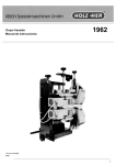
Flush--trimming unit Operating Instructions 1962 Art.--Nr. 209.0538 09/90 1 Contents Page 1 Getting to know the router 3 2 Putting the router unit into service 4 3 Operating the edge banding machine without router 4 4 Fitting the tool 4 4.1 Removing the router bit 4 4.2 Inserting the router bit 6 5 Adjusting and operating the router unit 6 5.1 Flush cutting 6 5.2 Edge surplus cutting 6 6 Turning or changing the reversible tool in the router 8 7 Servicing and care of the router unit 10 8 Troubleshooting 10 9 Specifications 11 10 Tools and accessories 12 2 1 Getting to know the router Bottom router unit Motor (1) Vertical tracer roll (2) Knurled setting screw (3) plus vernier scale Vertical adjuster of router unit with knurled screw (4) plus scale (5) Top router unit Motor (6) Vertical tracer roll (7) Knurled setting screw (8) plus vernier scale Vertical adjuster of router unit with knurled screw (9) plus scale (10) Stand Base (11) Horizontal adjustment of entire unit according to scale (12) 3 2 Putting the unit into service -- Close the guard. -- Switch on the master switch of the edge banding machine. -- Switch on the feed of the edge banding machine. -- Switch on the router unit. Before starting the setting work reset the router so that the stock can enter it without contact for a trial run. All switches are off and secured during setting work. 3 Operating the edge banding machine without router unit -- Undo the clamping bolts (1). -- Retract the router with the spindle (2). -- Tighten the clamping bolts (1). 4 Fitting the tool 4.1 Removing the router bit ----- Undo the bolt (3) and nut (4). Swing away the plate (5). Move out the motor and hang it onto stand. Hold the motor shaft with a WAF 6 spanner and undo the fastening nuts with a WAF 19 hex. spanner. -- Remove the router bit. 4 ! Important! Switch off the master and the unit switches and secure them with a padlock. 5 4.2 Inserting the router -- Insert the router bit with the cutting edge in the direction of the motor arrow. -- Tighten the nut well by applying counter--pres-sure with a spanner. -- Insert the motor. -- Swing the plate (5) and tighten the bolt (3). -- Check the motor position using the scale (6). -- Tighten the nut (4). 5 Direction of rotation in the top and bottom router units against the direction of feed chain operation of the edge banding machine. Adjusting and operating the router unit -- Undo the clamping bolt (1) in each case. -- Set the unit with the spindle (2) in accordance with the scale. -- Tighten the clamping bolt (1). 5.1 Flush cutting -- Tracer rollers are flush when the cutting circle is at scale position »0« -- Correction of bottom router unit at spindle (7) -- Correction of top router unit at spindle (8) 5.2 Edge surplus cutting -- Top edge surplus: adjust the entire router unit with spindle (9) according to the scale. Workpiece + projection * 1,5 mm 6 Top tracer roll not tracing! 7 -- For all settings: Carry out a trial cut, then correct the setting. Edge thickness and permissible feed speed at maximum 3 mm edge surplus. 6 Turning or changing the reversible tool in the router -- Undo the grub screw with 5 Turns of an Allen key. -- Slide the clamping wedge (36) with reversible tool (37) laterally out of the blade groove. -- Turn or change the reversible tool and place it in the groove together with the clamping wedge with the unused cutting edge pointing upwards. -- Place the router bit on steel plate so that the lateral projection of the reversible tool cutter is of the same size. -- Press the top cutting edge of the reversible tool with light finger pressure against the support surface (38 and 39) -- and tighten one grub screw (40) lightly, then both of them in alternate sequence. 8 This is just one example: there are no other makes with slightly different changing methods. Our recommendation: clean all parts well. If both cutting edges are blunted fit a new reversible tool. ! Caution! Cutting edges are sharp! 9 7 Servicing and care of the router unit -- Clean the unit when work is finished. -- Lightly grease moving parts such as sliding surfaces and spindles. -- Check tools for functioning and sharpness. The HOLZ--Her router is maintenance--free. The extractor is highly efficient and the blower nozzle is pneumatically controlled such that it only operates during cutting work. 8 Troubleshooting -- Edge is not completely flush--cut up to the end of stock. 10 1. Stock is not right up against the intake fence -- push it into flush contact. 2. Incorrect positioning of router -- set correctly (see 5). 3. Edges are curved -- too long in storage. 4. Tracer rolls incorrectly set -- readjust the tracer rolls (see 5). 9 Specifications 9.1 Mode of operation -- Top and bottom cutting, conventional -- Verticaly tracing -- Router unit does not swivel 9.2 ------ Working dimensions Edge thickness Edge height Edge surplus Cutting cross--section adjustment of tracer rollers to cutting circle max. 30 mm 66 mm max. 3 mm approx. 90 mm2 -- 1 mm + 6 mm -- Displacement travel of router, horizontal 60 mm 9.3 Drive -- Motor output 2 x 1,86 kW = 3,72 kW -- Motor speed = cutter spindle 12000 min --1 9.4 Connection load of both motors (2 x 1,86 kW = 3,7 kW) -- Motor (2 x 1,86 kW) = (2 x 4,5 A) 9.5 3,7 kW at 220 V, 200 Hz = 12 A Extractor -- Air requirement -- Dynamic pressure -- Connection 700 m3/h (cbm/h) 6--7 mbars 2 x 70 mm 9.6 approx. 85 kg Weight 11 10 Tools and accessories Router -- Steeel body 80 x 30 x 40 -- 1 set of reversible tools carbide-tipped (4 pieces), 40 mm Special accessories: -- Blower nozzle -- Elec. brake -- Counter for tracer roll vert. top and bottom -- Counter for horizontal shifting of assembly -- Pneumatic unit shift device -- Vertical tracer shoe, compl. for overhanging edgings Settings tools: WAF 6 spanner Art. No.: Art. No.: 032.4299 032.4302 Art. No.: Art. No.: 129.6957 129.6183 Art. No.: 209.6129 Art. No.: Art. No.: Art. No.: 131.0895 209.1054 209.1666 -- For router bit change Double--ended open--jaw spanner WAF 17/19 -- For setting the router horizontal and top and bottom router units -- Motor attachment (router bit change or motor arbor adjustment) Crank -- Horizontal adjustment of complete router -- motor adjustment 12 Warranty Our general terms of business shall apply with regard to warranty. Spare parts are available either from your dealer or from the manufacturer. Only genuine HOLZ--HER spare parts may be used in HOLZ--HER machines for warranty reasons. P.O. box address Company address REICH Spezialmaschinen GmbH Postfach 1803 72608 Nürtingen Germany REICH Spezialmaschinen GmbH Plochinger Straße 65 72622 Nürtingen Germany Telephone +49 7022 702--0 Telefax +49 7022 702 101 E--Mail: [email protected] Internet: http://www.holzher.de 13