1
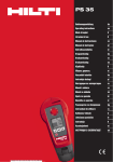
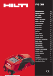
PS 35
Operating instructions
en
ja
ko
zh
cn
Printed: 07.07.2013 | Doc-Nr: PUB / 5137805 / 000 / 00
1
4
5
2
Printed: 07.07.2013 | Doc-Nr: PUB / 5137805 / 000 / 00
6
2
3
1
3
7
38
Printed: 07.07.2013 | Doc-Nr: PUB / 5137805 / 000 / 00
112
ORIGINAL OPERATING INSTRUCTIONS
PS 35 ferrodetector
It is essential that the operating instructions
are read before the tool is operated for the
first time.
Always keep these operating instructions together with the tool.
Ensure that the operating instructions are
with the tool when it is given to other persons.
Contents
Page
1 General information
1
2 Description
2
3 Technical data
5
4 Safety instructions
6
5 Before use
7
6 Operation
7
7 Care and maintenance
9
8 Troubleshooting
10
9 Disposal
10
10 Manufacturer’s warranty
11
11 FCC statement (applicable in US) / ICES
statement (applicable in Canada)
11
12 EC declaration of conformity (original)
12
1 These numbers refer to the corresponding illustrations. The illustrations can be found on the fold-out cover
pages. Keep these pages open while studying the operating instructions.
In these operating instructions, the designation “the tool”
always refers to the PS 35 Ferrodetector.
Parts, operating controls and indicators 1
@ On/off button
; Scan and settings button
= Arrow buttons for navigating in menus
% Status LEDs (red / green)
& Marking opening
( Display
) Battery compartment
1 General information
1.1 Safety notices and their meaning
DANGER
Draws attention to imminent danger that will lead to
serious bodily injury or fatality.
WARNING
Draws attention to a potentially dangerous situation that
could lead to serious personal injury or fatality.
CAUTION
Draws attention to a potentially dangerous situation that
could lead to slight personal injury or damage to the
equipment or other property.
NOTE
Draws attention to an instruction or other useful information.
1.2 Explanation of the pictograms and other
information
Warning signs
General
warning
Symbols
Read the
operating
instructions
before use.
Return waste
material for
recycling.
1
Printed: 07.07.2013 | Doc-Nr: PUB / 5137805 / 000 / 00
en
to it when making an enquiry to your Hilti representative
or service department.
Location of identification data on the tool
The type designation and serial number can be found on
the type identification plate on the tool. Make a note of
this data in your operating instructions and always refer
Type:
Serial no.:
en
2 Description
2.1 Use of the product as directed
The Hilti PS 35 Ferrodetector is designed to detect ferrous metals (steel rebars), non-ferrous metals (copper and
aluminium) and to measure the depth of concrete cover.
The tool is not suitable for locating the position of tensioning cables.
The tool and its ancillary equipment may present hazards when used incorrectly by untrained personnel or when used
not as directed.
Observe the information printed in the operating instructions concerning operation, care and maintenance.
Take the influences of the surrounding area into account. Do not use the tool or appliance where there is a risk of fire
or explosion.
Modification of the tool is not permissible.
2.2 Display
The measurements, settings and tool status are shown in the display.
2.3 Display illumination
The display illumination switches on automatically in conditions of low ambient light.
2.4 Display
Areas of the display
1
@
Status area
2
;
Detection area
Shows the two areas of the display.
2.5 Standard settings in the status area
Standard status area
The standard detection mode is set automatically when the tool is
switched on. In this mode, ferrous metals and non-ferrous metals
(copper and aluminium) can be detected. Limited depth scan is switched
off.
2.6 Status indicator
Status area
@
1
2
3
4
5
;
=
%
&
Shows which status is active
2
Printed: 07.07.2013 | Doc-Nr: PUB / 5137805 / 000 / 00
Ferrous metal detection is active
Non-ferrous metal detection is
active
Limited depth scan is active
Selected depth measurement
range (in mm or inches)
Battery status
2.7 Detection zone
Detection display
@
;
1
Signal strength indicator
Depth measurement in mm or
inches
en
2
Shows the area in the detection zone
2.8 Menus
Menus
1
@
;
2
0
Status area, shows the current
menu settings
Status: 0 is “Off” and I is “On”.
The symbol on the white background is active.
I
Display shown when navigating through the menus.
2.9 Symbols in the display
Ferrous metal
active (left)
inactive (right)
0
I
0
I
Non-ferrous metal
active (left)
inactive (right)
0
I
0
I
Measuring units
inches active (left)
inch
mm
inch mm
inch mm
Limited depth scan (mm)
mm active (right)
active (left)
inactive (right)
0 25 50 75
0 25 50 75
Limited depth scan (inches)
active (left)
inactive (right)
0 1 2 3
0 1 2 3
3
Printed: 07.07.2013 | Doc-Nr: PUB / 5137805 / 000 / 00
Audible signal
active (left)
inactive (right)
0
en
I
0
I
User training
active (left)
?
0
?
I
0
inactive (right)
I
2.10 Warnings and error symbols in the display
Error message
Contact Hilti service
Temperature warning
Inadmissible operating range
Electromagnetic interference
Too much interference from the surroundings
Calibration warning
Calibration is required
2.11 Battery condition indicator
Number of segments shown
Charge status in %
3
= 100 % capacity
2
=80 % capacity
1
= 50 % capacity
0
= 20 % capacity
Battery symbol blinks
= fully discharged
2.12 Items supplied as standard
1
Tool
4
Batteries
1
1
1
1
2
Hand strap
Operating instructions
Manufacturer’s certificate
Soft pouch
Markers
4
Printed: 07.07.2013 | Doc-Nr: PUB / 5137805 / 000 / 00
3 Technical data
Right of technical changes reserved.
NOTE
All values apply to individual rod-like metal objects positioned at right angles to the direction of movement of the
detector and when the surface of the concrete is flat and smooth with no external interference factors. Detection range
and accuracy is reduced when measurements are taken on brickwork.
PS 35
Detection range for locating ferrous metals in concrete
(individual rebars)
Detection range for locating non-ferrous metals (copper
and aluminium pipes)
Depth measurement range for individual rebars
Accuracy of depth measurement (accurate measurement mode)*
Localization accuracy
Minimum distance between objects
Power source
>∅ 8 mm (≧ # 3): 5…120 mm (¼ in ...4¾ in)
∅ 6…8 mm: 5…100 mm (¼ in ... 4 in)
Diameter Min. 10 mm (½ in), Wall thickness Min. 2 mm
(³/₃₂ in): 5…80 mm (¼ in ...3¹/₈ in)
>∅ 8 mm (≧ # 3): 5…120 mm (¼...4¾ in)
∅ 6…8 mm: 5…100 mm (¼ ... 4 in)
Depth range 5…60 mm (¼ in ... 2²/₃ in): ±3 mm (±¹/₈ in)
Depth range 60…80 mm (2²/₃ in ... 3¹/₈ in): ±5 mm (±¼
in)
Depth range 80…100 mm (3¹/₈ ... 4 in): ±7 mm (±⁹/₃₂ in)
Depth range 100…120 mm (4 in ... 4³/₄ in): ±11 mm
(±⁷/₁₆ in)
±10 mm (±½ in)
Depth range 5…55 mm (¼ in ...2¹/₈ in): 55 mm (2¹/₈ in)
Depth range ≥ 55 mm (2¹/₈ in): Distance/depth factor
>1.5
4x1.5V (AAA) LR03 alkaline batteries
Battery life at 20 °C
8h
Operating temperature range
-15…+50°C (5° F ... 122° F)
Automatic cut-out
5 min
Storage temperature range (dry)
-25…+63°C (-13° F ... 145° F)
Relative air humidity
95%
Protection class
IP 54 (protection against dust and water spray)
Weight (including batteries)
450 g (1 lb)
Dimensions (L x W x H)
237 mm x 104 mm x 47 mm (9.4 in x 4 in x 2 in)
NOTE
* Applies to concrete with typical aggregate and reinforcement content.
Measuring units
mm
Dimensions
Millimeters
In
Inches
in ¹⁄₈
¹⁄₈ fraction
5
Printed: 07.07.2013 | Doc-Nr: PUB / 5137805 / 000 / 00
en
4 Safety instructions
en
In addition to the information relevant to safety given
in each of the sections of these operating instructions,
the following points must be strictly observed at all
times.
The tool is designed to detect ferrous metals (steel rebars) and non-ferrous metals (copper and aluminium)
in concrete, brick, drywall and under plaster surfaces
in accordance with the information provided in the
technical data section.
4.1 Basic information concerning safety
a)
b)
c)
d)
e)
f)
g)
h)
i)
j)
k)
l)
m)
n)
o)
p)
q)
r)
s)
t)
u)
Do not render safety devices ineffective and do
not remove information and warning notices.
Keep children away from the tool.
Check that the tool functions correctly each time
before use.
Check the display after switching the tool on. The
display should show the Hilti logo, the tool model
designation and version. The tool then carries out a
brief self-test, after which the standard settings or
the previously saved settings are displayed.
Check to ensure that the tool is able to calibrate
itself after switching on.
Operation of the tool in the proximity of pregnant
women is not permissible.
Rapidly changing detection conditions may lead to
inaccurate readings.
Use the tool only within the specified conditions.
Do not use the tool on materials containing items
such as tensioning cables or stainless steel objects.
Do not use the tool in the proximity of medical
instruments and appliances.
Do not drill at positions where the tool has located
an object.
The warnings shown in the display must always
be observed.
Do not use the tool for quality control inspections.
Do not use the tool in the proximity of sources of
electromagnetic interference (e.g. electric breakers in operation).
Take the influences of the surrounding area into
account. Do not use the tool where there is a risk
of fire or explosion.
Use of the tool in the proximity of persons with a
cardiac pacemaker is not permissible.
Make sure that the display area can be easily
read (e.g. do not touch the display area with the
fingers, keep the display area clean).
Do not use the tool if it is defective.
Always keep the detection area clean.
Always check how the tool is set before using it.
The accuracy of the tool is influenced by the base
material. If the tool is unable to calibrate itself correctly, small measurement errors may result.
When the tool is unable to calibrate itself automatically, a warning appears in the display.
6
Printed: 07.07.2013 | Doc-Nr: PUB / 5137805 / 000 / 00
4.2 Proper organization of the workplace
Avoid unfavorable body positions when working
on ladders or scaffolding. Make sure you work
from a safe stance and stay in balance at all
times.
b) When the tool is brought into a warm environment
from very cold conditions, or vice-versa, allow it
to become acclimatized before use.
c) Use the tool only within its specified limits.
d) Observe the accident prevention regulations applicable in your country.
a)
4.3 Electromagnetic compatibility
Although the tool complies with the strict requirements of
the applicable directives, Hilti cannot entirely rule out the
possibility of the tool being subject to interference caused
by powerful electromagnetic radiation, leading to incorrect operation. Check the accuracy of the tool by taking
measurements by other means when working under such
conditions or if you are unsure. Likewise, Hilti cannot rule
out the possibility of interference with other devices (e.g.
aircraft navigation equipment). The tool complies with the
requirements of class A; The possibility of interference
occurring in a domestic environment cannot be excluded.
4.4 General safety instructions
Check the condition of the tool before use. If the
tool is found to be damaged, have it repaired at a
Hilti service center.
b) The user must check the accuracy of the tool
after it has been dropped or subjected to other
mechanical stresses.
c) Although the tool is designed for the harsh conditions of jobsite use, as with other measuring
instruments it should be treated with care.
d) Although the tool is protected to prevent entry
of dampness, it should be wiped dry each time
before being put away in its transport container.
e) Check to ensure that all symbols are visible when
the tool is switched on.
f) Check the accuracy of the tool before using it for
detection or measurement.
a)
4.5 Electrical safety
a) Keep the batteries out of reach of children.
b) Do not allow the batteries to overheat and do not
expose them to fire. The batteries may explode or
release toxic substances.
c) Do not charge the batteries.
d) Do not solder the batteries into the tool.
e) Do not discharge the batteries by short-circuiting.
This may cause them to overheat and present a risk
of personal injury (burns).
f) Do not attempt to open the batteries and do not
subject them to excessive mechanical stress.
4.6 Transport
Always remove the batteries before shipping the tool.
5 Before use
2.
5.1 Inserting the batteries 2
3.
5.3 Switching the tool on / off
CAUTION
Do not use damaged batteries.
1.
CAUTION
Always replace the complete set of batteries.
2.
DANGER
Do not mix old and new batteries. Do not mix batteries
of different makes or types.
1.
2.
3.
Open the battery compartment.
Remove the batteries from the packaging and insert
them in the tool.
NOTE Take care to observe correct polarity (see
symbols in battery compartment).
Check to ensure that the battery compartment cover
is closed correctly.
5.2 Checking the tool
1.
Check to ensure that the sensor area is not damp. If
necessary, use a cloth to dry the sensor area.
For accurate results, allow the tool to acclimatize
itself to the ambient conditions before use if it has
previously been exposed to extreme temperature
fluctuations.
Check how the tool is set before using it.
Switch the tool on by pressing the on/off button.
After switching the tool on, the standard settings are
active.
When the tool is already switched on, press the
on/off button: the tool switches itself off.
NOTE If the tool is not used or an error message
is displayed, it switches itself off automatically after
five minutes. The tool switches itself off when the
batteries are discharged.
5.4 Settings menu
1.
2.
3.
4.
5.
Switch the tool on.
Press one of the arrow buttons (right or left) to go to
the settings menu.
Press one of the arrow buttons to move through the
menu and make your selection.
Press the scan and settings button to change the
settings.
After making your selection, the tool will automatically return to the area display within 5 seconds and
is then ready for operation.
NOTE If no selection is made within 5 seconds, the
tool leaves the settings menu automatically.
6 Operation
2.
6.1 Preparing the tool for use
CAUTION
Always drill at a safe distance from objects you have
detected.
1.
Before switching the tool on, check that it is not in
contact with anything and is clear of the working
surface or metal objects.
3.
Switch the tool on by pressing the on/off button.
After carrying out a brief self-test, the tool begins to
calibrate itself automatically. The status LEDs light
green as soon as this has been completed.
While the tool is calibrating itself, hold it in the air at
least 30 cm (12 in) away from any metal objects and
away from the surface on which you are working.
The first five times the tool is switched on, it runs
through an animated training program that demonstrates how it should be used. This training program
can be switched off in the options in the settings
menus.
7
Printed: 07.07.2013 | Doc-Nr: PUB / 5137805 / 000 / 00
en
imum when the tool is positioned over the center of
the object.
In the meantime, the depth measurement is shown
in the display.
If the tool is moved further until it is past the ferrous
metal, the status LEDs light green and the signal
strength indicator shows a decreasing value.
To obtain an exact indication of the position of the
object, the tool must be moved back in the opposite
direction until the status LEDs light red and the
signal strength indicator shows the maximum value.
Use the marking pen supplied to mark the position
of the ferrous metal object through the marking
opening in the tool.
If the loudspeaker has been activated, a constant
audible signal is emitted so long as the tool is
positioned over the ferrous metal object.
When the tool approaches a non-ferrous metal object (copper, aluminium), the “non-ferrous metal”
symbol begins to blink, the status LEDs light red
and the amplitude of the signal strength indicator
rises and reaches its maximum when the tool is
positioned over the center of the object.
If the tool is moved further until it is past the nonferrous metal object, the status LEDs light green and
the signal strength indicator shows a decreasing
value.
To obtain an exact indication of the position of the
object, the tool must be moved back in the opposite
direction until the status LEDs again light red and
the signal strength indicator shows the maximum
value.
Use the marking pen supplied to mark the position
of the non-ferrous metal object through the marking
opening in the tool.
If the loudspeaker has been activated, a constant
audible signal is emitted so long as the tool is
positioned over the non-ferrous metal object.
6.2 Working with the tool
en
Check that the tool makes full contact with the surface
you wish to scan.
Use the tool only on smooth surfaces.
Bring the tool slowly and carefully into contact with the
surface to be scanned.
Do not move the tool at a speed greater than 20 cm/s (9
in/s).
6.2.1 Sweep scan method
In order to achieve best results, the tool should be used
with a sweeping motion (extended horizontal and vertical
movements over the object). The series of illustrations
show the sweep method in use. When the tool is switched
on for the first time, it displays an animated training
program that shows how the tool should be used to scan
a surface.
6.3 Locating objects in standard mode
6.4 Locating objects consisting solely of ferrous
metal
1.
2.
Switch the tool on and hold it at least 30 cm (12
in) away from any metal objects and away from the
surface on which you are working.
The tool activates standard mode after completing
automatic calibration.
The depth measurement units (mm or in) are shown
in the display and the status LEDs light green.
The tool is ready to be used for locating objects.
Carefully bring the tool into contact with the surface
to be scanned and then begin to move it sideways.
NOTE Deactivate the limited depth scan setting
if you wish to detect ferrous metal without depth
limitation.
When the tool approaches a ferrous metal object (a
rebar), the “ferrous metal” symbol begins to blink,
the status LEDs light red and the amplitude of the
signal strength indicator rises and reaches its max-
8
Printed: 07.07.2013 | Doc-Nr: PUB / 5137805 / 000 / 00
1.
2.
3.
Switch the tool on.
Activate the ferrous metals detection mode in the
menus and deactivate the non-ferrous metals detection mode.
The limited depth scan mode may be activated if
desired.
Then follow the steps described in the section “Locating objects in standard mode” (for ferrous metals).
6.5 Locating objects consisting solely of
non-ferrous metal
1.
2.
2.
Switch the tool on.
Activate the non-ferrous metal detection mode in the
menus and deactivate the ferrous metal detection
mode.
The limited depth scan mode is deactivated automatically.
Follow the steps described in the section “Locating
objects in standard mode” (for non-ferrous metal).
6.6 Precise rebar depth measurement.
NOTE
The precise depth measurement mode can be used only
with reinforcing bars in concrete.
3.
Carefully bring the tool into contact with the surface
to be scanned and then begin to move it slowly
sideways.
When the tool approaches a rebar, the “ferrous
metal” symbol begins to blink, the status LEDs light
red and the amplitude of the signal strength indicator rises and reaches maximum when the tool is
positioned over the center of the rebar. If the tool
is moved further until it is past the rebar, the status
LEDs light green and the signal strength indicator
shows a decreasing value. To obtain an exact indication of the position of the rebar, the tool must be
moved back in the opposite direction until the status
LEDs again light red and the signal strength indicator
shows the maximum value. When the tool is in the
area where maximum signal strength is indicated,
the initial depth measurement is displayed.
At this point, press the “scan” button and the precise
depth measurement will then be displayed within
two to three seconds.
6.7 Limited depth scan
NOTE
This measurement mode allows rebars to be located
within a specified depth range.
NOTE
When using the tool in this mode, the preset depth must
take a clearance distance from the rebar into account.
1.
2.
1.
Switch the tool on.
Activate the ferrous metals detection mode in the
menus and deactivate the non-ferrous metals detection mode.
3.
4.
Switch the tool on.
In the settings menu, select “ferrous metals” and set
the desired depth scan range in which you wish to
locate the rebars. If necessary, you can deactivate
the non-ferrous metals localization function.
Press the “scan” button to select the desired maximum depth range (25, 50 or 75 mm; 1, 2 or 3
in).
Use the tool as described in the section “Detecting
objects in standard mode” for ferrous metals. In this
scanning mode, only objects located at a depth less
than the preset measuring depth will be detected.
The last setting is memorized by the tool.
7 Care and maintenance
7.1 Cleaning and drying
1.
2.
Use only a clean, soft cloth for cleaning. If necessary,
moisten the cloth slightly with pure alcohol or a little
water.
NOTE Do not use any other liquids as these may
damage the plastic components.
The temperature limits for storage of your equipment
must be observed, especially in winter / summer.
7.2 Storage
Remove the tool from its case if it has become wet.
The tool, its carrying case and accessories should be
cleaned and dried (at maximum 40°C / 104°F). Repack
the equipment only once it is completely dry.
Check the accuracy of the equipment before it is used
after a long period of storage or transportation.
Remove the batteries from the tool before storing it for a
long period. Leaking batteries may damage the tool.
7.3 Transport
Use the Hilti toolbox or packaging of equivalent quality for
transporting or shipping your equipment. Make sure that
the tool is held securely in place inside the Hilti toolbox
9
Printed: 07.07.2013 | Doc-Nr: PUB / 5137805 / 000 / 00
en
or equivalent packaging during transport. Store the tool
safely.
CAUTION
Always remove the batteries before shipping the tool.
en
7.4 Hilti calibration service
We recommend that the tool is checked by the Hilti calibration service at regular intervals in order to verify its
reliability in accordance with standards and legal requirements.
Use can be made of the Hilti calibration service at any
time, but checking at least once a year is recommended.
The calibration service provides confirmation that the
tool is in conformance, on the day it is tested, with the
specifications given in the operating instructions.
The tool will be readjusted if deviations from the manufacturer’s specification are found. After checking and
adjustment, a calibration sticker applied to the tool and
a calibration certificate provide written verification that
the tool operates in accordance with the manufacturer’s
specification.
Calibration certificates are always required by companies
certified according to ISO 900x.
Your local Hilti Center or representative will be pleased
to provide further information.
8 Troubleshooting
Fault
Possible cause
Remedy
The tool can’t be switched on.
The battery is exhausted.
Replace the battery.
Insert the battery correctly.
The tool can’t calibrate itself.
The battery is inserted the wrong way
round (incorrect polarity).
The battery compartment is not
closed.
The tool is too close to metal objects.
The tool displays an electromagnetic interference warning.
The tool is too close to electromagnetic interference.
Switch the tool off and then hold it
at least 30 cm (12 in) away from any
metal objects and away from the surface on which you are working before
switching it on again.
Keep the tool away from sources of
electromagnetic interference.
The tool displays a temperature
warning.
The temperature is too high or too
low.
Observe the operating temperature
range (technical data).
No indication when positioned
over an object.
The ferrous / non-ferrous metal mode
is not active.
Activate the desired detection mode.
Close the battery compartment.
9 Disposal
Most of the materials from which Hilti tools or appliances are manufactured can be recycled. The materials must be
correctly separated before they can be recycled. In many countries, Hilti has already made arrangements for taking
back old tools or appliances for recycling. Ask Hilti Customer Service or your Hilti representative for further information.
10
Printed: 07.07.2013 | Doc-Nr: PUB / 5137805 / 000 / 00
For EC countries only
Do not dispose of electronic measuring tools or appliances together with household waste.
In observance of the European Directive on waste electrical and electronic equipment and its implementation in accordance with national law, electric tools and batteries that have reached the end of their
life must be collected separately and returned to an environmentally compatible recycling facility.
10 Manufacturer’s warranty
Hilti warrants that the tool supplied is free of defects in
material and workmanship. This warranty is valid so long
as the tool is operated and handled correctly, cleaned
and serviced properly and in accordance with the Hilti
Operating Instructions, and the technical system is maintained. This means that only original Hilti consumables,
components and spare parts may be used in the tool.
This warranty provides the free-of-charge repair or replacement of defective parts only over the entire lifespan
of the tool. Parts requiring repair or replacement as a
result of normal wear and tear are not covered by this
warranty.
Additional claims are excluded, unless stringent national rules prohibit such exclusion. In particular, Hilti
is not obligated for direct, indirect, incidental or consequential damages, losses or expenses in connection with, or by reason of, the use of, or inability to
use the tool for any purpose. Implied warranties of
merchantability or fitness for a particular purpose are
specifically excluded.
For repair or replacement, send the tool or related parts
immediately upon discovery of the defect to the address
of the local Hilti marketing organization provided.
This constitutes Hilti’s entire obligation with regard to
warranty and supersedes all prior or contemporaneous
comments and oral or written agreements concerning
warranties.
11 FCC statement (applicable in US) / ICES statement (applicable in Canada)
NOTE
Changes or modifications not expressly approved by Hilti
could void the user’s authority to operate the equipment.
Operation is subject to the following two conditions:
1. This device may not cause interference not in compliance with the standards.
2. This device must accept any interference received, including interference that may cause undesired operation.
PS 35 01
Hilti=trademark of Hilti Corp., Schaan, LI
Made in Malaysia
This device complies with part 15 of the FCC Rules. Operation is subject to the condition that this device does not cause
harmful interference. This Class B digital apparatus complies with Canadian ICES-003. Cet appareil numérique de la classe B
est conforme à la norme NMB-003 du Canada.
Power: 6V/160 mA
Item No.:
Serialnumber:
402292
This device complies with section 15 of the FCC standards and fulfills the IC requirements in accordance with
ICES-003 for class B.
11
Printed: 07.07.2013 | Doc-Nr: PUB / 5137805 / 000 / 00
en
12 EC declaration of conformity (original)
Designation:
Ferrodetector
Type:
en
PS 35
Year of design:
2009
We declare, on our sole responsibility, that this product
complies with the following directives and standards:
2011/65/EU, 2006/95/EC, 2004/108/EC, EN ISO 12100.
Hilti Corporation, Feldkircherstrasse 100,
FL‑9494 Schaan
Paolo Luccini
Head of BA Quality and Process Management
Business Area Electric Tools & Accessories
01/2012
12
Printed: 07.07.2013 | Doc-Nr: PUB / 5137805 / 000 / 00
Matthias Gillner
Executive Vice President
Business Area Electric
Tools & Accessories
01/2012
Technical documentation filed at:
Hilti Entwicklungsgesellschaft mbH
Zulassung Elektrowerkzeuge
Hiltistrasse 6
86916 Kaufering
Deutschland
Hilti Corporation
Printed: 07.07.2013 | Doc-Nr: PUB / 5137805 / 000 / 00
409101 / A3
409101
Hilti = registered trademark of Hilti Corp., Schaan
W 3655 | 0313 | 10-Pos. 2 | 1
Printed in Germany © 2013
Right of technical and programme changes reserved S. E. & O.
*409101*
LI-9494 Schaan
Tel.: +423 / 234 21 11
Fax:+423 / 234 29 65
www.hilti.com