1
General Description • Mounting • Connection
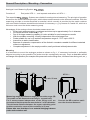
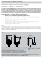
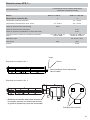
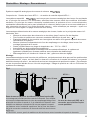
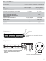
The analogue probe consists of a reference system (R) at the top of the probe to determine the existing
material characteristics. This reference range stretches over 85 mm independent of type. Then follows the
actual analogue measuring range (M) customer specified, but with regard to the total length (L).The inactive
range (IB), a minimum of 50 mm, serves to mount the probe. The mounting can also be a metallic holder. The
holder has to be fixed at the inactive area with maintenance of the minimum distance (fig. 2).
Fig.2
Reference system (R) • Measuring range (M) • Non-active range (IB) • Total length (L)
The measuring range (M) of the probe must be mounted in a range of the container without change in
diameter of the cross section in order to guarantee the linearity of the output signal. Changes in cross
section lead to non-linearity, due to conductive installations such as wipers for example.
The reference system (R) does not require a constant cross section of the container. Thus it can project
into the cone of the container.
It is possible to mount the probe in a 30° angle to the vertical, taking into account that the smallest side distance
to the container wall is not less then 50 mm.
The probe should not be mounted in the filling area. For a measurement which is independent of the filling cone
it is recommended to mount the probe at 1/4 of the container diameter (Fig. 1, page 11).
The probe can be mounted with Rechner’s mounting devices (see accessories) or with customers own mounting
devices.
The inactive area (IB) from the end of the measuring range to the container cover (if metal) should be 1/3 of the
container diameter or min. 50 mm in order to prevent non-linearity (Fig. 1 page 11).
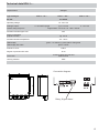
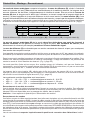
The available evaluation units are:
• Analogue output KFA-1-...UL-KL = Voltage 0...10 V DC
• Analogue output KFA-1-...IL4-KL = Current 4...20 mA
• Analogue output KFA-1-...-FL-KL = Frequency 0...10 kHz
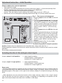
Connection of the evaluation unit:
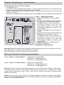
The connection of the supply voltage has to be made according to the diagram on the unit. To connect the unit,
one has to open the four bayonet screws on the cover. The connection is made with clamp terminals. The wiring
can be fed into the housing via 4 PG 9 screwings. Pay attention to the correct supply voltage.
Connection of the probe:
The probe is connected via the standard coaxial cable. The probe cable is ready-made for connection on
delivery. The insulation of the coaxial cable should not be damaged and the shield should not come into
contact with the PE / protective conductor BE container potential. Shortening or lengthening the probe
cable is not recommended. Please contact RECHNER-Sensors should alterations of the probe cable be
inevitable.
For an interference-free operation the wiring of the coaxial cable should be separate from the electric
power cable. When making the connection, please make sure that the colour markings white/black are
correctly assigned!
12