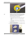
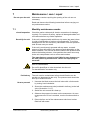
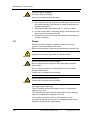
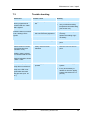
1
Operating Instructions
TECHSPAN
Elmasteam y ES 3000 y ES 5000
CAUTION! Read and observe the operating instructions before you operate
the unit.
.
TECHSPANGROUP
Australia Tel. 1-800 148 791
www.techspanonline.com
New Zealand Tel. 0800 603 603
Content
2
1
General.............................................................................. 3
2
Important safety warnings ................................................. 3
2.1 Description of safety warnings on the unit .................. 5
3
Product description............................................................ 7
3.1 Delivered equipment and accessories ........................ 7
3.1.1 Elmasteam 3000 .................................................. 7
3.1.2 Elmasteam 5000 .................................................. 7
3.2 CE conformity ............................................................. 7
3.3 Functioning ................................................................. 7
3.4 Safety devices............................................................. 8
3.5 Technical details ......................................................... 8
3.6 Description elements top view .................................... 9
3.7 Description elements front view ................................ 10
3.8 Description function switch ....................................... 11
3.9 Description safety temperature switch ...................... 12
3.10 Description LED operating display............................ 13
3.11 Description elements back view................................ 14
3.12 Operation of the fixed nozzle .................................... 15
3.13 Operation of the flexible hand piece ......................... 15
4
Initial operation ................................................................ 16
4.1 Placement and ambient conditions ........................... 16
4.2 Mounting of fixed nozzle (optional) ........................... 17
5
Filling of the unit .............................................................. 18
5.1 Filling by hand........................................................... 18
5.2 Automatic filling with pump (optional) ....................... 19
5.2.1 Connection the pump at the tap water supply .... 20
5.2.2 Connection the pump at a water tank................. 21
6
Handling during operation ............................................... 23
6.1 Working with the hand piece..................................... 24
6.2 Working with the fixed nozzle ................................... 24
6.3 Operation with compressed air (optional) ................. 25
6.4 Operation with wet steam (optionally ES 5000) ........ 26
7
Maintenance / care / repair.............................................. 27
7.1 Monthly maintenance works ..................................... 27
7.2 Repair ....................................................................... 28
7.3 Trouble shooting ....................................................... 29
8
Putting out of action and waste disposal ......................... 30
9
Manufacturer’s contact address ...................................... 30
TECHSPANGROUP
Australia Tel. 1-800 148 791
New Zealand Tel. 0800 603 603
General
1
General
The present Operating Instructions are part of the delivered
equipment. They must be ready for use at any time and remain
with the unit in case of resale.
We reserve the right to carry out technical modifications on the
unit due to advanced development.
The copyright remains with the editor.
These Operating Instructions are not automatically revised. For
the latest revised issue please contact the manufacturer and
editor of these Operating Instructions.
The manufacturer’s contact address is indicated on the last page
of the Operating Instructions.
2
Important safety warnings
Read carefully before initial operation!
Use the Elmasteam steam jet cleaner according to the Operating
Instructions. In case of improper use the manufacturer cannot be
held responsible for the safety of the operating personnel and the
correct functioning of the unit.
Intended use
The present steam jet cleaner has been designed for the
cleaning of items only. Do not steam clean living beings!
Operation by industrial and commercial businesses only!
Check for transport
damages
After unpacking check the unit for possible transport damages. In
case of visible damages do not put the unit into operation.
Contact your supplier and forwarding agent.
Mains connection
For safety reasons, the present unit must be connected to a
correctly grounded socket only. The technical details indicated on
the nameplate must correspond with the available mains
connection details, in particular those of the mains voltage and
current connected value.
Placement
Place the unit at a dry and sufficiently ventilated workplace. Keep
the unit dry!
Operating personnel
Caution! Hot surfaces
3
For safety reasons, the steam jet unit must be operated by
authorized and sufficiently instructed personnel only. The unit
must not be operated by unauthorized persons or by children.
During operation, the unit cover, the steam outlet nozzle and the
drain plug heat up considerably.
TECHSPANGROUP
Australia Tel. 1-800 148 791
New Zealand Tel. 0800 603 603
Important safety warnings
Caution! Hot steam
Wrong operation may cause a risk of scalding by hot steam!
Unauthorized third persons must not stay within reach of the
steam jet. Be careful when operating the unit in order to prevent
injuries caused by hot steam.
Switch the unit into „stand-by“ operating mode during operating
breaks. This prevents unintended activation of the steam outlet.
Do not open the screw cap of the filling duct of the pressure tank
with a pressure exceeding 0 bar.
If the switch is turned to „steam outlet“ steam is immediately
produced at the nozzle or at the hand piece without pressing any
additional key. For the operation mode „steam outlet“ the hand
piece must be fastened safely, e.g. in the hand piece holder.
Ensure that the released steam does not endanger staff or
equipment.
Prevention of
electrical accidents
In order to prevent electrical accidents and damage, do not
steam clean the unit and do not let any liquid enter the unit.
In case of any damage on the unit or if the unit has become wet
pull the mains plug.
The unit must be opened by authorized specialized personnel
only. Pull the mains plug before opening the unit.
Do not operate the unit if a mains cable or important components
of the unit, e.g. safety devices, steam nozzle, are damaged.
If you use an extension cord ensure that plug and coupling are
waterproof.
Caution: an unsuitable extension cord may be dangerous.
Filling
No chemical
additions
Noise emission
Maintenance and
repair
Do not operate the Elmasteam with empty water tank as this
might cause damage to the unit!
Operate the unit with water only.
Steam jet cleaners can produce an uncomfortable noise during
operation. Use your personal ear protection device when in close
proximity to an operating unit.
Carry out the maintenance works at regular intervals as
described in the present Operating Instructions in order to
guarantee the correct functioning of the unit and to keep the
safety standard (see section 7).
Repair must be carried out by authorized specialized personnel
only. Pull the mains plug before opening the unit.
Always pull the mains plug before you open the unit or carry out
any maintenance work.
High-pressure hoses, facilities and coupling pieces are important
safety components. Use high-pressure hoses, facilities and
coupling pieces recommended by the manufacturer only.
In case of damage or faulty operation please contact your
supplier or the manufacturer of the unit.
4
TECHSPANGROUP
Australia Tel. 1-800 148 791
New Zealand Tel. 0800 603 603
Important safety warnings
2.1
Description of safety warnings on the unit
Caution: When operated improperly, high-pressure jets may be
dangerous. Do not aim the jet toward persons, live electric
equipment or the unit itself. Do not aim the jet toward yourself or
other persons for cleaning of clothing or shoes.
Caution: Do not open the ball valve with heated unit and with an
overpressure in the pressure tank exceeding 0 bar (observe
manometer).
Exception: maintenance works (see section 7).
Caution: Hot surfaces!
TECHSPANGROUP
Australia Tel. 1-800 148 791
New Zealand Tel. 0800 603 603
Important safety warnings
Note (only for units with optional compressed air feed duct):
The connected compressed air supply must not exceed a
pressure of 6 bar. Risk of damage to parts inside the unit.
Note (only for units with optional water pump):
The maximum water pressure must not exceed 4 bar. Risk of
damage to parts inside the unit.
6
TECHSPANGROUP
Australia Tel. 1-800 148 791
New Zealand Tel. 0800 603 603
Product description
3
Product description
3.1
Delivered equipment and accessories
3.1.1
3.1.2
Elmasteam 3000
•
basic unit with a tank volume of 3 litres
•
fixed nozzle or flexible hand piece (both optional)
•
compressed air connection (inlet) (optional)
•
filling funnel
•
pincette
•
maintenance tube “M“ for monthly maintenance
Elmasteam 5000
As Elmasteam 3000, but with a tank volume of 5 litres and with 2
optional outlets for fixed nozzle and / or flexible hand piece.
3.2
•
compressed air connection (inlet) (optional)
•
wet steam (optional)
CE conformity
The present Elmasteam steam jet cleaner is in compliance with
the CE marking criteria and the following EC directives:
2006/95/EG Low voltage directive
2004/108/EG EMC directive
The declaration of conformity is available from the manufacturer.
3.3
Functioning
Pressure generation
Steam outlet
Wet steam
Water for steam
generation
TECHSPANGROUP
In a safety pressure tank, filled by hand or automatically, the
water is heated by means of a powerful heating element up to a
temperature of 173 °C. In the process, a steam pressure of
approx. 8 bar is created.
The steam can be let out through the nozzle(s).
Optional on ES 5000. Steam and hot water from the pressure
tank are mixed. The ratio of mixture is variable via control valve.
Tap water of standard water hardness or distilled water. If the
unit is used with pump, the value of conductance must be at least
15 μS.
Australia Tel. 1-800 148 791
New Zealand Tel. 0800 603 603
Product description
3.4
Safety devices
The Elmasteam steam jet cleaners are equipped with all required
safety devices, such as:
•
•
•
•
•
3.5
Safety pressure relief valve
Safety pressure tank closing cap, prevents opening of screw
cap of filling duct by mistake
Safety temperature control
Electric contacts are protected against splash water
Low voltage (24 V) in flexible hand piece
Technical details
Elmasteam 3000
Elmasteam 5000
120 or 230
230 - 240
50 / 60
50 / 60
shockproof plug
1 phase
USA: grounded
NEMA 5-20 plug
Shockproof plug
1 phase
USA: grounded
NEMA 6-15 plug
Mains impedance max.
(Ohm)
0.155
0.155
Power max. (W)
1790
2950
Current consumption max.
(A) 115 V / 230V
15.5 / 7.8
12.8
Required mains fuses (A)
115 V / 230 V
20 / 10
16
Protection grade basic unit
IPX3
IPX3
Protection grade hand piece
IPX4
IPX4
Sound pressure level at 8
bar (dBA)
93
93
Steam pressure in pressure
tank (bar)
8
8
Pressure tank volume (lit.)
3
5
2.6
4.7
Steam temperature at outlet
approx. 160 C°
approx. 160 C°
Housing dimensions with
feet W x D x H (mm)
338 x 260 x 296
338 x 260 x 391
Units overall dimensions w.
hand piece support + fixed
nozzle W x D x H (mm)
385 x 445 x 330
385 x 445 x 420
stainless steel
stainless steel
approx. 16
approx. 20
Mains voltage (Vac)
Mains frequency (Hz)
Mains connections
Max. filling volume (litre)
Housing material
Weight incl. foot-activated
switch (kg)
8
TECHSPANGROUP
Australia Tel. 1-800 148 791
New Zealand Tel. 0800 603 603
Product description
3.6
Description elements top view
C
A
D
B
Illustration 3.6: Unit top view (here ES 3000)
A
Screw cap of pressure tank: filling duct for manual filling
B
Collecting rim for water spilled during filling
C
Ventilation openings
D
Handles
TECHSPANGROUP
Australia Tel. 1-800 148 791
New Zealand Tel. 0800 603 603
Product description
3.7
Description elements front view
A
D
B
B
C
F
E
G
Illustration 3.7 View unit front (here ES 5000)
A
Function switch
Description see section 3.8..
B
Connection socket (only on ES 5000) for the optional
connection of a fixed nozzle on model with 2 fixed nozzles.
C
Connection socket for the connection of the fixed nozzle on ES
3000.
ES 5000 on model with 1 fixed nozzle.
D
Pressure manometer
Display of steam pressure in the pressure tank (bar). As soon as
a pressure of 8 bar is reached the unit is ready of operation.
10
E
LED Operating mode display
Description see section 3.11.
F
Support for flexible hand piece (optional).
G
Safety temperature limit: description see section 3.9.
TECHSPANGROUP
Australia Tel. 1-800 148 791
New Zealand Tel. 0800 603 603
Product description
3.8
Description function switch
Illustration 3.8. function switch
off
steam outlet
If the switch is turned to „off“ the unit is switched off completely.
This switch position is for the release of the residual steam
pressure (before opening the tank closing screw cap).
Caution! Steam is immediately released from the nozzle
without pressing any additional key.
On the ES 5000 the steam escapes as follows:
• with combination of fixed nozzle / flexible hand piece > fixed
nozzle
• with combination of fixed nozzle / fixed nozzle > left fixed
nozzle
• with combination of flexible hand piece / flexible hand piece >
left hand piece
For the operation mode „steam outlet“ the hand piece must
be fastened safely, e.g. in the hand piece holder. Ensure that
the released steam does not endanger staff or equipment.
Standby
Recommended operating mode during idle phases. This mode
prevents unintended activation of the steam release. The tank
pressure remains the same. The unit is ready for operation
immediately upon turning the switch to position “on“.
steam on
If the switch is turned to „on“ the steam release at the outlet can
be activated (with pressing additional key).
TECHSPANGROUP
Australia Tel. 1-800 148 791
New Zealand Tel. 0800 603 603
Product description
3.9
Description safety temperature switch
The safety temperature switch is released when the minimum
filling level (min. water) in the pressure tank is reached; it
automatically cuts off the heating of the Elmasteam. There is an
additional visual signal (LED min. water) and an acoustic alert
signal. When the unit has been refilled the safety temperature
limit must be reset by hand in order to allow further operation of
the unit.
To reset the malfunction indication by hand, unscrew the cover
(anti-clockwise) (see illustration 3.9.1.) and press the green
button of the safety temperature switch (see illustration 3.9.2.).
Caution! A reset of the safety temperature limit without refilling
of the pressure tank may destroy the heating.
Bild 3.9.1. safety temperature switch with cover
Bild 3.9.2. green button to reset the alarm
12
TECHSPANGROUP
Australia Tel. 1-800 148 791
New Zealand Tel. 0800 603 603
Product description
3.10
Description LED operating display
llustration 3.10 LED Operating display (here model with pump)
ready
heating
min. water
I
turns on as soon as the pressure tank operating pressure is
reached and the unit is ready for operation.
is on during heating up of the unit.
turns on as soon as the minimum filling level in the pressure tank
is reached and the tank must be refilled. There is also an
acoustic alert signal.
Restart after min. water alarm is only possible after resetting the
safety temperature limit (see illustration 3.9.1/2.) at the right
bottom of the front side of the unit.
pump max.
(optional on model with pump) turns on as soon as the maximum
filling level in the tank is reached via the pump.
pump min.
(optional on model with pump) turns on as soon as the filling
level in the tank has reached the minimum level and the pump
has been activated.
TECHSPANGROUP
Australia Tel. 1-800 148 791
New Zealand Tel. 0800 603 603
Product description
3.11
Description elements back view
A1
B
C
B
A2
D1
D2
F
E
G
Illustration 3.11. back view (here ES 5000)
A1
Connection for flexible hand piece (optional)
A2
Flexible hand piece mounted (optional)
B
Connection for feed of external compressed air supply
(optional)
C
Connection for water supply for pump (optional)
D1
Connection for foot activator of fixed nozzle (optional)
D2
Connection for foot activator of fixed nozzle (optional)
mounted.
E
Mains cable
Connection flexible hand piece (optional)
14
F
Ball valve ¼“ for draining the pressure tank and for maintenance
purposes.
G
Deairing device (optional only on model with pump) for the
deairing of the suction system for pumping from a tank. Deairing
is not necessary when the pump is connected to the tap.
TECHSPANGROUP
Australia Tel. 1-800 148 791
New Zealand Tel. 0800 603 603
Product description
3.12
Operation of the fixed nozzle
The foot-activated switch controls the steam outlet at the fixed
nozzle. There are 2 switch positions (illustration 3.12).
50% pressed down
100% pressed down
activates compressed air (optionally)
activates steam
50%
50%
100%
100%
Illustration 3.12: Foot-activated switch
3.13
Operation of the flexible hand piece
The nozzle is controlled by means of the two keys on the hand
piece:
steam
key (A)
activates steam
compressed air
key (B)
activates compressed air (optionally)
A
B
Illustration 3.13: Flexible hand piece
TECHSPANGROUP
Australia Tel. 1-800 148 791
New Zealand Tel. 0800 603 603
Initial operation
4
Initial operation
4.1
Placement and ambient conditions
Packing
Check for transport
damages
If possible keep the original packing or dispose to the packing in
compliance with the relevant regulations on waste disposal. You
can also return the packing to the manufacturer (freight cost paid
by the sender).
Check the Elmasteam for possible transport damages before
initial operation.
In case of visible damages do not connect the unit to the mains.
Contact your supplier and forwarding agent immediately.
Placement
Place the unit in a dry and sufficiently ventilated place.
Keep a clear space of approx.15 cm at the back of the unit:
The outlet of the safety pressure valve is behind the ventilation
openings on the top of the unit. Attention! When the safety valve
is activated, steam will be discharged through the ventilation
openings for a short period.
Risk of electrocution! In order to prevent electrical accidents
please observe the following instructions:
CAUTION
•
Place the unit onto a dry , even and stable surface. Ensure
that the unit is sufficiently ventilated.
•
Keep the workplace and the unit housing dry.
•
Do not direct the steam jet or hot water jet onto the unit.
Ambient conditions
Temperature: + 5°C to + 40°C. No condensation allowed.
Connect the unit to
the mains
Connect the Elmasteam to a suitable shockproof socket. The
technical details indicated on the nameplate must correspond
with the available mains connection details, in particular those of
the mains voltage and the current connection value.
Connection of 230/240 V units (ES 5000) in 120 V mains.
Diagram 4.1.: Required mains conditions for ES 5000 in 120 V mains
16
TECHSPANGROUP
Australia Tel. 1-800 148 791
New Zealand Tel. 0800 603 603
Initial operation
4.2
Mounting of fixed nozzle (optional)
Ensure that the Elmasteam is switched off. Then proceed as
follows:
Mounting of fixed
nozzle
1
2
3
4
Open and remove the blind screw (anti-clockwise) on the
front of the unit (illustration 4.2.1) by means of a fork
wrench (wrench size 12 mm). Please retain the counter
nut with a flat spanner of a fork wrench size 14 mm.
Position the fixed nozzle precisely rectangular onto the
connecting duct (illustration 4.2.2). The outlet of the
nozzle must point vertically downward.
Retighten the nut with the fork wrench (clockwise).
(Illustration 4.2.2: Correctly mounted fixed nozzle).
Check if the nut is correctly tightened and if the nozzle is
fixed with its outlet pointing vertically downward.
Illustration 4.2.1: Connection with blind screw
Illustration 4.2.2: Mounted fixed nozzle
© Elma GmbH & Co KG
BA/Elmasteam_RD/GB/03.2009
17
Filling of the unit
5
Filling of the unit
5.1
Filling by hand
For initial filling and for refilling after consumption of the pressure
tank water, use the filling funnel to fill tap water or distilled water.
Let heated unit cool
down
CAUTION
Risk of scalding by hot steam!
1. Let the unit cool down before opening! Do not open above
0 bar pressure!
2. Turn the function switch to „steam outlet“. Release the
remaining steam through the steam nozzle. For the
operation mode „steam outlet“ the hand piece must be
fastened safely, e.g. in the hand piece holder. Ensure that
the released steam does not endanger staff or equipment.
3. Slowly open the screw cap (the integrated pressure relief
system will release any remaining steam from the pressure
tank when the screw cap is opened).
How to proceed
Open the screw cap
Insert funnel
Switch off the unit (switch position “off“).
Press down and turn the screw cap from the pressure tank
(illustration 3.6.A.) anti-clockwise.
Insert the funnel (included in delivery in the filling duct.
Risk of electrocution due to short circuit in the unit caused by
water entering the housing!
CAUTION
Fill the water carefully, avoid overfilling.
Keep the water from entering the ventilation slits in the unit
covers.
Filling of pressure
tank
Close the screw cap
Fill in the water slowly! Ensure that only the required quantity is
filled (see section 3.5 Technical details, pressure tank capacity).
Any water surplus must be wiped off.
Close the screw cap by hand.
If any water has entered the unit, let it dry over a period of
several hours.
The allowed filling quantity of the tank cannot be exceeded due
to the integrated overflow.
Safety
temperature limit
18
If the unit has released a minimum filling level alarm (LED min.
water), the safety temperature switch (illustration 3.9.1./2.) must
be reset.
BA/Elmasteam_RD/GB/03.2009
© Elma GmbH & Co KG
Filling of the unit
5.2
Automatic filling with pump (optional)
Pump guarantees
optimum filling level
The pump automatically fills the tank with the optimum quantity of
water. There are no idle phases due to required cooling-down
phases as when filled by hand.
As soon as the water level in the tank goes below a certain level,
the pump automatically refills the tank up to the optimum level.
During the filling process the LED “pump min“ is active
(illustration 3.10.). As soon as the maximum filling level in the
tank is reached, the LED “pump max.“ (illustration 3.10.) turns
on.
NOTE
NOTE
Risk of damage caused by water in case of loosened water
tube!
Shut down the water supply after operation or when the unit is
unattended.
Risk of damage to the pump due to running dry. The water
supply valve must remain open during operation.
Risk of damage to the pump!
NOTE
Connect the pump to the city water supply or water from a
softening water device only.
The conductance of softened water must have a minimum
value of 15 μSiemens.
© Elma GmbH & Co KG
BA/Elmasteam_RD/GB/03.2009
19
Filling of the unit
5.2.1
Connection the pump at the tap water supply
Mounting
Ensure that the Elmasteam is switched off. The maximum water
pressure must not exceed 4 bar.
1. Connect the preassembled pump supply hose (illustration
5.2.1.A.) to the water tap: you need an additional ½“ hose of
the required length. Fasten this hose between the adapter
piece (illustration 5.2.1.B.) and the water tap by means of
hose clamps.
Please ensure secure and safe fastening of the hose.
2. Fill the tank with approx. 1 litre of water (manual filling) (see
section 5.1.).
This prevents a dry running of the heating during initial
operation.
For initial filling of the Elmasteam via the pump it is
recommendable to open the screw cap of the filling duct to
release the air from the system. As soon as the LED „pump
max.“ on the unit turns on the screw cap must be closed.
3. Open the tap of the water supply.
4. Switch the unit on (switch position “on“).
The unit automatically starts filling and heating the pressure
tank. The filling process is now automatically controlled.
5. When the LED „pump max.“ at the unit is lighted, close the
screw cap at the pressure tank
B
A
Illustration 5.2.1. Connected connection tube for water supply
20
BA/Elmasteam_RD/GB/03.2009
© Elma GmbH & Co KG
Filling of the unit
5.2.2
Connection the pump at a water tank
The conductance of softened water must have a minimum value
of 15 μSiemens.
If the unit cannot be connected to the tap, the pump can also be
connected to an external water tank. The suction power of the
pump is designed to a max. water column of 1 m, i.e. an external
water tank for the water supply can be arranged at a distance of
max. 1 meters from the unit.
How to proceed
Connect the pump supply hose (illustration 5.2.2.1.) to a suitable
and sufficiently filled water supply tank.
1. Immerse the tube end into the water supply tank and secure
the tube against sliding.
2. Fill the pressure tank with approx. 1/2 litre of water (by hand)
(see section 5.1.). This prevents dry running of the heating
during initial operation.
For initial filling of the Elmasteam via the pump it is
recommendable to open the screw cap of the filling duct to
release the air from the system.
3. Open the ball valve for the ventilation of the system (see
illustration 5.2.2.2.B.).
The piping system must be de-aired for each new suction
cycle. Otherwise there is a risk of damage to the pump.
4. Switch the unit on (switch position “on“). The unit
automatically starts filling and heating up of the pressure
tank. Air escapes from the ball valve. When water starts
flowing out of the ball valve the piping system is completely
de-aired.
5. Shut the ball valve as soon as water starts flowing out (see
illustration 5.2.2.2.A.).
6. When the LED „pump max.“ at the unit is lighted, close the
screw cap at the pressure tank.
NOTE
© Elma GmbH & Co KG
Risk of damage to the pump due to dry running! Ensure that the
water tank is always sufficiently filled.
BA/Elmasteam_RD/GB/03.2009
21
Filling of the unit
Illustration 5.3.2.1 Elmasteam connected to water bucket (example)
B
A
Illustration 5.2.2.2 Ball valve for the ventilation of the system
22
BA/Elmasteam_RD/GB/03.2009
© Elma GmbH & Co KG
Handling during operation
6
Handling during operation
Risk of scalding by hot steam!
CAUTION
Unauthorized third persons must not keep within reach of the
steam jet during operation of the unit.
Ensure your own safety! Be careful when the steam outlet is
activated.
Avoid hazardous situations caused by unintended activation of
the steam outlet. Switch the unit into „stand-by“ mode during
operating breaks.
Risk of scalding due to hot surfaces!
CAUTION
Preconditions
The unit surface, the steam outlet nozzle and the drain valve
heat up considerably during operation.
Put the unit into operation as described in section 4.
Tank must be filled
Make sure before start-up that the tank is filled. Otherwise fill the
tank as described in section 5.
Switch the unit in
position ”standby”
Switch on the Elmasteam by turning the function switch
(illustration 3.10) to the “standby” position. The unit starts to
generate pressure (see manometer, illustration 3.7.D.).
Green indicator lamp
“ready”
As soon as the operating pressure (8 bar) is reached, the green
LED lamp “ready” indicates that the unit is ready for operation.
Switch the unit “on“
Turn the function switch to “on“ position. The steam nozzle can
now be activated.
In order to prevent an unintended release of steam switch the
unit to „stand-by“ operating mode during idle phases.
Switch the unit in
position ”standby”
Turning the function switch to the “on” position: The steam outlet
can be activated now.
Switch the unit into ”stand-by“ operating mode during operating
breaks. This prevents unintended activation of the steam outlet.
Holding the work
piece
Use the recommended accessories for the safe holding of small
items: sieve small, sieve large or tweezers with plastic coating.
Suitability of
cleaning items
Check before cleaning if the cleaning item, the jewellery piece or
the dental surgery equipment is suitable for this kind of cleaning,
particularly with regard to their thermal and mechanical
resistance.
Distance to steam
outlet
Keep the cleaning item at least 1 cm from the nozzle when
holding it into the steam zone. Check the cleaning result at short
intervals (visual inspection). Check sensitive surfaces of cleaned
items for possible damage.
© Elma GmbH & Co KG
BA/Elmasteam_RD/GB/03.2009
23
Handling during operation
6.1
Working with the hand piece
Observe the safety warnings section 2!
Key steam
Start the steam mode by pressing the key at the hand piece. As
soon as the key is released the steam outlet at the nozzle is
stopped. (The hand piece heats up lightly during the process).
The steam outlet remains activated as long as the key is
pressed. (The hand piece heats up slightly during the process.)
Release the key to interrupt the steam outlet.
Cleaning of items
Keep the cleaning item at least. 1 cm from the nozzle when
holding it into the steam zone. Check the cleaning result at short
intervals. Check sensitive surfaces of cleaned items for possible
damage.
Follow-up drying
If the unit is connected to an external compressed air supply, the
nozzle can be used for compressed air, too. The cleaning item
can be dried with compressed air.
Key compressed air
6.2
Start the compressed air mode by pressing the key at the hand
piece. As soon as the key is released the compressed air outlet
at the nozzle is stopped. (This function is available only with
correct compressed air connection on the back of the unit (See
section. 7.1.1.).
Working with the fixed nozzle
Observe the safety warnings section 2!
Control via footactivated switch
The steam/compressed air outlet at the fixed nozzle is controlled
by the foot-activated switch.
Switch positions
There are two switch positions:
50% pressed down
100% pressed down
Activates the compressed air at the nozzle. (Optional). Only if the
unit is correctly connected to a compressor on the back of the
housing.)
Activates steam at the nozzle.
Cleaning of the items
Keep the cleaning item at least 1 cm from the nozzle when
holding it into the steam zone. Check the cleaning result at short
intervals (visual inspection). Check sensitive surfaces of cleaned
items for possible damage.
Follow-up drying
If the unit is connected to an external compressed air supply, the
nozzle can be used for compressed air, too. The cleaning item
can be dried with compressed air.
24
BA/Elmasteam_RD/GB/03.2009
© Elma GmbH & Co KG
Handling during operation
6.3
Operation with compressed air (optional)
After the cleaning of the item, there is a residual humidity on the
material which can easily be dried by means of compressed air.
Connection
The units are fitted with to norm connection sockets for
compressed air at the back (optional) (connection see illustration
3.11.1 B and D). If a compressor is available the unit can be
connected to the compressed air system. The Elmasteam can
now be switched over between steam and compressed air at the
hand piece or by foot activator.
For this a suitable Teflon tube (diameter 6 mm) is required).
The unit must be connected to a compressed air supply system
at max. 6 bar!
NOTE
Connect the
compressed air duct
Keep the compressed air free of dirt particles!
Push a suitable compressed air duct into the connection socket
as far as it will go (see illustration 6.1.1.).
The connection coupling inside the compressed air connection
socket automatically fixes the duct.
Illustration 6.1.1. Connect the compressed air duct at the correct
connection socket
Remove the
compressed air duct
© Elma GmbH & Co KG
Press the blue flexible coupling of the compressed air connection
(see illustration 6.1.2.A.) and pull the compressed air duct (B) out
of the connection socket at the same time.
BA/Elmasteam_RD/GB/03.2009
25
Handling during operation
B
A
Illustration 6.1.2. Remove the compressed air duct.
6.4
Operation with wet steam (optionally ES 5000)
The humidity of the wet steam can be controlled by the two
turning knobs at the unit front (see illustration 6.4.).
Wet steam is available in one steam outlet.
• with combination of fixed nozzle / flexible hand piece > fixed
nozzle
• with combination of fixed nozzle / fixed nozzle > left fixed
nozzle
• with combination of flexible hand piece / flexible hand piece >
left hand piece
A
Control of dry steam portion (optional on ES 5000) for the ratio
of mixture for wet steam operation.
B
Control of wet steam portion (optional on ES 5000) for the ratio
of mixture for wet steam operation.
A
B
I
Illustration: 6.4. Control of wet steam operation
26
BA/Elmasteam_RD/GB/03.2009
© Elma GmbH & Co KG
Maintenance / care / repair
7
Maintenance / care / repair
Do not open the unit
Maintenance works requiring the opening of the unit are not
necessary.
Read and observe the following instructions before carrying out
any maintenance works.
7.1
Monthly maintenance works
Visual inspection
Check the mains cable and all electric connections for damage
regularly. For reasons of safety, replace all damaged cables and
connections before any further operation.
Decalcify the unit
If the unit is operated with calciferous city water (tap water) there
is a risk of calcification of various unit components. To prevent
damages from the unit caused by calcification rinse the pressure
tank at least once per month.
If the unit is continuously operated with tap water, a certain
amount of lime will collect in the pressure tank depending on the
water hardness. The lime will sit on the walls of the pressure tank
and on the heating element. Lime particles that come loose may
choke unit components such as valves and nozzles.
The manufacturer cannot be held liable for any damages on
the unit caused by maintenance carried out improperly or
not at all!
Risk of causticization!
CAUTION
Do not fill decalcifyer or other chemicals into the unit.
For decalcification use water only.
Preliminary
The unit must be cooled down before decalcification can be
carried out (depressurize the unit). The pressure tank should be
filled up to maximum level.
How to proceed
1. Unscrew the blind screw at the ball valve with a fork wrench
by turning it anti-clockwise.
2. Screw the maintenance tube (included in delivery) to the ball
valve (illustration 3.11.F).
3. Switch the unit on and let it heat up.
4. Observe the pressure increase on the manometer. As soon
as a pressure of 3 bar is reached, turn the function switch to
“off”.
5. Direct the free end of the maintenance tube into a bucket
filled half with water.
© Elma GmbH & Co KG
BA/Elmasteam_RD/GB/03.2009
27
Maintenance / care / repair
Hot tube. Risk of scalding!
Hot water. Risk of scalding!
CAUTION
Wear gloves when handling the tube.
6. Direct the tube into the bucket and slowly open the ball valve;
the remaining water from the tank is swept through the tube
together with the lime.
7. Rinse the pressure tank again with 5 – 10 litres of water.
8. As soon as the tank is completely empty, close the ball valve
and remove the maintenance tube.
9. Retighten the screw at the ball valve with the fork wrench by
turning it clockwise.
7.2
Repair
Should any repair works be necessary please contact your
supplier or the manufacturer of the unit.
Repair works must be carried out by specialized personnel only.
Risk of electrocution by live parts in the unit!
CAUTION
Separate the unit from the mains for all repair works.
Risk of scalding due to released steam!
CAUTION
Do not open the screw cap at the filling duct with a pressure
above 0 bar!
Do not dismount pressure-carrying parts from the unit with a
pressure above 0 bar!
Let the unit cool down before opening!
Risk of scalding due to hot surfaces!
CAUTION
Let the unit cool down before opening!
Use original spare parts only.
The CE marking can lose its validity in case of unauthorized
opening of the unit.
The manufacturer cannot be held responsible for any damage
caused by unauthorized opening of the unit.
If you need to return the unit to a service point or to the
manufacturer please ensure that it is completely empty and is
shipped in a suitable and safe packing.
28
BA/Elmasteam_RD/GB/03.2009
© Elma GmbH & Co KG
Maintenance / care / repair
7.3
Trouble shooting
Malfunction
Possible cause
Unit shows malfunction
warning: signal tone is
activated and min. water
LED is lighted
•
filling level in pressure tank too •
low
•
refill water in pressure tank
screw cap of pressure tank
was not sufficiently tightened
•
tighten the screw cap
correctly
replace the sealing ring if
necessary
•
malfunction of the heating
•
send the unit to a service
point
•
safety valve has been
released
•
send the unit to a service
point
•
water supply duct is not
opened
•
check the water supply
system
•
it may be necessary to
release air from the piping
system (see section 5.2.2.
point 6).
Pressure does not exceed •
8 bar, heating LED is
lighted
Sudden release of steam
from the housing (see
illustration 3.6.C.).
Remedy
carry out Reset at safety
temperature limit after filling
(see section 3.9.)
Possibly, there is a bang
to be heard inside the unit.
Pressure indication shows
a value > 9 bar
On units with pump:
Pump does not switch off.
Pump max. LED is not
lighted after automatic
filling process (max. 30
sec.).
© Elma GmbH & Co KG
BA/Elmasteam_RD/GB/03.2009
29
8
Putting out of action and waste disposal
The unit can be taken to metal and electronics recycling
stations or returned to the Distributor.
Contact address
TECHSPANGROUP
Techspan Australia:
PO Box 1012, Mascot, NSW 1460
Techspan New Zealand: PO Box 15262, New Lynn, Auckland 1007
Australia: Ph: 1-800 148 791 Fax: 1-800 148 799 New Zealand: +64 9 827 6567 Fax: +64 9 827 6596
e-mail: [email protected]
Please visit our website for helpful information and
descriptions on our large product range:
www.techspanonline.com
Do you have any queries or suggestions concerning the present
unit, its operation or the Operating Instructions?
Please contact us, we will be glad to assist:
Subject to manufacturer's technical and visual modifications. Techspan_12/04
9
TECHSPANGROUP