1
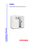
MAN10745 Rev. 4.4 Mar. 2014 Installation Manual MISA SKOPE MISA Cool & Freezer Rooms CONTACT SKOPE SKOPE INDUSTRIES LIMITED A.B.N. 73 374 418 306 PO Box 7543, Baulkham Hills B.C. NSW 2153, Australia Freephone: 1800 121 535 Fax: 1800 121 533 E-mail: [email protected] Website: www.skope.com INSTALLATION & WARRANTY For installation and warranty enquiries please call SKOPE on 1800 121 535 MISA SKOPE MISA Cool & Freezer Rooms Installation Manual MAN10745 Rev. 4.4 Mar. 2014 © 2013 SKOPE Industries Limited. All rights reserved. SKOPE Industries Limited reserve the right to alter specifications without notice. is a registered trademark of SKOPE Industries Limited CONTENTS 1 Specifications . . . . . . . . . . . . . . . . . . . . . . . . . . . . . . . . . . . . . . . . . . . 4 2 Commissioning Installation Guidelines . . . . . . . . . . . . . . . . . . . . . . . . . . . . . . . . . . . . . 6 3 Preparation Positioning the Room . . . . . . . . . . . . . . . . . . . . . . . . . . . . . . . . . . . . . 9 Unpacking . . . . . . . . . . . . . . . . . . . . . . . . . . . . . . . . . . . . . . . . . . . . . 10 Parts . . . . . . . . . . . . . . . . . . . . . . . . . . . . . . . . . . . . . . . . . . . . . . . . . 11 4 Installation Tools and Materials Required . . . . . . . . . . . . . . . . . . . . . . . . . . . . . . 12 Fitting Parts Together . . . . . . . . . . . . . . . . . . . . . . . . . . . . . . . . . . . . 13 Room Installation. . . . . . . . . . . . . . . . . . . . . . . . . . . . . . . . . . . . . . . . 14 Freeblock Refrigeration Unit . . . . . . . . . . . . . . . . . . . . . . . . . . . . . . . 19 Electrics. . . . . . . . . . . . . . . . . . . . . . . . . . . . . . . . . . . . . . . . . . . . . . . 21 Room Inspection . . . . . . . . . . . . . . . . . . . . . . . . . . . . . . . . . . . . . . . . 23 Drop-In Refrigeration Unit . . . . . . . . . . . . . . . . . . . . . . . . . . . . . . . . . 24 5 Servicing Cleaning . . . . . . . . . . . . . . . . . . . . . . . . . . . . . . . . . . . . . . . . . . . . . . 25 Door. . . . . . . . . . . . . . . . . . . . . . . . . . . . . . . . . . . . . . . . . . . . . . . . . . 25 SKOPE MISA Cool & Freezer Rooms Installation Manual iii SKOPE MISA Cool & Freezer Rooms 1 Specifications Compliance SKOPE Industries Limited MISA cool and freezer rooms comply with the Australian and New Zealand building code, the Australian Food Safety Standard 3.2.3 (food premises and equipment) and the Australian Standard AS 4674-2004 (design, construction and fitout of food premises). Modular Construction Rooms Insulation 100mm polyeutherane foam Self-closing, solid foamed swing door Door/s Dimensions Model KLC1AF2M KLC2AF2M KLC3BF2M KLC3CF2M KLC4CF2M KLC4DF2M KLC5DF2M KLC5EF2M KLC6EF2M Internal volume (m³) Freeblock unit 3.07 4.06 6.71 8.37 10.05 11.99 13.95 16.25 18.56 FB 3G FB 3G FB 13G FB 13G FB 16G FB 16G FB 20G FB 20G FB 26G External dimensions (mm) Width Depth Height* 1430 1430 2230 1430 1830 2230 1830 2230 2230 2230 2230 2230 2630 2230 2230 2630 2630 2230 3030 2630 2230 3030 3030 2230 3430 3030 2230 *Internal height 2m, also available in 2.4m. MISA Technical specifications Freeblock Model Temp. range (°C) FB 3G FB 7G FB 13G FB 16G 230 230 230 230 -2 to +2 380-400 (3 phase) 380-400 (3 phase) 230 230 230 230 -18 to -20 380-400 (3 phase) 380-400 (3 phase) FB 20G FB 26G FB 3N FB 5N FB 6N FB 13N FB 20N FB 28N 4 Supply (Volts) 32°C Ambient Nominal Current capacity draw (Watts) (Amps) 1140 2.7 1140 2.7 1520 2.9 2020 4.9 43°C Ambient Nominal Current capacity draw (Watts) (Amps) 950 2.7 950 2.7 1220 2.9 1670 4.9 2470 2.2 2040 2.2 3130 2.5 2530 2.5 770 770 960 1320 2.7 2.7 3.1 4.8 700 700 865 1160 2.7 2.7 3.1 4.8 1830 2.3 1560 2.3 2800 4.1 2375 4.1 Specifications Installation Manual SKOPE MISA Cool & Freezer Rooms MISA Drop-In Technical specifications* Model Temp. range (°C) MB7SF MB13SF MB16SF -5 to +10 MB20SF MB26SF MB4NSF MB9NSF -25 to -5 MB15NSF Supply (Volts) 230 230 230 230 230 230 230 230 Nominal capacity (Watts) 1450 2080 2450 3270 4400 1190 1690 2480 Current draw (Amps) 2.7 2.7 2.9 4.9 2.5 2.7 2.7 4.1 *Refer to the MISA Drop-In specification sheet (PSS0336) for detailed MISA Drop-In specifications. Specifications Installation Manual 5 SKOPE MISA Cool & Freezer Rooms 2 Commissioning Installation Guidelines Registration MISA cool rooms, freezer rooms and drop-in refrigeration units must only be installed by an approved SKOPE registered installer. To register, the installer must complete the SKOPE online registration form, available on the SKOPE website - www.skope.com. SKOPE will confirm if the installer is approved as a SKOPE registered installer for MISA products. Compliance The installer must follow the installation guidelines as set out in this MISA installation manual for the construction of MISA Cool and Freezer rooms. All cool room panels and equipment supplied by SKOPE must be installed in accordance with all relevant laws, regulations, building codes and standards ("Building Codes"). SKOPE may provide information regarding aspects of the Building Codes but this is provided as general information only and does not detract from the installer's responsibility to ensure that all equipment is installed in accordance with the Building Codes The installer must check if the installation is within the tropical zone, which includes everywhere north of Byron Bay, Queensland. If the installation is within the tropical zone, the installer must consider the tropical environment which may require under floor heater wires or other additions. The installer must ensure all electrical and refrigeration work is carried out by licensed technicians. Ventilation The installer must ensure adequate heat extraction and ventilation is in place. If not in place the installer must advise the customer of requirements and advise to have ready and in place for installation. The installer, not SKOPE, is responsible for ventilation of the refrigeration equipment. Installation Installation must be completed in accordance with the MISA installation manual provided by SKOPE. The installer must obtain an accurate MISA room plan from the customer prior to beginning an installation. The installer must carry out a site inspection prior to confirmation of room order to ensure adequate ventilation of the refrigeration unit, and correct dimensions and placement of the room and refrigeration system. Checklist After the room has been installed the installer must complete the MISA installation checklist found on the back page of this manual. A completed copy of the checklist must stay on site and a copy sent to SKOPE. Warranty Subject to the conditions and exclusions set out in the SKOPE Warranty Terms (http://www.skope.com/support/warranty) and provided that the installation is completed by an approved SKOPE registered installer and in accordance with the installation guidelines set out in this MISA installation manual, SKOPE warrants that, for the period of two years commencing on 6 Commissioning Installation Manual SKOPE MISA Cool & Freezer Rooms the date of purchase or 6 months from the date of manufacture (whichever is earlier), the MISA products will be free from any defect in workmanship or material. Where there is any conflict between this installation manual and the SKOPE Warranty Terms, the SKOPE Warranty Terms shall prevail. SKOPE's sole obligation should the products be found upon inspection by or on behalf of SKOPE not to meet the warranty is to, at SKOPE's option, repair or replace the products without charge provided that the liability of SKOPE shall in no event exceed the purchase price of the products. The application of any warranty provided by SKOPE for MISA products is expressly excluded where a defect, malfunction or failure of refrigeration equipment is due to inadequate ventilation, and the customer's recourse will be solely against the installer. Commissioning Installation Manual 7 SKOPE MISA Cool & Freezer Rooms 3 Preparation Safety First Always observe safety precautions when using any electrical appliance. Read these instructions carefully and retain them for future reference. When the appliance is used by or near young children or infirm persons, close supervision is necessary, especially to ensure children do not play with it. Do not use this appliance for other than its intended use. Do not cover the grilles or block the entry or exhaust of airflow by placing objects up against the refrigeration unit. Do not close in or cover the refrigeration unit. Do not probe any opening. Only use this appliance with the voltage specified on the cabinet rating label. Ensure the appliance has adequate ventilation as this is essential to economical, high performance. Be careful not to touch moving parts and hot surfaces. For your own safety and that of others, ensure that all electrical work is done by authorised personnel. Ensure all necessary safety precautions are observed during installation or removal of the refrigeration unit. Do not store explosive substances such as aerosol cans with a flammable propellant in this appliance. Please contact SKOPE Customer Services for advice regarding disposal of this appliance. WARNING Always disconnect the refrigeration unit from the mains power supply before cleaning or maintenance. CAUTION Never overload the power supply, which could damage the appliance and product. See the rating label for the safe power supply and current draw. CAUTION There must be adequate ventilation and air flow around the Freeblock refrigeration unit. The ambient temperature around the condenser must not exceed 43°C. A poorly ventilated Freeblock refrigeration unit may overheat. Mechanical extraction of condenser air into ceiling space or preferably out of the building is advised. See page 19 for Freeblock refrigeration unit safety and service guidelines. 8 Preparation Installation Manual SKOPE MISA Cool & Freezer Rooms Positioning the Room Room Location Before assembling the room, decide where to position it. The room is installed from the inside so can be positioned in-place in tight spaces. Once installed, the room should not be moved. We recommend that the room is installed in the coolest place possible. Do not install the refrigeration unit in direct sunlight. The ambient temperature around the Freeblock refrigeration unit must not exceed 43°C. Check manufacturers specifications if installing a third party refrigeration unit. The room should be installed either away from walls to enable access for cleaning, or sealed to the walls to prevent harbourage of vermin. Enclosed areas above the room must be pest proffed. Allow adequate space for the door to open and close properly. Self-closing swing doors are aligned and tensioned at the factory and must be unobstructed. Refrigeration units must be supported well to allow for easy cleaning. Ensure adequate extraction or ventilation is available. Prevent any noise nuisance to nearby residences and businesses. Refrigeration units should be placed away from neighbouring bedroom windows, office windows, multiple walls and corners. Ensure the room sits on a level surface. There must be no more than 5mm difference between each end of the floor. Level flooring prevents panel misalignment and ensures that the door shuts and correctly seals. IMPORTANT Ensure the room is installed on a level surface. If the room is being installed without a MISA floor, additional site preparation (such as floor surface preparation) should be completed prior to room installation. Freezer rooms without a MISA floor should be installed onto insulated concrete. External cold and freezer rooms are not permitted unless an approved enclosed access is provided Ventilation & There must be adequate ventilation and air flow around the Freeblock Condenser Air refrigeration unit. Poor ventilation will void the warranty. The ambient Extraction temperature around the condenser must not exceed 43°C. A poorly ventilated Freeblock refrigeration unit may overheat. Mechanical extraction of condenser air into ceiling space or preferably out of the building is advised. Power Supply This appliance must be installed in accordance with the relevant electrical wiring rules and regulations (AS/NZS 3000). A suitable isolation switch (acting in all supplies) must be incorporated in the fixed supply wiring. Refer to the rating label for power supply requirements. The rating label is located on the Freeblock refrigeration unit. We recommend that single-phase Freeblock refrigeration units are hard wired to a 20 Amp circuit with isolation switch, and that 3-phase Freeblock units are connected to a suitable circuit as required as specified on the unit rating label. Preparation Installation Manual 9 SKOPE MISA Cool & Freezer Rooms Unpacking The room is supplied in two packs. The first pack contains all the parts required to build the room, and the second pack contains the SKOPE supplied refrigeration unit (where applicable) (Freeblock refrigeration unit pictured). It is not necessary to unpack the refrigeration unit until the room has been built. To unpack the room 1. Open the first pack containing the room parts. Keep the strapping and wooden cross piece as they are required to assist with removal of the refrigeration unit. 2. Lift the door from the top of the pack. Ensure the door is kept upright to avoid potential misalignment. 3. Remove the box from the pack. The box includes small parts. 4. Remove the plastic film from the edge pieces. 5. Lay the remaining parts out on the ground. Start with the edge pieces, then the wall panels, and then the ceiling and floor panels. To unpack the refrigeration unit 1. Remove the cover from the crate. 2. Retrieve the strapping from the first pack, and thread it through the hook on top of the refrigeration unit. Tie into a secure knot to form a loop. 3. Insert the wooden cross piece into the loop and lift the Freeblock refrigeration unit from the pack. 10 Preparation Installation Manual SKOPE MISA Cool & Freezer Rooms Parts Standard The following parts are required for a standard room installation. Additional Room Parts parts may be required. 6 5 11 11 7 4 2 10 9 3 8 1 Parts list No. 1 2 3 4 5 Item Floor panel Fast fit insert Edge piece 2-Way corner cap Wall/Ceiling panel 6 Ceiling hanger 7 Door panel 8 Cam lock cover 9 Internal ramp kit 10 Refrigeration unit 11 Bell and light kit Corner insert Description Grey/silver colour. Tread side up. Used to align panels quickly and correctly. Used to create right angle corners. Used to join edge pieces. Standard panels are white. Available in different sizes. Used to hang ceiling on top edge pieces (on top of walls). Wall panel with door. Plastic cap to cover cam lock holes. White for walls and ceiling, and silver for floor. Internal ramp used at base of door. Refrigeration unit. Bell alarm and internal light indicator. Not pictured. Plastic cover for interior corners. Additional The following parts may be required in place of or in addition to the parts Parts listed above. Additional parts list No. Item Description Fitted behind door to minimise cool air loss during door 12 Air curtain opening. - U Channel Not pictured. For use with concrete floor room. - U Channel corner kit Not pictured. For use with concrete floor room. - Edge piece joiner kit Not pictured. Used to join edge pieces from end to end. - 3-Way corner kit Not pictured. For use with multiple cell rooms. - Door switch Not pictured. For use with freezer rooms. Preparation Installation Manual 11 SKOPE MISA Cool & Freezer Rooms 4 Installation Tools and Materials Required The following tools and materials are required for a standard room installation. Additional tools and materials may be required. Tools list Item Cam lock tool Silicone Mastic Knife Gloves Description Used to lock panels and panel edges together. Used to seal panels and panel edges. Recommended for wall panels in hot humid areas. Unpacking To be worn during installation Cam Lock Two cam lock tools are supplied. One is for use with the room to lock panels Tools and panel edges together (supplied with room), and the other is used to lock the MISA Freeblock refrigeration unit into place (supplied with MISA Freeblock refrigeration unit). Do not apply more than 1.5kg of pressure on the tools when locking the cams. Excessive pressure will damage cam locks. IMPORTANT Do not apply more than 1.5kg of pressure on the cam lock tool when locking the cams. The room cam lock tool is suitable for use with 60mm panels and requires modification for use with 100mm panels. To modify the cam lock tool for use on both 60mm and 100mm panels, remove the sleeve from the pointed end of the tool. Sleeve Pointed end Room cam lock tool The cam lock tool can also be used to assist with moving panels. Insert the tool into the cam holes and use the tool as a handle to lift and manoeuvre panels (see image below). Cam lock tool Cam hole Door panel Silicone and Silicone should be used to ensure secure attachment and to keep moisture Mastic and grime from out of small gaps and spaces. Mastic should be used in areas with high heat and humidity. 12 Installation Installation Manual SKOPE MISA Cool & Freezer Rooms Fitting Parts Together Panels and edge pieces are fitted together using fast-fit inserts, panel cam locks and sealant in-between panels and end pieces. Fast-Fit Inserts Fast-fit inserts are plastic plates which slot into the edges of panels and edge pieces. One fast-fit insert should be used on every second cam lock. Fast-fit insert Fast-fit insert in place Fast-fit inserts ensure correct alignment and assist with locking the panels together. As a general rule, a fast-fit insert should be used on every second slot where practical. Panel Cam Cam locks are built into floor, wall and ceiling panels. They cannot be Locks removed or replaced. The cams move through three stages when locking - open, closed and locked. A hook extends out from the cam when rotated, fits into the slot on the aligned room piece and pulls in to seal the two pieces together. Do not apply more than 1.5kg of pressure on the tool when locking the cams. Excessive pressure will damage the panels. To lock the cams 1. Align two room parts and insert the pointed tip into the cam hole on one of the parts Floor panel (room part) Cam lock tool Cam hole Edge piece (room part) 2. Rotate the tool clockwise to lock the room parts together. Installation Installation Manual 13 SKOPE MISA Cool & Freezer Rooms Room Installation The steps below detail installation of a standard four sided cool room. Before installing, ensure the site has been properly prepared. The room should be built in place, not moved into place after installation. Ensure the room sits on a level surface. There must be no more than 5mm difference between each end of the floor. Level flooring prevents panel misalignment and ensures that the door shuts and correctly seals. IMPORTANT Ensure the room is installed on a level surface. Standard MISA The steps below apply to rooms with a standard MISA floor. If installing a Floor floor-less or set-down room, refer to the steps on the next page. To install a standard MISA floor 1. Lay the floor panels into position according to the plan. The textured tread side of the panels should face up. 2. Apply a bead of silicone between the floor panels. 3. Align the floor panels with fast-fit inserts. 4. Lock the floor panels together with cam locks. 5. Check the floor is level and in the correct position. 6. Apply a bead of silicone approximately 20mm out from the floor perimeter (on the ground surface). 7. Use fast-fit inserts to align the floor panel edge pieces around the floor panel perimeter (see page 13). 8. Lock floor panel edge pieces to the floor panels with cam locks (page 13). Continued over page 14 Installation Installation Manual SKOPE MISA Cool & Freezer Rooms 9. Silicone and slot a 2-way corner cap into each corner of the floor. The corner cap edges slide under the floor edge pieces for a tight fit. Floorless The room can be installed directly onto a concrete surface without using Room MISA panel flooring. U-Channels are used to support the wall panels. The Installation U-Channel frame must be bolted in place and sealed with silicone prior to fitting the wall panels. Freezer rooms without a MISA floor must be installed onto insulated concrete. U-Channel rooms must always be installed by a qualified technician. IMPORTANT Freezer rooms without a MISA floor must be installed onto insulated concrete. Follow the steps below to install the U-Channel floor frame. To install the U-Channel frame 1. Mark out the room on floor according to plan with a chalk string line. Ensure the line is square and correct. 2. Lay out the U-Channel corners as pictured. 3. Lay the U-Channel lengths on the chalk line. The lengths will need to be cut on one end to fit. 4. Check to make sure all sides are square. The easiest way to do this is to measure the diagonals from corner to corner, the measurements must be mm perfect. 5. Silicone and fix the back and sides (not the door front) of the U-Channel frame to the ground with concrete plugs. 6. Cut the front U-Channel frame piece into two pieces to allow for the door opening. To calculate the door opening size, measure the overall size of the door frame and add 24mm (12mm each side for door trim). For example, if the door is 800mm wide the cut-out opening size should be 824mm. Continued over page Installation Installation Manual 15 SKOPE MISA Cool & Freezer Rooms 7. Make a 30mm x 30mm square cut to each side of the front of the U-Channel (door side) to allow the door bottom gasket seal to close on the face of the curved U-Channel. 8. Silicone and fix the two front pieces of the U-Channel frame to the ground with concrete plugs. 9. The room can now be assembled. Use mastic inside the U-Channel and slot the wall panels into the U-Channel. Walls and Use the supplied plan to piece together different sized wall and ceiling Ceiling panels. Due to variance of room configuration and/or the place of installation, it may be necessary to reorder these steps. For example, the ceiling may need to be moved into position prior to fitting all walls due to limited space above the room, or the door maybe fitted on a side wall rather than a front wall. To install the walls and ceiling 1. Starting at the back wall, fit a corner wall panel and lock into place. 2. Fit a wall panel edge piece. Use fast-fit inserts to align and lock in place with wall panel cam locks. Ensure the top edge of the edge piece is level with the top of the wall panel. 3. Fit a second corner wall panel to create a right angle. Use fast-fit inserts to align and lock in place with wall panel cam locks. Continued over page 16 Installation Installation Manual SKOPE MISA Cool & Freezer Rooms 4. Continue fitting back and side wall panels, working from the back towards the front of the room. Use fastfit inserts to align wall panels correctly and lock in place with cam locks. Note: Rooms fitted with MISA Freeblock refrigeration unit will include a shorter panel. The refrigeration unit is installed above this panel. 5. Fit the top edge pieces on top of the back and side walls. 6. Slot the ceiling support brackets into the edges of the ceiling panel/s. 7. Lift the ceiling panel/s onto the room walls, hang using the ceiling supports and lock into place. If fitting multiple ceiling panels, fit the rear panel first and work forward. 8. Fit the front of the room. If the door panel makes up a corner, start with this. If the door panel has wall panels on either side, start from one side and work across. Do not fit the door panel last. Continued over page Installation Installation Manual 17 SKOPE MISA Cool & Freezer Rooms 9. Fit the top edge piece/s on top of the front wall. 10. Slot a 2-way corner cap into each corner of the ceiling. 11. Fit a corner insert into each corner inside the room. 12. Fit the ramp inside the room at the bottom of the door frame. Drill holes as necessary and fix in place with supplied fixing screws. 13. If supplied, fit the air curtain to the top of the door frame. Light & Bell A light and bell alarm kit is supplied with the room and must be fitted. Alarm Kit Australian standards require the light and light switch to be fitted inside the room, and the indicator light fitted outside the room. The indicator light illuminates when the interior light is on. The door safety bell should be fitted to the door (fitting instructions are included with the bell). The light should be mounted inside the room under the evaporator or on the ceiling. The light switch should be mounted inside the room next to the door. The light indicator should be mounted beside the door on the outside of the room. A licenced electrician must be used to wire up the light, light switch and light indicator, see page 21 for more information. 18 Installation Installation Manual SKOPE MISA Cool & Freezer Rooms Freeblock Refrigeration Unit Introduction The SKOPE MISA Freeblock side mount is a wall mounted refrigeration unit which is easily positioned and locked onto the side of the room using the supplied cam lock tool. The standard opening size for the refrigeration unit is 800mm wide x 400mm high. The following information applies to SKOPE MISA Freeblock side mount refrigeration units. For information on SKOPE MISA Drop-In refrigeration unit installation refer to “Drop-In Refrigeration Unit” on page 24. If the room is supplied with a third party drop-in unit or remote refrigeration system, ceiling or wall panels will need to be cut to fit the refrigeration unit. If it is necessary to cut into the panels, ensure measurements are correct before cutting and take care when cutting as the panels are delicate. Do not cut through cam locks. Ensure that the ceiling panels have adequate support for the refrigeration unit. If more ceiling support is required, hangers on wires attached to the cool room roof can be used. The wires can be attached to either the building internal roof beam/s. Or alternatively a strengthening beam or plate can be installed across the top of the room to support the refrigeration unit. Refer to the documentation provided with the drop-in or remote refrigeration unit for further information. IMPORTANT The refrigeration unit is heavy and requires two or more people to lift. Safety and When installing, using, maintaining and servicing the Freeblock refrigeration Service unit, follow the safety and service guidelines below: Guidelines Installation must be carried out in strict compliance with the diagrams and instructions supplied by the manufacturer. Installation Installation Manual Electrical connections must meet all relevant safety standards. Use safety gloves to protect your hands from cuts. The unit is not suitable for use in explosive environments, therefore the use of the unit in an explosion dangerous atmosphere is absolutely forbidden. The unit is not suitable for use in corrosive environments. In such cases protect the condenser coil and evaporator coil with appropriate means. Servicing must be completed by trained personnel or manufacturer according to the provisions supplied by EN378. When maintenance or servicing involves operations on the refrigeration circuit, empty the system and allow it to reach atmospheric pressure. Do not discharge the refrigerant gas into the atmosphere. Refrigerant gas must always be recovered by specialised technicians using suitable equipment. Quantity and quality of the refrigerant charge are indicated on the data plate. Do not use alternative refrigerants (especially inflammable fluids e.g. hydrocarbons) or air. Do not modify or alter the refrigerating circuit or its components. The unit shall only be used following the instructions indicated by the supplier. Any incorrect use can result in damage to the unit and represents a serious danger for peoples health. 19 SKOPE MISA Cool & Freezer Rooms The user shall protect the system from external fire hazards. The user is strongly recommended to contact the manufacturer before attempting any intervention on the unit and any use not corresponding to the manufacturers directions (in particular the field of application). Please enquire about the possible dangers connected with improper use of the unit. Note: Damages due to improper connections void any warranties. Drainage Although the unit has its own condensation tray, high heat and humidity may cause the tray to overflow. To compensate for this the Freeblock refrigeration unit must be installed with a drain connection to a waste outlet. Ventilation & There must be adequate ventilation and/or extraction for air flow around the Condenser Air Freeblock refrigeration unit. Poor ventilation will void the warranty. The Extraction ambient temperature around the condenser must not exceed 43°C. A poorly ventilated Freeblock refrigeration unit may overheat. Mechanical extraction of condenser air into ceiling space or preferably out of the building is advised. Power Supply We recommend that single-phase Freeblock refrigeration units are hard wired to a 20 Amp circuit with isolation switch, and that 3-phase Freeblock units are connected to a suitable circuit as required as specified on the unit rating label. Refer to “Electrics” on page 21 for more information. Refer to the rating label for power supply requirements. The rating label is located either on the cabinet interior or on the Freeblock refrigeration unit. Installation Follow the steps below to install the Freeblock refrigeration unit. To install the refrigeration unit 1. Carefully lift the refrigeration unit up and insert the evaporator into the wall space. Access can be made easier by lifting the ceiling corner above the refrigeration unit space. 2. Ensure the refrigeration unit is fully inserted and flush with the interior wall surface. 3. Use the large cam lock tool to lock the refrigeration unit into position. Remove the front panel from the refrigeration unit to access the top cam locks. The bottom cam locks are accessed from inside the room. 4. Refit the front cover. 5. Connect up the electrical components (see page 21), complete the room inspection (see page 23) and installation checklist (see back page). 20 Installation Installation Manual SKOPE MISA Cool & Freezer Rooms Electrics All electrical wiring should be completed by a licenced electrician and installed in accordance with the relevant electrical wiring rules and regulations (AS/NZS 3000). Refrigeration Once the room has been assembled and the unit fitted, the refrigeration unit Unit Wiring electrical wiring can be connected. Two electrical cables exit the top of the refrigeration unit. One of these is the mains supply cable, and the other is the door switch cable. The mains supply cable is made up of active, neutral and earth wires. We recommend that single-phase Freeblock refrigeration units are hard wired to a 20 Amp circuit with isolation switch, and that 3-phase Freeblock units are connected to a suitable circuit as required as specified on the unit rating label. The door switch cable is wired up to a door switch located above the door. The door switch must be fitted to freezer rooms and is optional on cool rooms. If not being used the door switch should be left open circuit. Interior Light A light kit is supplied with the room and must be fitted. Australian standards require the light and light switch to be fitted inside the room, and the indicator light fitted outside the room. The indicator light illuminates when the interior light is on. The light should be mounted inside the room under the evaporator or on the ceiling. The light switch should be mounted inside the room next to the door. The light indicator should be mounted beside the door on the outside of the room. A licenced electrician must be used to wire up the light, light switch and light indicator (see diagram below). Legend 1 No. 1 2 3 4 5 P N 2 3 Description Refrigeration unit Room Interior light Indicator light Light switch 4 5 Installation Installation Manual 21 SKOPE MISA Cool & Freezer Rooms Door Heater The door heater wires are located behind inside the door panel around the Wiring door opening. The door heater electrical box is fixed to the door panel and can be removed by undoing the fixing screws. Refer to the wiring diagram below for door heater wiring details. Legend No. 1&8 3&4 5&6 2&7 Description Power supply Heater valve Remote contact Door heater 8 7 6 5 4 3 2 1 Electronic The MISA Freeblock refrigeration unit is fitted with electronic controller. Controller Refer to the electronic controller documentation supplied with the refrigeration unit for further information. 22 Installation Installation Manual SKOPE MISA Cool & Freezer Rooms Room Inspection Once the room has been assembled and the refrigeration unit fitted, inspect that the room is assembled correctly by shutting yourself inside the room. If no light filters through, the room is assembled correctly. If light does filter through, realign the panels to seal any gaps, and check that the door is correctly fitted (see page 25). After checking that the room is assembled correctly, fit the plastic caps over the cam lock holes. The white caps are for the walls and the silver caps are for the floor. Installation Installation Manual 23 SKOPE MISA Cool & Freezer Rooms Drop-In Refrigeration Unit The following information applies to SKOPE MISA Drop-In refrigeration units. For information on SKOPE MISA Freeblock refrigeration unit installation refer to “Freeblock Refrigeration Unit” on page 19. If the room is supplied with a third party drop-in unit or remote refrigeration system, refer to the documentation provided with the drop-in or remote refrigeration unit for further information. Safety When installing, using, maintaining or servicing the Drop-In refrigeration unit, follow the safety and service guidelines on page 18. Installation The SKOPE MISA Drop-In refrigeration unit is designed to be located on top of the cool/freezer room. Follow the instructions supplied with the Drop-In refrigeration unit. Once installed, have the Drop-In refrigeration unit commissioned by a licenced technician before initial start-up. Drainage Although the unit has its own condensation tray, high heat and humidity may cause the tray to overflow. To compensate for this the Drop-In refrigeration unit must be installed with a drain connection to a waste outlet. Ventilation There must be adequate ventilation and airflow around the Drop-In refrigeration unit. Poor ventilation will void the warranty. The unit condensing temperature must not exceed 45°C. If adequate airflow is not available, mechanical air extraction must be used. Mechanical extraction of condenser air into ceiling space or preferably out of the building is advised. Enclosures If the Drop-In refrigeration unit is enclosed, the enclosure must have an air intake grille and the ceiling above must have adequate extraction to the outside of the building. This must be in place prior to room installation and should be done based on the installer recommendations. This work is not the responsibility of SKOPE or the SKOPE approved installer. Power Supply We recommend that single-phase Freeblock refrigeration units are hard wired to a 20 Amp circuit with isolation switch, and that 3-phase Freeblock units are connected to a suitable circuit as required as specified on the unit rating label. Refer to “Electrics” on page 21 for more information. Refer to the rating label for power supply requirements. The rating label is located either on the cabinet interior or on the Freeblock refrigeration unit. Controller The electronic controller control panel should be located beside the room door. 24 Installation Installation Manual SKOPE MISA Cool & Freezer Rooms 5 Servicing Cleaning Room Periodically wipe the inside and outside of the room with a damp cloth. Use neutral or slightly alkaline detergent, and rinse and dry the panels after cleaning. Isolate the refrigeration unit from the power supply when cleaning around electrical components. Condenser To ensure trouble-free performance, the condenser coil must be kept clean. Coil We strongly urge monthly cleaning with a soft brush to remove dust and fluff, and a thorough cleaning every six months. The condenser coil must be kept clean for efficient and reliable operation. Always isolate the refrigeration unit from the power supply when cleaning the condenser coil. Door Door Seal To ensure the room operates correctly and efficiently, the door must close and seal correctly. To check this, enter the room and shut the door. No light should filter around the door opening. If light is filtering through, check the door and gasket for alignment and adjust as necessary (see Door Alignment and Door lock & Gasket Alignment below). Door If a door is out of alignment, follow the steps below to realign it. Alignment To realign the door 1. Open the door and remove the top door hinge cover. 2. Close the door and loosen the two adjustment screws. 3. Move the top of the door left or right as necessary to align correctly. 4. Once the door is correctly aligned, tighten the two adjustment screws and refit the door hinge cover. Servicing Installation Manual 25 SKOPE MISA Cool & Freezer Rooms Door Lock & The door lock can be adjusted to ensure the door closes and gasket seals Gasket on the door opening. If the gasket is not sealing correctly, follow the steps Alignment below to adjust the door lock as necessary. To realign the gasket 1. Open the door and use a small screwdriver to unclip and remove the door handle cover from the inside of the door. 2. Loosen the two adjustment screws. 3. Move the lock section of the handle in or out as necessary to align correctly. 4. Once the door is correctly aligned, tighten the two adjustment screws and refit the door lock cover. Door Heater The door heater wire runs around the perimeter of the door opening. Refer Wire to page 22 for wiring information. Follow the steps below to access the door heater wire. To access the door heater wire 1. Ensure the refrigeration unit is isolated from the power supply. 2. Open the door. 3. Remove the door heater electrical box to access the heater wire terminals. 4. Pry the edge of the door opening off to access the heater wire. 26 Servicing Installation Manual MISA Installation and Commissioning Checklist The following checklist must be completed by the installer after the room has been installed. A completed copy must stay on site and a copy sent to SKOPE for warranty registration - [email protected]. Site Details Approved installer: Customer’s name: Address of installation: Date of installation: Description of work: Compliance The installation has been completed in accordance with: the MISA installation manual the customer’s plans and specifications the terms of local authority consents all relevant laws, regulations, building codes and standards Construction Tick to indicate the following key installation details have been adhered to: There is adequate ventilation and airflow around the refrigeration unit. If adequate airflow is not available, a suitable heat extractor has been installed. The room has been installed on a flat and level concrete surface as per the installation manual. Room inspection has been performed. The supplied roof supports have been used to support the room roof. Operation Tick to indicate everything is operating correctly: Airflow is unimpeded on the inside and outside of the room. The refrigeration unit is operating correctly. The door is sealing correctly (adjust door if necessary). Heater element/s are operating correctly (freezer rooms only). Please record the following information and tick the boxes once installation has been completed and the room powered up for the first time. Note: Any issues or irregularities must be investigated and rectified to specifications. Ambient air on (air onto condenser) must not exceed 43°C. The ambient air on temperature at condenser - when first powered up: after 15 minutes: after 30 minutes: after 60 minutes: Unit current draw (Amps): Power supply: 240V single phase 415V three phase