1
5000 Series 8 Zone Panel Installation Manual
NESS 5000, 8 ZONE INSTALLATION MANUAL
NESS SECURITY PRODUCTS
SYDNEY
BRISBANE
MELBOURNE
PERTH
Phone: (02) 8825-9222 (Head office)
Phone: (07) 3343-7744
Phone: (03) 9878-1022
Phone: (08) 9328-2511
Copyright * by NESS SECURITY PRODUCTS December 1988
To the best of our knowledge, the information contained in this manual is correct at the time of going to print.
NESS Security Products reserve the right to make changes to the features and specifications at any time and
without notice in the course of product development.
CONTENTS:
INTRODUCTION
Terminology
Features
5000 SERIES Optional Equipment
INSTALLATION
Unpacking
Installation Procedure
Inputs
Outputs
Power
Earthing
Power Up Check
Wiring Diagram
CONTROLS AND INDICATIONS
Keypad
Audible Indications
Visual Indications
Zone Indications
INSTALLATION AND PROGRAMMING
Access to the Installation Program Mode
How to Program
ZONE OPTIONS
Setting Zones to Instant
Setting Zones to Delay
Setting zones to Handover
Setting Zones to Secondary Entry Delay
Setting Zones to 24 Hour Audible
Setting Zones to 24 Hour Silent
Zone Sensitivities
Setting Zones to One Trigger
Setting Zones to Two Trigger
Setting Zones to Vibration Sensitivities
Test Procedure
MISCELLANEOUS OPTIONS
Lockout and Conditional Lockout
keyswitch Operation
Keypad Arming
Auto Exclusion of Zones
Entry Warning Beeps
Panic Alarms
Zone, Tamper and Code Alarms
Monitor Alarms to Dialler
Siren Reset Time
Checks Before Entering Client Mode
TESTING
Testing
Troubleshooting
Specifications
Programming Sheet
2
2
4
5
6
6
6
6
7
7
8
8
8
8
8
8
9
9
10
10
10
10
11
11
11
11
12
12
12
13
13
13
14
14
14
15
15
15
16
16
16
17
17
17
18
18
19
20
21
Page 1
5000 Series Dialler
INTRODUCTION
Thank you for purchasing the NESS 5000
SERIES 8 zone Control Panel. The system was
designed to provide you, the installer, with
features and versatility never before offered
in a Control Panel.
The high-impact polycarbonate housing not
only offers strength but is aesthetically pleasing
and therefore easily marketable Both the main
circuit board and the lid are removable which
allows you to easily install the system. Plug in
terminal blocks eliminate the need to unscrew
all connections before removing the board to
provide ease of installation and service.
NESS Security Products over the years have
always provided technically innovative quality
products which have led to the 5000 SERIES
being one of the most reliable on the market
today. NESS' unparalleled technical support
and service reinforces our commitment to the
industry.
This manual will tell you all you need to know
about installing and programming the system
options. For client programmable features and
operating instructions, refer to the
INSTRUCTION MANUAL
TERMINOLOGY *************************************************************************************************
In order to fully understand the 5000 SERIES 8
Zone Panel, you should become familiar with
the terminology used throughout this manual.
The following is a brief system description.
MODES OF OPERATION
The Panel may be operated in 3 modes.
(1)Installation Program Mode; enables
system parameters such as Zone types
(Delay, Instant, Handover etc), to be
programmed or reprogrammed by the
installer.
GENERAL
The 8 Zone Panel is constructed of
Polycarbonate which is a material used in
many high security applications such as bullet
proof glass'. The panel is designed to meet or
exceed Australian Standard AS.2201
Many features are provided to ensure :
(2)Client Program Mode; allows a client with
a Master Code the capability of
programming User Codes, Monitor Zones,
Entry and Exit times etc.
Ease of installation and service; eg.
removable lid, clip in PC boards and
plug-in terminal blocks
(3)Normal Operating Mode; allows day to day
operation by one or more clients.
POWER
Flexibility; eg. full Programmability via
the inbuilt Keypad.
A.C. power is supplied from the mains to the
panel via a Plug-pack transformer which also
provides an Earth connection to improve the
Lightning Protection. A Stand by Battery is
fitted to ensure that the system continues to
operate it mains power is interrupted. The A.C.
power is checked continuously while the battery
is checked every hour and whenever the
system is Armed. Battery testing is performed
under load for extra security. This is called a
Dynamic Battery Test.
System Integrity; eg. Dynamic Battery
Test.
High Security; eg. inbuilt Vibration
Tamper.
Page 2
5000 Series Dialler
INPUTS
Perimeter may be protected whilst the internal
zones are ignored.
A total of ten End-of-line Monitored Inputs
are provided for connection to various devices.
Before Arming, all zones should be Secured.
Activation of a detection device will cause the
appropriate zone to become unsecured and
may cause an alarm.
One or more Defection Devices may be
connected to any of the eight End-of-Line
monitored zone inputs. The inputs can be
programmed to suit various applications. A
Movement Detector may require Two Trigger
operation, whereas a Reed Switch will require
Normal One Trigger operation. A Vibration
Sensor would be programmed to one of eight
Vibration Sensitivities. Smoke Detectors and
Holdup Switches are required to operate
always and would therefore be programmed to
24 Hour operation.
After Arming, the Panel will ignore most
detection devices for the duration of the Exit
Time to allow departure from the premises.
During that time, certain Audible Warnings may
be sounded by the beeper eg. a Low Battery,
Mains Fail or a Zone Unsecured warning.
At the end of Exit Time, any zone that is still
Unsecured may be Automatically Excluded.
If a detector becomes faulty, the client may
Manually Exclude the associated zone so that
it is ignored and cannot generate an alarm.
Manually Including the zone will allow it to
generate an alarm again.
The Control Panel housing, external siren
covers and many types of detectors are
protected by Tamper switches designed to
detect attempts to disable those devices. The
tamper switches are connected to the Tamper
Input. Activation of any tamper switch or its
wiring will cause an immediate alarm at any
time in all modes except Installation Program
Mode. The system may be controlled by a
Remote Keyswitch connected to the
Panic/Keyswitch Input. Panic Buttons may
also be connected to the same input.
After the expiry of the Exit Time, the system will
become fully Armed. An Instant Zone
becoming unsecured will cause an immediate
alarm. The alarm may be Silent it the system is
monitored by a Central Station via a 5000
SERIES Dialler or a NESS Securitel'
Interface Unit or it can be Audible in which
case the Sirens sound for the programmed
Reset Time while the Strobe Lights will
continue running until the Panel is Disarmed.
OUTPUTS
Separately fused Siren outputs allow the
connection of Internal and External Horn
Speakers. A Latched output is provided for
Strobe lights and a Resetting output for
miscellaneous alarm devices such as Piezo
sirens.
When the alarm Resets, any zone that is still
unsecured will be automatically Locked Out to
prevent that zone from causing further alarms.
If the zone is programmed for Conditional
Lockout, the zone will become active again
when the zone is secured so that it may cause
further alarms whenever the zone becomes
unsecured again.
Other outputs are provided for connection to
optional 5000 SERIES equipment. Remote
Keyswitches, Standard Keypads and
Intelligent Keypads can be located at remote
points such as front or back doors to control
the system and provide additional convenience
and security. Satellite Sirens ensure maximum
security against attacks to the Control Panel,
Sirens or interconnecting cables. It contains it's
own battery and electronics to operate
independently of the Control Panel.
All alarms are stored in Memory so that they
can be recalled after the Panel is Disarmed.
The zone that caused the alarm is stored as a
Primary Alarm and any zones that are
Unsecured within the Reset Time are
Secondary Alarms.
When the client enters the premises, the Panel
will ignore those zones that are programmed for
Delay, Secondary Delay or Handover for the
duration of the relevant Entry Time. Failure to
Disarm the Panel within this time will cause an
alarm.
OPERATION
In Normal Operating Mode, the Panel may be
Armed ready to detect intruders. It may be
Disarmed when the premises are occupied or
switched to Monitor Mode to allow only
selected zones to be Armed simply. Thus the
Page 3
5000 Series Dialler
FEATURES
Zone inputs can be split with two
end-of line resistors so that two pieces
of equipment (eg. reed switches) can
both be monitored to provide maximum
security.
Ultra-modern and impact resistant
housing.
8 fully programmable zones plus tamper
and panic inputs.
Fully programmable via Control Panel
Keypad - eliminates the need for
expensive programmers or PROMs.
ALL inputs and outputs are heavily
protected against lightning and high
voltage power supply transients. An
earth terminal is provided for extra
protection.
All Programming data is permanently
stored in a non-volatile EEPROM - more
secure than battery backed-up memory.
Fail-safe input system detects any
component failure in the zone input
circuitry and generates an alarm.
Separate Installation and Client
Programming modes.
Detectors can be programmed to alarm
on 1 or 2 triggers - cheaper and more
secure than using pulse count
detectors.
The Control Panel housing has 4
separate tamper systems - Keypad,
Wall, Lid and Panel impact.
Tampers are monitored 24 hours a day.
Vibration sensors can be connected to
any or all zones without additional
hardware and can be programmed to
alarm on 1 of 8 sensitivities.
Additional security is provided by the
various programming options:
•
Arm via a code
•
Exclude zones via a code
•
Partial Arming (Monitor mode)
•
Extra Delay zone to cater for long
and short entry paths
•
Handover zones
Separate Monitor alarm, 24 Hour alarm
and Auxiliary outputs.
Easy connection of the 5000 SERIES
satellite siren to greatly increase the
security of your system.
Special inputs to allow the connection
of NESS Remote Keypads. These
keypads offer full programmability and
operation of the Panel from a remote
location.
TRUE DYNAMIC BATTERY TEST
every hour and upon Arming thus
guaranteeing the system's integrity.
Indication of unsecured zones while
Arming.
Comes complete with an a.c. plug-pack
and a 6.5 AH battery to maintain system
security under all power supply
conditions.
Outputs are separately fused.
Page 4
5000 Series Dialler
5000 SERIES OPTIONAL EQUIPMENT
The following optional 5000 SERIES equipment is available for use with the 8 Zone Control Panel.
REMOTE KEYPAD
SECURITEL INTERFACE UNIT
This Keypad is connected via 4 wires and can
increase convenience of operation and security'
of the system. It allows full programmability and
operation with Audible feedback only.
This is a plug-in programmable device which
offers similar features to the Auto-Dialler but
provides a higher level of security in that the
telephone line is monitored at all times.
INTELLIGENT REMOTE KEYPAD
RADIO CONTROL EOUIPMENT
This Keypad is connected via 4 wires and
allows full programmability and operation of the
system with complete Visual and Audible
feedback.
A 4-channel Radio Control Receiver can be
connected to the Panel to receive signals from
the NESS hand-held Emergency/Panic buttons.
PRINTER/REAL TIME EVENT RECORDER
SATELLITE SIREN
Records and or prints all activities of the
Control Panel with a Time and Date Stamp.
This Siren allows you to offer higher security for
the installation It the system is attacked.
Connected via 4 wires, It is fitted with It's own
battery and electronics and operates
independently of the Control Panel.
OUTPUT EXPANDER
A plug-in device used for interfacing to Direct
Line or other equipment. Requiring no
programming, It provides 20 outputs such as
individual alarms, zone Excluded etc.
TELEPHONE AUTO DIALLER
This is a plug-in device and is fully
programmable from the Control Panel's
keypad. It is capable of automatically
communicating information to most common
digital receivers and/or to the client's home
over a normal telephone line.
ZONE EXPANDER
A plug-in device that provides an extra 16
zones and is fully programmable from the
Control Panel's keypad.
DIALLER REMOTE CONTROL
This is a small hand-held device which allows
remote communication with the Auto-Dialler via
the telephone line. It can be used to Arm the
Control Panel, operate an output or receive
status reports.
Page 5
5000 Series Dialler
INSTALLATION
Included in the 8 Zone Control Panel packaging
is the following equipment.
1 x 5000 SERIES 8 Zone Control Panel
1 x 12 Volt 6.5 A-h Rechargeable Battery
1 x 17 Volt Plug pack
3 x Ten Way Terminal Blocks
12 x 2K2 Resistors
1 x Spare Fuse 1.5 Amp
1 x A1len Key
1 x Installation Manual
1 x Instruction Manual
INSTALLATION PROCEDURE ************************************************************************************
For ease of installation it is recommended that the following procedure be followed:
1) Remove the cardboard terminal designation card.
2) CAREFULLY remove the keypad ribbon from the circuit board and unclip the lid .
3) Remove the rear tamper and battery terminal blocks from the circuit board. Unclip and remove the
circuit board by pushing the retainer clips up. (located just below the battery)
4) Remove the battery.
5) Mount the polycarbonate rear housing. Wire the terminal blocks as per wiring instructions shown
on the terminal designation card and as explained in this section.
6) Replace Battery. Clip in circuit board. Plug in the terminal blocks except those for the Satellite and
Battery.
7) Replace lid and plug in keypad ribbon cable to the connector.
8) Replace the Terminal Designation Card.
9)Perform the Power up check.
10) Program Installation Options.
11) Carry out Test Procedure.
12) Perform “Check Before Entering Client Program Mode”.
INPUTS *********************************************************************************************************
The Control Panel contains 10 separate monitored inputs.
8 x fully programmable zones
1 x Tamper
1 x Panic/Keyswitch inputs
Each zone must be terminated with a 2200 ohm (2K2) End-of-Line resistor.
The Tamper input is wired in an identical manner to the zones. Thus it must be fitted with a 2K2
end-of-line resistor.
If a Satellite siren is being used then the 2K2 resistor MUST BE substituted with the 820
ohm resistor supplied with the satellite.
For wiring details for the Remote Keypads, Keyswitches, Panic Buttons and Satellite sirens, see the
terminal designation card. Additional keypads may be connected in parallel.
Page 6
5000 Series Dialler
OUTPUTS *******************************************************************************************************
The 8 Zone Control Panel contains the following
outputs.
24 HOUR LATCHED ALARM OUTPUT PINS
Open collector (switched negative) sinks
l00mA. This output is switched on when a 24
hour alarm occurs (ie. 24 Hr zones, Tamper and
Panic).
SIREN- A
Oscillating output fused via F3 (1.5A) for
connection of TWO 8 ohm horn speakers
MAXIMUM.
MONITOR LATCHED ALARM OUTPUT PINS
SIREN- B
Open collector (switched negative) sinks
100mA. This output is switched on when a
Monitor zone alarms (refer to Instruction manual
for programming).
Oscillating output fused via F4 (1.5A) for
connection of TWO 8 ohm horn speakers
MAXIMUM.
NOTE:
An absolute maximum of three horn
speakers only, can be connected to SIREN A
and SIREN B outputs (ie. 2 speakers on
siren A and 1 on siren B or vice-versa).
AUXILIARY OUTPUT TERMINAL
Emitter follower (switches positive) 5 volts at
50 mA. This output switches on whenever any
programmed Auxiliary zone becomes
unsecured. It switches off when ALL Auxiliary
zones are secured (refer to Instruction manual
for programming).
STROBE
Latched 12 Volt alarm output fused via F2
(1.5 A).
This output can also be toggled on or off via the
Auxiliary Key (9) on the keypad.
RESET OUTPUT
Resetting 12 Volt alarm output fused via F2
(1.5A).
NOTE: A TOTAL current of 1.5 Amps only, is
available from the STROBE and RESET
OUTPUTS.
The number of outputs can be
expanded by 20 with the addition of
5000 SERIES Output Expander.
SATELLITE SIREN
Four wire connection to NESS 5000 SERIES
SATELLITE ONLY.
The satellite's battery charging circuit is fused
via F2 (1.5A). The other terminals are current
limited.
POWER *********************************************************************************************************
The Control Panel power terminals consist of:-
12 VOLT OUTPUT TERMINALS
AC INPUT TERMINALS
D.C. regulated output, for powering of
detectors etc.
For connection of the NESS plug-pack, or an
AC source with the following characteristics
13.8 Volts nominal, fused via Fl (1.5 Amp).
@ 100mA load. 17 to 23 VAC at 50~60 Hz
BATTERY TERMINALS
@ 1.4A load. 17 to 13 VAC at 50~60 Hz
For connection of a rechargeable, 12 volt
sealed lead acid standby battery with a
minimum capacity of 2.4Ah. The charge
current is limited to 450 mA maximum.
Page 7
5000 Series Dialler
EARTHING ******************************************************************************************************
EARTH TERMINALS
For connection of the plug-pack earth wire.
Thus the connection of an earth is strongly
recommended.
Extensive testing in the field and rigorous
testing in the laboratory has proven that a good
earth dramatically improves the ability of the
Control Panel's electronics to continue
operating when its long cable runs (aerials) are
subjected to induced high voltages (ie. lightning
strikes).
POWER UP CHECK **********************************************************************************************
This test is carried out purely to ensure the
panel isn't subjected to short circuits which may
cause damage when the battery is connected.
The AC supply is used in this test because it is
overload protected. On failure of this test, refer
to the Trouble Shooting section (page 33).
1) Check for erroneous open or short circuits
(using a multimeter).
2) With the Control Panel lid open, apply AC
power. If there are any sirens or piezo
alarms connected, these should sound. The
Control Panel's beeper will also sound.
On completion of wiring :3) Disconnect AC power.
4) Test complete. You are now ready to
commence programming.
CONTROLS AND INDICATIONS **********************************************************************************
KEYPAD
The keypad consists of 12 buttons, 16 status
lights and an internal beeper. Each button is
used for four purposes,
The PROG (or P) button is used to begin any
programming sequence.
a) to enter a number (eg. 1,2,3),
b) to select an installation programming option
(eg. POE),
C) to select a client programming option
marked in blue (eg. CODE 1),
The END (or E) button is used in all cases to
signify the end of the button sequence just
pressed.
d) to select a command marked in white
(eg. ARM).
AUDIBLE INDICATIONS
Every time a button is pressed the Panel
responds with a very brief beep in
acknowledgment.
At other times, the beeper will indicate various
warnings such as 10 beeps for a low battery.
The beeper is also used to indicate whether the
entry was valid or invalid. For example,
whenever E is pressed, all the buttons pressed
before it are checked to see whether they are
valid. If they are valid, the response will be 3
short beeps.
When Arming the Panel, 1-3 beeps will indicate
that a zone is unsecured, eg. Zone 3 will be
indicated by 3 long beeps.
If they are invalid (or incorrect) the response
will be 1 long beep and they will be ignored.
A continuous tone on Arming indicates a
Tamper or 24-Hour zone is unsecured. During
Entry time, it indicates that an alarm has
occurred.
Page 8
5000 Series Dialler
VISUAL INDICATIONS
The panel has 16 indicator lights rounding the keypad. Each light has three basic states to indicate function.
These are: ON, OFF, FLASHING
ARMED
MONITOR
ON The panel is Armed
FLASHING The panel is in Monitor Mode
OFF The panel is Disarmed
ALARM
MEMORY
ON Memory mode is selected
FLASHING FAST An alarm has occurred
OFF No alarms
FLASHING SLOW An alarm is stored in memory
ZONE
EXCLUDED
ON The panel is in EXCLUDE mode
FLASHING Zone(s) have been EXCLUDED
OFF No zones are EXCLUDED
PROGRAM
OFF The panel is in normal operation mode.
FLASHING SLOW The panel is in installer
program mode.
ON The panel is in client program mode.
FLASHING FAST The program memory is faulty.
BATTERY
ON The panel battery is healthy.
FLASHING The panel battery is low.
(If flashing in unison with the satellite light, the satellite
battery is low.)
MAINS
ON The mains power is connected and
turned on.
FLASHING The mains power is disconnected or
turned off.
TAMPER
SATELLITE
OFF The control panel and satellite siren tamper
are secure and satellite siren battery is healthy.
FLASHING The panel or satellite siren tamper are
unsecured. If flashing in unison with the battery light,
the satellite battery is low.
LINE
EXPAND
OFF The dialler is inactive.
ON The dialler has seized the phone line, a dialler or
zone expander option is selected.
FLASHING SLOW The dialler senses a phone
line fault or a failure to communicate with
the base station.
FLASHING FAST The dialler or zone expander has a
System fault, or the dialler cannot store the information
just programmed into it.
FLASHING at the incoming call rate. The
dialler is detecting an incoming call.
ZONE INDICATIONS
There are 8 Zone indicator lights above the
keypad. In normal operating mode they show
the following states:
.
OFF Zone secured
FLASHING FAST Primary alarm ie. indicates the
first zone to become unsecured and cause the
alarm.
FLASHING SLOW Secondary alarm - ie. indicates
those zones that have become unsecured
during the Alarm Reset time.
ON Zone unsecured
As explained elsewhere in this manual,
these zone lights are used to indicate other
information in the Memory, Exclude,
Monitor, Installation and Client Program
modes.
Page 9
5000 Series Dialler
INSTALLATION PROGRAMMING
THE POWER UP CHECK ON PAGE 13 SHOULD BE CARRIED OUT PRIOR TO PROGRAMMING
ACCESS TO THE INSTALLATION PROGRAM MODE
The Installation Program Mode is entered
whenever programming options are to be
changed by the installer. It can be accessed in
three ways:-
b) by depressing the E button on power up,
the Panel will retain all previously
programmed values. If no previous values
were programmed, then the default values
will be automatically selected.
a) by depressing the P button on power-up the
Panel will be automatically programmed
with the factory set default values (as shown
in the summary at the end of this manual).
c) by entering POOOOOOE if the Panel is
currently in the Client Program mode. This
will silence any alarm
HOW TO PROGRAM *********************************************************************************************
Programming the NESS 5000 SERIES 8 zone
Control Panel is achieved via the keypad.
Every time a button is pressed the panel
responds with a very brief beep in
acknowledgment.
The END or E button is used in all cases to
signify the end of the button sequence lust
pressed.
END
The PROG or P button is used to begin any
programming sequence.
Visual feedback of the value programmed is
achieved by illuminating the zone, mains or
battery lights. The particular type of indications
are described for each option in the following
pages.
Installation Programming options can be
carried out in any sequence.
All programming operations follow the pattern
shown below:
The Numeric keys are used to enter:
a) Programming options,
b) Programmed Values.
Select your option and view the current value (PROG) (Option) (END) enter the new value (Value) (END) (Value) (END)
One long beep indicates an invalid entry.
ZONE OPTIONS *************************************************************************************************
Each zone can be independently programmed to any ONE of the six following options.
⇒
⇒
⇒
⇒
⇒
⇒
Instant
Delay
Handover
Secondary Delay
24 Hour Audible
24 Hour Silent
Options cannot be deleted, only changed by the selection of another option.
If more than one zone is required to be programmed for a particular option, say zone 2, zone 3 and zone 4, then enter
P(option)E 2E 3E 4E
As each zone is programmed, the corresponding zone light is illuminated.
Page 10
5000 Series Dialler
SETTING A ZONE TO INSTANT P 0 E
*******************************************************************************************
An Instant Zone triggers an alarm the moment
the zone is unsecured. This can only occur
when the Panel is Armed and the Exit Time has
expired.
To set , say, zone 1 and zone 3 to be instant
enter:
POE 1E 3E
DEFAULT = ZONES 2 to 8 INSTANT
(zone lights 2-8 on)
T0 VIEW Instant option ENTER
To ADD Instant zone(s) ENTER
(PROG) (0) (END)
(ZONE NUMBER) (END)
SETTING ZONES TO DELAY P 1 E
****************************************************************************
After expiry of the Exit Time, a delay zone
becoming unsecured. will cause an alarm at the
end of Entry Time t the Panel has not been
Disarmed.
To set, say, zone 2 to be delayed, enter:
P1E 2E
The only zones that should be programmed for
delay are point of entry zones.
DEFAULT = ZONE 1 DELAY (zone light 1 on)
To VIEW Delay option ENTER
To ADD Delay zone(s) ENTER
(PROG) (1) (END)
(ZONE NUMBER) (END)
SETTING ZONES TO HANDOVER P 2 E
***********************************************************************
A Handover zone is a combination of a Delay
zone and an Instant zone. After Arming, the
Handover zone is delayed to enable time to exit
without triggering the alarm. It then
automatically reverts to instant operation to
provide greater security for detectors on the
delay path.
Handover should be selected for all zones on
the entry/exit path that require an entry/exit
time. Handover should not be selected for
actual "point of entry" zones (eg. front or back
door).
To set, say, zone 3 and zone 8 to be handover,
enter:
If a normal entry is first made through a Delay
zone, then all Handover zones will revert to
delayed operation again to enable time to enter
and Disarm the Panel without triggering an
alarm.
DEFAULT = NO HANDOVER ZONES
(no zone lights on)
To VIEW Handover option ENTER
To ADD Handover zone(s) ENTER
(PROG) (2) (END)
(ZONE NUMBER) (END)
P2E 3E 8E
SETTING ZONES TO SECONDARY ENTRY DELAY P 3 E
************************************************************************************************
A Secondary delay zone is essentially the same
as a normal delay zone except that its Entry
Time is equal to the programmed Exit Time. It
can be used to provide additional entry time for
a second entry path (eg. garage door).
The garage door may be programmed for a
Secondary Delay where both the entry and exit
times equal the programmed exit time (say 60
seconds).
To set, say, zone 4 to be a secondary delay
Thus a front door may be programmed for an
Exit Time of say 60 seconds and an Entry Time
of 20 seconds for high security.
P3E 4E
DEFAULT = NO SECONDARY DELAY ZONES
Page 11
5000 Series Dialler
SETTING ZONES TO 24 HOUR AUDIBLE P 4 E
*******************************************************************************
A 24 Hour Audible zone is a zone which triggers
instantly after ft is unsecured whether the panel
is Armed or Disarmed.
To set, say, zone 7 and zone 8 to be 24 Hour
Audible, enter:
P4E 7E 8E
The alarm is audible and therefore the sirens
and internal noise makers are activated.
DEFAULT = NO 24 HOUR AUDIBLE ZONES
(no zone lights on)
To VIEW 24 hour Audible option ENTER
To Add 24 hour Audible zone(s) ENTER
(PROG) (4) (END)
(ZONE NUMBER) (END)
SETTING ZONES TO 24 HOUR SILENT P 5 E
******************************************************************
A 24 Hour Silent zone is a zone which triggers
instantly after it is unsecured. This happens
whether the panel is Armed or Disarmed.
To set. say. zone 4 to be 24 Hour Silent, enter:
P5E 4E
The alarm is silent, that is, no sirens or noise of
any description. This is used for remote
signalling of silent hold-up alarms etc.
DEFAULT = NO 24 HOUR SILENT ZONES
(no zone lights on)
To VIEW 24Hour Silent option ENTER
To Add 24 hour Silent zone(s) ENTER
(PROG) (5) (END)
(ZONE NUMBER) (END)
ZONE SENSITIVITIES ********************************************************************************************
In addition to the selected ZONE OPTIONS (instant, delay, 24 Hr etc) each zone can be independently
programmed to any ONE of the following ten sensitivities.
ONE trigger
TWO trigger
EIGHT Vibration Sensitivities
Sensitivities cannot be deleted only changed by the selection of another sensitivity.
Example of a Zone Assignment
ZONE
DESCRIPTION
ZONE OPTIONS
SENSITIVITIES
1
2
3
4
S
6
7
8
Garage door
Front door Delay
Hallway detector
Perimeter reeds
PIR lounge room
Smoke detector
Back door
Perimeter vibration sensors
Secondary delay
One trigger
Hand over
Instant
Instant
24HR Audible
Delay
Instant
One trigger (long entry)
(short entry)
Two trigger
One trigger
Two trigger
One trigger
One trigger (short entry)
Vibration medium sensitivity
Page 12
5000 Series Dialler
SETTING ZONES TO ONE TRIGGER P 10 E
***********************************************************************
This option causes a zone to trigger whenever
it is unsecured for greater than 200
milliseconds.
To set, say, zone 5, zone 6 and zone 7 to
alarm on one trigger, enter
PI0E 5E 6E 7E
THIS IS THE NORMAL SELECTION FOR MOST
DEVICES.
DEFAULT - ALL ZONES ONE TRIGGER
(all zone lights on)
To VIEW one trigger option ENTER
To ADD one Trigger zone(s) ENTER
(PROG) (10) (END)
(ZONE NUMBER) (END)
SETTING ZONES TO TWO TRIGGER P 11 E
********************************************************************
This option causes a zone to trigger whenever it
is unsecured for greater than 200 milliseconds
Twice within a 5 minute period or unsecured
once for greater than 10 seconds.
To set, say, zone 3 to alarm on two triggers,
enter:
P11 E 3E
An alarm will also occur if more than one two
trigger zones are unsecured ONCE EACH
during this 5 minute period (ie. each trigger
adds).
DEFAULT NO ZONES TWO TRIGGER
(no zone lights on)
VIEW Two Trigger Option ENTER
To ADD Two Trigger zone(s) ENTER..
(PROG) (11) (END)
(ZONE NUMBER) (END)
SETTING ZONES TO VIBRATION SENSITIVITIES P 12 E to P 19 E
************************************************************************
When using vibration sensors, such as the
Nessensor, any of the 8 zones can be
programmed with individual sensitivities-
To set, say, zone 5 to Medium sensitivity, enter:
P15E 5E
There are 8 sensitivities.
Refer to the following test procedure for testing
the sensitivities.
P 12 = maximum sensitivity
through to
P 19 - minimum sensitivity
DEFAULT = NO ZONES VIBRATION
SENSITIVITY (no zone lights on)
To VIEW Vibration Sensitivities ENTER
To ADD zones ENTER..
(PROG) (12) to (19) (END)
(ZONE NUMBER) (END)
Page 13
5000 Series Dialler
TEST PROCEDURE
A special test facility exists to test the operation
of any zone without leaving the Installation
Program mode. This is especially useful for
setting up and testing the sensitivity of the
vibration sensors.
If sufficient vibration has been created to cause
an alarm, then the sirens will be activated for 2
seconds. The sensitivity has been correctly
adjusted when a single blow applied with a soft
object (eg. by hand) does not cause an alarm.
whereas a rapid series of blows will do so.
1) Assign the zone which the vibration sensors
are connected to, to be a 24 Hour Audible
zone (P4E zone E).
4) If the sensitivity needs to be changed.
re-enter the desired level of Sensitivity and
repeat step 3. Repeat for other zones.
2) Set the vibration sensitivity (as shown above)
to Medium sensitivity eg. P 14 E or P 15 E
for that zone.
3) Locate the sensor and cause some high
frequency vibration within its vicinity This is
best achieved by using a solid object such
as a screwdriver end.
5) When adjustment is complete, do not
forget to set the zones back to their
previous setting (ie. Delay, Instant etc).
NOTE: To avoid confusion, you should only set
one vibration sensor at a time to be 24 Hour.
NOTE - Nessensors are very sensitive to high
frequencies and insensitive to low frequencies.
Therefore it is not necessary to apply much
force to the protected structure, rather a very
rapid succession of blows instead.
MISCELLANEOUS OPTIONS **************************************************************************************
Options P20E (conditional I full lockout) and P21E (seven special options) are programmed as per the following rule:
An option is selected by entering its value and is de-selected by entering its value again (ie. it toggles).
LOCKOUT AND CONDITIONAL LOCKOUT P 20 E ****************************************************************
In order to ensure that alarm sirens reset at the
end of Reset Time. the zone that caused the
alarm must be locked out. Two options are
provided for versatility; Lockout and Conditional
Lockout. It is important to understand the
difference.
once when the zone becomes unsecured, but
will not re-alarm if the zone remains unsecured.
However, it the zone re-secures, then at a later
time unsecures, the Panel will alarm again.
If a zone is set to Lockout, it will generate an
alarm once and once only, irrespective of
whether a zone re-secures and subsequently
unsecures. The zone will be locked out until the
Panel is Disarmed.
P20E 3E 6E (zone light 3 & 6 on)
To set, say, zone 3 and 6 to lockout, enter
To return zone 6 to Conditional lockout, enter
6E again, (zone light 6 off).
DEFAULT ALL ZONES ARE CONDITIONAL
LOCKOUT (all zone lights off).
Alternatively if a zone is set to Conditional
Lockout (the default selection), it will alarm
To VIEW Lockout option ENTER. -
To CHANGE Lockout option ENTER
(PROG) (20) (END)
(ZONE NUMBER) (END)
Page 14
5000 Series Dialler
KEYSWITCH OPERATION P 21 E 1 E
This selection is indicated by the zone 1 light.
To VIEW the option enter P 21 E.
The keyswitch input can operate in two ways:
Then to CHANGE the option enter 1 E
a) Restricted operation for higher security.
A Delay one must be activated prior to
operating the Keyswitch otherwise an alarm
will occur (zone 1 light off).
b) At all times (zone 1 light on).
DEFAULT - RESTRICTED OPERATION
(zone I light off)
To VIEW keyswitch option ENTER
To CHANGE keyswitch option ENTER...
(PROG) (21) (END)
(1) (END)
KEYPAD ARMING P 21 E 2 E ************************************************************************************
This selection is indicated by the zone 2 light.
To VIEW the option enter P 21 E
There are two methods of Arming via a key pad.
Then to CHANGE the option enter 2 E.
a) Single Digit Arming (OE)
zone 2 light off.
B) Arming via ACCESS CODE (0 code E)
zone 2 light on.
DEFAULT = SINGLE DIGIT ARMING
(zone 2 light off)
To VIEW Keypad Arming option ENTER
To CHANGE Keypad option ENTER
(PROG) (21) (END)
(2) (END)
AUTO - EXCLUSION OF ZONES P2IE 3E ***************************************************************************
This selection is indicated by the zone 3 light.
To view the option enter P 21
On Arming, all unsecured zones can be
treated in the following ways:
Then to change the option enter 3
a) Automatically be Excluded at the end of exit
time (zone 3 light off).
NOTE: any Auto Excluded zone will be Included
when the zone becomes secured and will
generate an alarm if it becomes unsecured.
b) Cause the panel to ALARM at the end of
EXIT TIME (zone 3 light on).
DEFAULT = AUTOMATIC EXCLUSION
(zone 3 light off).
To VIEW Auto-exclusion option ENTER
To CHANGE Auto-exclusion ENTER
(PROG) (21) (END)
(3) (END)
Page 15
5000 Series Dialler
ENTRY WARNING BEEPS P21E 4 E ******************************************************************************
This selection is indicated by the -zone 4 light
To VIEW the option enter P 21 E.
Whenever a delay zone is unsecured and Entry
Time begins, the system's beeper may:
Then to CHANGE the option enter 4 E
a) Beep at one second intervals for entry time
(zone 4 light off).
b) Remain silent for the duration of entry time
(zone 4 light On).
DEFAULT = BEEPS AT ONE SECOND
INTERVALS (zone 4 light off).
To VIEW Entry Warning Option ENTER…
To CHANGE Entry Warning option ENTER.
(PROG) (21) (END)
(4) (END)
PANIC ALARMS P21E 5E ***************************************************************************************
This selection is indicated by the zone 5 light.
To VIEW the option enter P 21 E.
Keyswitch or keypad panics that are activated
can be selected to be either:
Then to CHANGE the option enter 5 E
a) Audible:- Full siren and beeper (zone 5 light off)
b) Silent:- No siren and beeper for remote
signalling (zone 5 light on).
DEFAULT - AUDIBLE PANIC
(zone 5 light off)
To VIEW Panic alarm option ENTER.
To CHANGE Panic Alarm option ENTER...
(PROG) (21) (END)
(5) (END)
ZONE, TAMPER AND CODE ALARMS P21E 6E *******************************************************************
This section is indicated by the zone 6 light.
To VIEW the option enter P 21 E.
Alarms that are caused by Zone, Tamper or
Code Alarm (3 incorrect attempts), can be
selected to be either:
Then to CHANGE the option enter 0 E
a)Audible:- Full siren and beeper (zone 6 light off)
DEFAULT = AUDIBLE ALARM
(zone 6 light off).
b) Silent:- No siren and beeper (tor remote
signalling; zone 6 light on).
To VIEW this option ENTER..
To CHANGE this option ENTER..
(PROG) (21) (END)
(6) (END)
Page 16
5000 Series Dialler
M0NITOR ALARMS TO DIALLER P21E 7E ************************************************************************
This selection is indicated by the zone 7 light.
To VIEW the option enter P 21 E.
During Monitor modes 1 and 3 (audible alarms),
zones that cause an alarm can be programmed
to:
Then to CHANGE the option enter 7 E.
a) Not output zone alarms to Dialler
(zone 7 light off).
DEFAULT = NO MONITOR ALARMS TRIGGER
b) Output zone alarms to Dialler
(zone 7 light on).
THE DIALLER (zone 7 light off)
To VIEW this option ENTER
To CHANGE this option ENTER...
(PROG) (21) (END)
(7) (END)
SIREN RESET TIME P 22 E ****************************************************************************************
This option sets the Audible Alarm's operating
time.
To VIEW the programmed time enter P 22 E.
Then to CHANGE the time to, say, 11 minutes
enter: 11 E.
The time is indicated by Its value being flashed
via the zone 1 mains/battery lights. (eg. 10
minutes zone 1 light followed by mains [0]
light).
NOTE: Whilst a time is being displayed the
keypad is inoperable.
The timer is programmable from 1 to 99 minutes
in one minute increments.
DEFAULT = 10 MINUTES
To VIEW Siren Reset Time ENTER..
To CHANGE Siren Here Time ENTER.
(PROG) (22) (END)
(TIME) (END)
(In minutes)
CHECKS BEFORE ENTERING Client Program Mode ******************************************************************
For security, all 24Hr. inputs are active during
Client Program Mode. Therefore, after
installation programming has been completed,
there are some basic checks that should be
performed in order to save frustration and
possible embarrassment.
Upon entering the Client program mode, the
PROGRAM light will stop flashing and will be
constantly illuminated.
NOTE: It is important that you enter the master
code at this point. Client Program mode will
automatically be exited if a button is not
pressed within 2 minutes.
1) Check that the Tamper input is properly
terminated with a 2K2 resistor.
ie:P1 E code E code E
2) Check that the Keyswitch/Panic input is also
terminated with a 2K2 Resistor. (820 ohm if
a Satellite is used).
Entering the master code will allow you to
re-enter the Client program mode if the panel
has entered the normal operating mode.
3) Ensure rear panel tamper is secured.
SEE THE INSTRUCTION MANUAL FOR
FURTHER INFORMATION.
NOTE. All the programmed information is not
stored to memory until the panel has exited
Client Program mode into normal operating
mode. Therefore It power is disconnected
during Installation or Client Program modes, all
NEW programmed information will be lost.
4) Close the lid of the Control Panel
FAILURE TO COMPLETE THESE TASKS WILL
RESULT IN THE CONTROL PANEL GOING
INTO ALARM AS SOON AS INSTALLATION
PROGRAM MODE IS EXITED.
You are now ready to exit the Installation
Program Mode and enter the Client Program Mode.
This is done by entering P E
Page 17
5000 Series Dialler
TESTING AND TROUBLESHOOTING
To ensure reliable operation of any system,
correct testing procedures should be carried
out prior to handing the competed installation
over to the customer.
each zone input should be 2.5 volts + or - 0.2
volts.
If the voltage reading is above or below this
reading, check your detector wiring and
cabling.
Using a digital multimeter, the following
procedures are recommended for testing a
5000 SERIES 8 Zone system.
Check that the DC. output to the detectors is
13.4 to 13.8 volts.
FUSES
If a Satellite siren is installed, the correct
voltages across pos. and neg. should be 13.4
to 13.8 volts. The voltage reading between the
control and neg terminals must be in the range
of 2.4 to 2.7 volts for reliable operation. Ensure
that an 820 ohm resistor has been substituted
for the 2K2 ohm resistor in the External
Tamper input of the 8 Zone.
With the power removed from the Panel, set
your meter to the lowest ohms range and
check that the 4 fuses measure less than 0.5
ohms.
VOLTAGES
All zone inputs, the Tamper input and the
Keyswitch/panic inputs should be terminated
with a 2K2 ohm end of line resistor. When
correctly secured, the voltage reading across
When checking Tamper in put voltages or
Satellite voltages, ensure that all Tamper
switches are secured, including the lid tamper,
as all of these points are WIRED IN SERIES.
WALK TESTING *************************************************************************************************
There are two simple methods of walk testing
all zones. Method "B" is the most convenient
way of walk testing a system unless monitor
mode options have been reprogrammed from
the default values ie. Monitor type 2 (P7E 2E)
selected and all zones programmed to be
monitor zones (P8E, all zone lights on).
METHOD B
1) Select normal operating mode.
2) Select Monitor Mode( 8E).
3) Un-secure each zone in turn - the buzzer and
all the sirens will sound for two seconds each
time a zone is triggered.
METHOD A
1) Select Installation Program Mode.
4) Return to the Panel and ensure all zone lights
are flashing to indicate that they have been
triggered.
2) Program all zones to 24hr. Audible (P4E 1E
to 8E).
3)Un-secure each zone in turn the buzzer
and all sirens will sound for two seconds
each time a zone is triggered.
4)Reprogram each zone to their correct type
after completion of the walk test.
Page 18
5000 Series Dialler
TROUBLE SHOOTING ********************************************************************************************
SYMPTOM
CAUSE
REMEDY
Control Panel not Starting up
when AC. voltage is applied.
Excessive load connected to the
Power supply. Current limit
protection operating.
Check for short circuits and
excessive load on the power
supply outputs.
Starts up Armed (and in alarm)
with finger on the P or E button.
Keypad tail connected incorrectly
or the keypad is faulty.
Check Keypad connection or
replace.
The Control Panel alarms on exit
from Installation Program mode.
24Hr zone, Tamper or Keyswitch
/Panic inputs unsecured.
For security, all 24Hr, Tamper
and Panic circuits operate in
Client program mode. Ensure
they are secured before entering
Client program mode.
Cannot exit from Client Program
mode using PE.
Client Code 1 (Master Code) not
programmed.
Program Access Code 1 prior to
exiting Client Program mode.
Panel automatically exits Client
Program mode.
For security, Client Program
mode automatically exits when
no keys are pressed within a two
minute period.
Avoid leaving the Panel in
program mode without pressing
buttons for long periods of time.
Program light flashes rapidly
after exiting Client Program
mode.
Access Code 1 (Master Code)
not programmed and panel has
automatically exited Client
Program mode.
Program Master Code as soon
as possible after entering Client
Program mode.
OR
Programmed values are not
retained in memory when power
is removed from the control
Panel and then re-applied.
Program memory faulty hence
Panel cannot save data in the
EEPROM.
Power down and Power up using
the End Key and exit both
Installer and Client program
modes again. If the light still
flashes, return Panel for service.
Power removed prior to exiting
Client program modes. All
programming is stored to
memory on he exiting of Client
Program mode.
Exit user program mode to
operation mode. Do not remove
power during any programming.
OR
The system has been powered
up into Installation program
mode using the P button thus
re-loading all default values.
Enter Installer Program mode by
powering up with E button
to retain previously programmed
data.
The Panel goes into alarm when
Disarming the Panel with a 5000
SERlES keyswitch.
Entry zone has not been
activated prior to using the
Keyswitch if the Entry restriction
on the Keyswitch has not been
disabled (21E 1E).
Enable option P21E 1E or ensure
delay zone is being activated
prior to operation of the Keyswitch.
The Heat Sink is warm to touch.
Normal operation.
This is normal operation.
Page 19
5000 Series Dialler
SYMPTOM
CAUSE
REMEDY
Instant zones will not trigger after
Arming the Panel.
All zones. except 24Hr zones,
Are ignored during Exit Time
after arming.
Trigger the zones after Exit Time.
Sirens, Strobes or Detectors not
working.
Blown Fuses.
Check for short circuits on
outputs and replace blown fuses.
After Arming, the beeper in the
Control Panel, Keypads and
Keyswitches gives a constant
beep until the end of Exit Time.
A 24Hr, Tamper or Panic input is
unsecured.
Ensure a 2K2 ohm is fitted to the
keyswitch/Panic input and that
all tamper and 24Hr zones are
secured.
The internal and external sirens
sound for two seconds at the
end of exit time.
The Panel has been Armed with
a zone unsecured.
Disarm, secure the unsecured
zone and re-arm.
The Tamper light flashes always.
Tamper circuits are unsecured.
Check the rear Panel Tamper,
front Panel Tamper and External
Tamper switches are all secured
with the relevant values of
resistors. All Tampers are wired
in series as far as the Panel is
concerned.
The Battery light is flashing.
The Panel has been powered up
initially on AC. and has not yet
been Armed, the battery is not
connected or the battery is flat.
Arm and Disarm the Panel which
will cause a dynamic battery test
to be carried out. Connect the
battery, or replace the battery.
SPECIFICATIONS
Construction
Dimensions (mm)
Weight (with 6.5 AH battery)
Plugpack
Power supply
Quiescent Current
Operating Voltage
Rechargeable Battery
Battery Charge Current
Dynamic Battery Test
Dynamic Battery Test Low Voltage
Fuses (5x20 mm)
Zone Inputs
Remote Tamper Input
Remote Keyswitch / Panic Button Input
Remote Keypads' Inputs
Intelligent Keypad Outputs
Internal Siren Output
External Siren Output
Satellite Siren Output
Maximum number of Sirens
Latched Alarm (Strobe) Output
Power Output for Optional Equipment
Resetting Alarm Output
24 hour Alarm Output
Monitor Alarm Output
Auxiliary Output
3mm Polycarbonate.
233 wide x 300 high x 85 deep.
3.3 kg.
Input -240V a.c
Output-17Va.c.at 1.4A.
13.8 V d.c. at 1.25 Amps, current limited.
Less than 80 mA.
10 V to 15V d.c.
12 V, 6.5AH.
450 mA maximum, current limited.
Every hour and when the Panel is Armed.
(whether mains power is on or off)
10.7 V with a 5A load.
4x1.5A, fast bow.
End-of-line resistor = 2200 plus/minus 900 ohms
Same as zone input.
Same as zone input.
Proprietary.
Proprietary.
Open collector, fused.
Open collector, fused.
Proprietary.
3 x 8 ohm ohm speakers (not including Satellite
sirens since they have a separate siren driver circuit)
1.5 A at 12 V, open collector, fused.
With battery, 12 V, 1.5 A, fused.
1.5 A at 12 V, open collector, fused.
100 mA at 12 V, open collector, current limited.
100 mA at 12 V, open collector, current limited.
50 mA at 5 V emitter follower, current limited.
Page 20
5000 Series Dialler
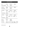
5000 SERIES INSTALLATION PROGRAMMING SHEET (X represents factory setting)
***************************************************************************************************
1
2
3
4
5
6
7
8
P0E
INSTANT
.
X
X
X
X
X
X
X
P1E
DELAY
X
.
.
.
.
.
.
.
P2E
HANDOVER
.
.
.
.
.
.
.
.
P3E
SECOND DELAY
.
.
.
.
.
.
.
.
P4E
24 HR. AUDIBLE
.
.
.
.
.
.
.
.
P5E
24 HR. SILENT
.
.
.
.
.
.
.
.
1
2
3
4
5
6
7
8
P 10 E
1 TRIGGER
X
X
X
X
X
X
X
X
P 11 E
2 TRIGGER
.
.
.
.
.
.
.
.
.
.
.
.
.
.
.
.
1
2
3
4
5
6
7
8
.
.
.
.
.
.
.
.
1
2
3
4
5
6
7
8
.
.
.
.
.
.
.
P 12-19 E VIBRATION
P 20 E
LOCKOUT
P 21 E
MISCELLANEOUS
(See page 15 to 17)
.
P 22 E
ALARM RESET TIME
(In minutes)
10 Min. (Default)
X = DEFAULT SETTING
CLIENT PROGRAM SUMMARY (See 5000 series user book for details)
*********************************************************************
P1E
MASTER CODE
P2E
USER CODE 2
P3E
USER CODE 3
P4E
USER CODE 4
P5E
ENTRY DELAY TIME
20 Sec. (Default)
P6E
EXIT DELAY TIME
60 Sec. (Default)
P7E
MONITOR MODE TYPE (1 to 4)
P8E
MONITOR ZONES
P9E
AUX. OUTPUT ZONES
Page 21
5000 Series Panel 8 Zone Version 3
INSTALLATION PROGRAMMING (Program light flashing)
P0E zone E
P1E zone E
P2E zone E
P3E zone E
P4E zone E
P5E zone E
P10E zone E
P11E zone E
P12E zone E
to
P19E zone E
P20E zone E
P21E option E
P22E time E
Exit Installation mode
Instant
Delay
Handover
Long Delay. Entry time same as Exit time
24hr audible
24hr silent
Single trigger zones (1-8 default)
Double trigger zones
Vibration sensor. Highest sensitivity
Vibration sensor. Lowest sensitivity
Conditional lockout (leds off) Lockout (leds on)
1. Disable Keyswitch entry/exit restriction
2. Enable Arm via Code
3. Disable Auto exclude (full alarm at end of exit time)
4. Disable entry warning beeps (silent entry time)
5. Enable silent Panic alarms
6. Enable silent other alarms (except 24hr & Fire)
7. Enable Monitor modes 1 & 3 to trigger dialler
Siren run time in minutes (1-99)
PE
CLIENT PROGRAMMING (Program light on steady)
P1E code E code E
Code 1 (Master Code)
P2E code E code E
Code 2
P3E code E code E
Code 3
P4E code E code E
Code 4
Codes can be 3-6 digits in length, but cannot start with a 0
P5E time E
P6E time E
P7E option E
P8E zone E
P9E zone E
Exit Client mode
Entry time in seconds (1-99)
Exit time in seconds (1-99)
1. Entry delay the full alarm
2. 2 seconds siren and sonalert
3. Immediate full alarm
4. Zone number pulsed via sonalert
Monitor zones
Auxiliary zones
PE
To re-enter Client program mode
P Master Code E
To re-enter Installation mode
P 000000 E
Note: Entry to Installer mode can only be made while in Client mode
Normal operating mode.
Battery and Mains light ON