1
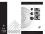
ceiling
mount
I N S T A l l ati o n
G u i d e
DESIGNER AESTHETICS
AUDIOPHILE PERFORMANCE
9901198-RevA-CM-SpkManual-V6a.indd 1
8/17/11 7:13 PM
LEFT/CENTER/RIGHT CEILING-MOUNT LOUDSPEAKERS
CONGRATULATIONS!
Thank you for choosing the Niles CM Loudspeaker Series. With proper
installation, use, and care, your loudspeakers will deliver years of listening
enjoyment. Niles manufactures the industry’s most comprehensive line of
custom installation components and accessories. For information on our
complete product assortment, please visit us at: www.nilesaudio.com.
TABLE OF CONTENTS
Introduction3
Features and Benefits
3
Parts Guide
4
Installation Considerations
4
Installing the Loudspeakers
6
Switch Adjustments
8
Painting the Grilles
8
Installing the Grilles
8
Applications9
CM7
CM8
CM7
CM8
CM7
CM8
CM7
SURROUND EFFECTS CEILING-MOUNT LOUDSPEAKERS
CM7
STEREO INPUT CEILING-MOUNT LOUDSPEAKERs
CM7
WWW.NILESAUDIO.COM
9901198-RevA-CM-SpkManual-V6a.indd 1-2
NILES AUDIO – 1-800-BUY-HIFI – 1-760-710-0992
CM8
2
8/17/11 7:14 PM
INTRODUCTION
PARTS GUIDE
Niles CM Loudspeakers deliver an uncompromising combination of designer
oriented aesthetics, superb sound performance, and ease of installation. Small
footprint and low profile, MicroThin™ magnetically attached grilles provide the
look that today’s homeowners desire. Available in 7” and 8” versions, there are
left/center/right, surround effects, and stereo input models to satisfy applications
ranging from advanced home theaters to distributed audio systems.
PACKAGE CONTENTS FOR:
FEATURES AND BENEFITS
PACKAGE CONTENTS FOR:
DESIGNER AESTHETICS
(2) Niles CM7FX loudspeakers, (2) Magnetically attached round grilles, (2) Hole
templates with painting standoffs, (1) Owner’s manual, (1) Warranty card
Magnetically attached MicroThin™ round speaker grilles ensure a clean,
unobtrusive designer appearance that blends with the room’s aesthetics. Optional
square grilles provide added design flexibility.
Cm7BG, Cm7mP, Cm7PR, Cm7Hd, Cm7sI, Cm8mP, Cm8PR,
Cm8Hd and Cm8sI
(1) Niles CM loudspeaker, (1) Magnetically attached round grill, (1) Hole template
with painting standoffs, (1) Owner’s manual, (1) Warranty card
Cm7FX
INSTALLATION CONSIDERATIONS
Recommended tools for installation:
INSTALLATION EASE
• Cordless screwdriver
• Measuring tape
• Painters tape
Three patent-pending, spring tensioned mounting clamps permit quick installation
and compensate for uneven mounting surfaces and varied environmental
conditions. Weather-resistant construction enables installation in moist areas such
as bathrooms or outdoors under eaves.
• One inch #2 Phillips tip
• Stud finder
• Drop cloth
• 1/8” Drill bit
• Spackle
• Drywall saw
• Wire stripper
• Optional - a 24” x 24”
piece of R19 insulation
• Laser plumb bob
• Cable ties
INSTALL WITH CONFIDENCE
• 12” -14” Coat hanger wire
• Pencil
The best-built loudspeakers deserve the best protection—the Niles Lifetime
Limited Warranty.
7” LOUDSPEAKERS
These require an 8-1/2” (21.6 cm)
diameter hole opening and a
minimum of 4-3/8” (11.1 cm)
depth when measured from the
exterior face of the drywall. To the
sides of the hole you will need 1”
(2.54 cm) for the mounting tabs to
clamp the speaker to the drywall.
CM7 3-5/16" (8.4 cm)
CM8 4-1/8" (10.5 cm)
Depth Behind Drywall
Assuming 5/8" drywall
CM7 8-1/2” (21.6 cm)
CM8 9-3/4” (24.8 cm)
Diameter Hole Opening
8” LOUDSPEAKERS
3
9901198-RevA-CM-SpkManual-V6a.indd 3-4
These require a 9-3/4” (24.8 cm)
diameter hole opening and depth
of 4-3/4” (12.1 cm) from the
exterior face of the drywall. To the Figure 1. Required dimensions for installation in ceiling.
sides of the hole you will need 1”
(2.54 cm) for the mounting tabs to clamp the speaker to the drywall.
(continued on next page)
WWW.NILESAUDIO.COM
NILES AUDIO – 1-800-BUY-HIFI – 1-760-710-0992
4
8/17/11 7:14 PM
INSTALLATION CONSIDERATIONS
INSTALLING THE LOUDSPEAKERS
continued
NOTE: Be very careful when locating the speakers. Verify all locations are
clear of obstructions BEFORE cutting the first hole.
Each speaker requires two-conductor wiring of sufficient gauge. The gauge
depends on the length of the wire. For recommendations, please refer to (Figure 2).
(Stereo Input loudspeakers require four-conductor wiring).
Distance from speaker to amplifier
Wire Gauge
Less than 80 feet
16
80 to 200 feet
14
More than 200 feet
12
Figure 2. Speaker Wire Gauge Guide
When running loudspeaker wire inside walls or ceilings, use special jacketed
cable (CL-2 or CL-3 rating) to protect the wire and for fire prevention. In some
municipalities, conduit is required. For a trouble-free installation, low voltage wire
such as loudspeaker wire must be in accordance with the National Electrical Code
and any applicable provisions of the local building code. If you are unsure of the
correct installation techniques, wire jacket, or type of conduit to use, consult a
professional audio/video installer, building contractor, or the local building and
inspection department.
* Not for use with SI Speakers
It is often easier to lay the speakers out on the floor and then transfer the
locations to the ceiling with a laser plumb bob. If you are using new construction
brackets, place string across the centers of the bracket to provide a way to align
the bracket to the laser. Remember, you will need 1” (2.54 cm) to the sides of the
mounting hole for the mounting clamps to secure the speaker to the drywall.
1. Once you have determined a possible position for the hole cutout, drill a
1/8” pilot hole just barely through the ceiling (1/2” to 5/8” deep in most
homes) in the center of your proposed loudspeaker location. BE VERY
CAREFUL NOT TO DRILL THROUGH EXISTING WIRES, PIPES, OR
STRUCTURE. IF YOU FEEL ANY EXTRA RESISTANCE AS YOU ARE
DRILLING, STOP.
2. Cut a foot-long piece of coat hanger. Bend the wire (creating a right angle)
leaving 5-1/2” at one end (this allows for the extra width of the mounting
dogs). Poke the “L-shaped” wire into the pilot hole and turn it
in a complete circle and move it into the ceiling cavity to make sure
you have approximately 4-3/8” of depth for the CM7 Series and 4-3/4”
of depth for the CM8 Series loudspeakers. If the wire’s movement is
obstructed by anything, fill the hole(s) with spackle and try another
location. (If there is any risk of uninsulated electrical connections within
the ceiling area, use insulating gloves or other materials or consult with an
installation professional before proceeding).
3. If the coat hanger moves freely in a complete circle and you have
sufficient depth, tape the template to the ceiling and proceed to layout the
other speakers. Once you are comfortable with all speaker locations, use
a pencil to lightly outline the circular template.
4. Drill the starting point of your cut with a 1/4” bit.
5. If you are cutting drywall, use a sheetrock or keyhole saw. Cut the hole
with the saw at a 45° angle. That way the drywall section can be replaced
cleanly if there is an unseen obstruction behind the wall. IMPORTANT: BE
VERY CAREFUL NOT TO SAW THROUGH EXISTING WIRES, PIPES,
OR STRUCTURE. IF YOU FEEL EXTRA RESISTANCE AS YOU ARE
CUTTING, STOP.
NOTE: Do not install loudspeakers before the drywall has been completely
finished and painted.
(continued on next page)
5
9901198-RevA-CM-SpkManual-V6a.indd 5-6
WWW.NILESAUDIO.COM
NILES AUDIO – 1-800-BUY-HIFI – 1-760-710-0992
6
8/17/11 7:14 PM
INSTALLING THE LOUDSPEAKERS
SWITcH ADJUSTMENTS
continued
6. P
rep the speaker wire by stripping 1/4”-1/2” from each speaker lead.
Twist the strands or tin the leads with solder to ensure there are no stray
strands that could short and possibly harm the amplifier.
7. If you’ve chosen to use insulation behind the loudspeaker, place it
through the hole and center it on the opening. If using paper-backed
insulation, it should be placed so that the paper side is away from the
loudspeaker.
8.The speaker has black and red
spring-loaded connectors (Figure 3).
Black is for the negative (-) wire and
red for the positive (+). It is important
to observe correct wiring polarity.
This is especially important for the
Stereo Input (SI) Loudspeaker. If you
have wire other than black and red,
make sure you connect it the same
on the amplifier end as the speaker
end. Failure to do so will adversely
affect the loudspeakers’ performance.
Figure 3. Spring-loaded speaker wire
connectors.
NOTE: Do not carry the speaker
by the tweeter or tweeter
bridge. This may damage the
speaker.
9901198-RevA-CM-SpkManual-V6a.indd 7-8
(PR and HD models)
The three-position tweeter switch allows you to adjust the high frequency output
of the loudspeaker to compensate for room acoustics. The center position,
marked 0, does not affect the tweeter’s output. Moving the switch to the –
position reduces the tweeter output by 3 dB to compensate for bright rooms
(tile or wood floors, sparse furnishing, tall ceilings). Moving the switch to the
+ position increases the tweeter output by 3 dB to compensate for absorptive
rooms (carpeting, lots of drapery, plush furniture, etc.).
Diffuse / Direct Switch
(CM7FX)
Use the Diffuse setting for movies and general music listening since most films
are mixed using non-localized surround effects and music is usually recorded in a
favorable acoustic environment. Use the Direct setting for discrete multi-channel
recordings that equally emphasize front and surround sounds. For 7.1-channel
surround sound systems, use the Diffuse setting on the side effects loudspeakers
and the Direct setting for the rear effects loudspeakers.
PAINTING THE GRILLES
9.Once the speaker wires are
connected, carefully slide the
loudspeaker into the opening hole
(Figure 4). While holding the speaker
in place, tighten the mounting screws
to secure the speaker to the drywall.
We recommend using a motorized
screwdriver. Be careful not to over
tighten. The CM loudspeakers feature
spring loaded mounting clamps that
allow the speaker to remain flush
with the ceiling, even if the
drywall shifts or expands.
7
Treble Switch
The CM loudspeaker grilles can be painted without priming, but the fabric scrim
must first be removed. The installation template has die cut standoffs that can be
used to position the grille off the ground while painting. Use several light coats
sprayed from different sides and angles to cover all surfaces and not fill in any
holes. If you do fill some holes, use compressed air to open them before the paint
dries. It may be helpful to slightly dilute the paint to prevent it from clogging the
grille holes.
INSTALLING THE GRILLES
The Niles MicroThin™ speaker grille installs magnetically over the speaker.
Carefully center the grill over the speaker and let the magnets do their work,
verifying that the grill sets flush against the ceiling at all edges.
Figure 4. Installing a
CM loudspeaker.
Mounting clamps require
1” clearance to the sides
of the hole opening
WWW.NILESAUDIO.COM
NILES AUDIO – 1-800-BUY-HIFI – 1-760-710-0992
8
8/17/11 7:14 PM
APPLICATIONS
APPLICATIONS
Niles CM Loudspeakers are designed to be installed in any standard ceiling.
When choosing a location, thought should be given to the sound coverage of the
loudspeaker, and ease of running the speaker wire. Niles manufactures a large
variety of speaker models for many different applications, with special models for
shallow depth ceilings, models with Rear Wave Enclosures to minimize any sound
bleeding through to adjacent rooms, etc.
SINGLE SPEAKER STEREO INPUT APPLICATIONS
(CM7SI, CM8SI)
STEREO SOUND APPLICATIONS
The best stereo effect will be achieved if both
loudspeakers are at an equal distance from the
listening area. Ideally all loudspeakers should
be on the same horizontal plane (Figure 6). Avoid
installing loudspeakers near corners to prevent
a “boomy” or diffracted sound. Also note that
the lower the ceiling, the closer the loudspeaker
should be placed to the listener.
Side Surround Effects (CM7FX) – Position
surround effects loudspeakers to the sides
of the listening area with the tweeters in-line
with the listener. The tweeters should point
to the front and rear of the room (Figure 7).
Rear Surround Effects (CM7FX) – Position
surround effects loudspeakers behind the
listening area, to the inside of the front left
and right speakers. The tweeters should
point to the sides of the room (Figure 7).
Stereo Input loudspeakers are ideal for small rooms where positioning two
loudspeakers is not practical. Examples would be a small kitchen, bathroom,
hallway, or small bedroom. Locate the loudspeaker as close to the center of the
room as possible for the most even distribution of sound (Figure 8). Avoid installing
the loudspeaker near a corner to prevent a “boomy” or diffracted sound.
8'
8'
3-6'
3-6'
Figure 6. Stereo Sound Application.
HOME THEATER
APPLICATIONS
Left/Center/Right – Position the center
channel loudspeaker directly over the
television, with the left and right speakers
equidistant from the center. The separation
between the left and right should not be
more than the distance to the primary
seating area (Figure 7).
continueD
LCR
LCR
LCR
Figure 8. Single Loudspeaker Stereo Input Application.
FX
FX
FX
Critical
Listening
Position
FX
Figure 7. Home Theater Application.
(continued on next page)
9
9901198-RevA-CM-SpkManual-V6a.indd 9-10
WWW.NILESAUDIO.COM
NILES AUDIO – 1-800-BUY-HIFI – 1-760-710-0992
10
8/17/11 7:14 PM
SPECIFICATIONS
Model
Woofer
Tweeter /
Midrange
Recommended
Amplifier Power
Normal
Impedance
Frame Dimensions
with Grille
Hole Cut-Out
Dimensions
Depth (5/8”
Drywall Ceiling)
CM7BG
7”
Polypropylene
woofer cone
13mm
Kaladex
10-75 watts
8 ohm nominal;
6 ohm minimum
9-7/8” (25.1 cm)
8-1/2”
(21.6 cm)
3-3/4” (9.5 cm)
BY PHONE (IN USA)
7” Black
Glass Fiber
Tight Weave
woofer cone
1” Ultra Silk
7“ Black
Glass Fiber
Tight Weave
woofer cone
1” Teteron
CM7HD
7” Aluminum
Ceramic
woofer cone
1” Nano
Al/Cer/Tita
CM7SI
7” Black
Glass Fiber
Tight Weave
woofer cone
Dual 1”
Ultra Silk
CM7MP
CM7PR
10-130 watts
8 ohm nominal;
6 ohm minimum
9-7/8” (25.1 cm)
8-1/2”
(21.6 cm)
3-3/4” (9.5 cm)
1-800-BUY-HIFI (289-4434)
BY PHONE (OUTSIDE USA)
8 ohm nominal;
6 ohm minimum
9-7/8” (25.1 cm)
10-160 watts
8 ohm nominal;
6 ohm minimum
10-130 watts
8 ohm nominal;
6 ohm minimum
10-130 watts
8-1/2”
(21.6 cm)
3-3/4” (9.5 cm)
9-7/8” (25.1 cm)
8-1/2”
(21.6 cm)
3-3/4” (9.5 cm)
9-7/8” (25.1 cm)
8-1/2”
(21.6 cm)
1-760-710-0992
Customer service hours
8:00 AM to 5:30 PM PT
Technical support hours
6:00 AM to 4:00 PM PT
3-3/4” (9.5 cm)
on the web
w w w.nilesaudio.com
7” Black
Glass Fiber
Tight Weave
woofer cone
Dual 1”
Teteron
CM8MP
8” Black
Glass Fiber
Tight Weave
woofer cone
1” Ultra Silk
10-140 watts
8 ohm nominal;
6 ohm minimum
11-3/8” (28.9 cm)
9-3/4”
(24.76 cm)
4-1/8” (10.5 cm)
CM8PR
8” Black
Glass Fiber
Tight Weave
woofer cone
1” Teteron
10-140 watts
8 ohm nominal;
6 ohm minimum
11-3/8” (28.9 cm)
9-3/4”
(24.76 cm)
4-1/8” (10.5 cm)
CM8HD
8” Aluminum
Ceramic
woofer cone
1” Nano
Al/Cer/Tita
10-160 watts
8 ohm nominal;
6 ohm minimum
11-3/8” (28.9 cm)
9-3/4”
(24.76 cm)
4-1/8” (10.5 cm)
CM8SI
8” Black
Glass Fiber
Tight Weave
woofer cone
Dual 1”
Teteron
10-130 watts
8 ohm nominal;
6 ohm minimum
11-3/8” (28.9 cm)
9-3/4”
(24.76 cm)
4-1/8” (10.5 cm)
CM7FX
10-140 watts
8 ohm nominal;
6 ohm minimum
9-7/8” (25.1 cm)
8-1/2”
(21.6 cm)
3-3/4” (9.5 cm)
email technical support
[email protected]
11
9901198-RevA-CM-SpkManual-V6a.indd 11-12
email for product suggestions
WWW.NILESAUDIO.COM
[email protected]
NILES AUDIO – 1-800-BUY-HIFI – 1-760-710-0992
12
8/17/11 7:14 PM
1969 Kellogg Avenue, Carlsbad, CA 92008
1-760-710-0992
1 - 8 0 0 - B U Y- H I F I – w w w. n i l e s a u d i o . c o m
©2011 The AVC Group, LLC. All rights reserved. Niles and the Niles logos, UltraSilk and Blending
High Fidelity and Architecture are registered trademarks of The AVC Group, LLC. MicroThin is a
trademark of The AVC Group, LLC. All other trademarks are the property of their respective owners.
We reserve the right to change specifications, descriptions and prices without notice. The technical and
other information contained herein is not intended to set forth all technical and other specifications.
Designed and engineered in the USA. 9901198 Rev A
9901198-RevA-CM-SpkManual-V6a.indd 13
8/17/11 7:14 PM