1
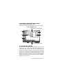
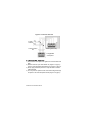
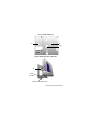
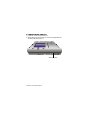
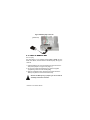
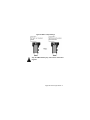
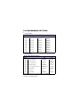
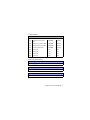
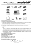
for
DNE-K07
Reference and Installation Manual
DGP-641
TABLE OF CONTENTS
INTRODUCTION.............................................................................2
Specifications ......................................................................................... 3
Navigation............................................................................................... 3
INSTALLATION ..............................................................................4
Viewing Angle......................................................................................... 4
Keypad Cover Clearance ....................................................................... 4
Mounting the Metal Wall Plate................................................................ 5
Connecting Grafica................................................................................. 5
Mounting Grafica .................................................................................... 6
Unmounting Grafica................................................................................ 8
PROGRAMMING ............................................................................9
Entering Module Programming Mode..................................................... 9
Programming Methods ......................................................................... 10
SYSTEM OPTIONS ......................................................................11
Partition Assignment............................................................................. 11
Display Code Entry............................................................................... 11
Display Exit Delay................................................................................. 11
Display Entry Delay .............................................................................. 12
Confidential Mode................................................................................. 12
Exit Delay Beep .................................................................................... 13
Keypad Tamper .................................................................................... 13
Beep on Trouble ................................................................................... 14
Confidential Mode Timer ...................................................................... 15
Download from the Memory Key .......................................................... 15
Copy to Memory Key ............................................................................ 16
PROGRAMMING SECTIONS.......................................................18
1.0 INTRODUCTION
Grafica is the most advanced keypad and communication device in
the security industry. Developed to resolve operational flaws with
security system keypads, Grafica offers the ability to view zone
locations on a floor plan drawing through its graphic LCD screen and
provides simple menu-driven commands that eliminate the need of
user manuals thus reducing training time to a minimum. The software
contains over 120,000 lines of code and was developed in
collaboration with end users resulting in a keypad that is intuitive and
guides the user to the next logical step.
Other software-related features include downloadable tunes and
bitmaps for many functions, a smart search engine for users and
zones, alarm clock, and on-site upgradable firmware. Grafica’s
design uses the latest and most sophisticated technologies available,
such as metallic colour finishing, laser-trimmed text, flexible and
multi-layered PCBs and SMD fine-pitch components. With its
shocking, ultra-modern style, Grafica sets a new milestone for
communication devices in the security industry for years to come.
1.1 SPECIFICATIONS
Power input:
Power indication:
Locate indication:
Bus fault indication:
Anti-tamper switch:
Display:
Compatibility:
Typically 12 to 16 Vdc, 130mA maximum.
Blue LED on.
Blue LED flashes.
Fault indication message will appear on
screen.
Yes.
Film Super Twisted Nematic.
(Black and white contrast). 128 X 128 pixels.
Under ESD conditions the screen may go
blank. To reset the screen press any key.
DigiplexNE version 1.3 or higher.
Winload version 2.2 or higher.
NEware Version 2.0.
1.2 NAVIGATION
Grafica’s three action keys represent selections that appear directly
above the key on the screen. They enable you to move forward/back,
toggle the status of options and save choices. The scroll keys enable
you to highlight and select options throughout the various menus.
Figure 1: Key Overview
Action
Keys
Scroll
Keys
DigiplexNE Grafica Keypad Module 3n
2.0 INSTALLATION
2.1 VIEWING ANGLE
The Grafica keypad’s graphic LCD is best viewed from a direct angle
between a range of 20° and -10° (Figure 2). Be sure to install the
Grafica keypad at a height and in a direction that provides the best
viewing angle.
Figure 2: Viewing Angle
+20°
0°
-10°
2.2 KEYPAD COVER CLEARANCE
Grafica’s
keypad
cover
requires sufficient space in
order to open properly. Ensure
a clearance of approx 3.5”
(9cm) between the open
keypad cover and possible
obstructions such as a
light switch (Figure 3).
Figure 3: Cover Clearance
3.5” (9cm)
Light
switch
4 Reference & Installation Manual
2.3 MOUNTING THE METAL WALL PLATE
1) Place metal wall plate to desired position.
2) Drill and insert screws into holes labeled “A” as shown in Figure 3.
Figure 3: Metal Wall Plate
A (Used also for electrical box)
A
A
B
B
C (for clip)
A
A (Used also for electrical box)
2.4 CONNECTING GRAFICA
You can connect Grafica to the DigiplexNE control panel’s
communication bus in a star and/or daisy chain configuration. The
communication bus consists of four wires that provide power and
two-way communication between the control panel and all modules
connected to it. Connect the four terminals labelled RED, BLK, GRN
and YEL of the module to the corresponding terminals on the control
panel as shown in Figure 4 on page 6. Please refer to the DigiplexNE
Installation & Reference Manual for maximum allowable installation
distance from the control panel.
DigiplexNE Grafica Keypad Module 5n
Figure 4: Connection Overview
To other
modules
YEL
GRN
BLK
RED
Communication--bus
Grafica (partial view)
To DigiplexNE
control panel
2.5 MOUNTING GRAFICA
1) Place Grafica’s back plate flush against the mounted metal wall
plate.
2) Slide the Grafica’s open slots labeled “D” (Figure 5 on page 7)
onto the metal wall plate’s tabs labeled “B” (Figure 6 on page 7).
3) Gently apply downward pressure to snap the Grafica onto the
metal wall plate.
4) You may insert an optional screw under Grafica keypad through
the space in the metal wall plate’s left tab (Figure 6 on page 7).
6 Reference & Installation Manual
Figure 5: Grafica Back Plate
D
D
Clip
Figure 6: Mounting Grafica to Wall Plate
B
Metal
wall plate
Optional screw inserted here
DigiplexNE Grafica Keypad Module 7n
2.6 UNMOUNTING GRAFICA
1) If required, remove the optional screw.
2) Gently lift the unit upwards with your hands until it separates from
the metal wall plate (Figure 7).
Figure 7: Unmounting the Grafica
Metal wall plate
8 Reference & Installation Manual
3.0 PROGRAMMING
Enter the Module Programming Mode, enter the desired section
followed by the required data. When programming the Grafica, use
the keypad’s programming sheets (in the DigiplexNE Modules’
Programming Guide). Refer to “Programming Sections” in section
5.0 to keep track of which sections were programmed and how. We
strongly recommend you read this entire manual before you begin
programming.
Grafica can also be programmed using the WinLoad Security
System Management Software. For more information, refer to the
WinLoad instructions or visit our Web site at www.paradox.ca.
Floor plans, tunes and graphics can be downloaded to
Grafica using Winload V2.2 or higher and NEware V2.0 or
higher.
3.1 ENTERING MODULE PROGRAMMING MODE
Like all other keypads in the system, Grafica is programmed through
the control panel. To do so, you must first enter the Module
Programming Mode:
Step 1:
Step 2:
Step 3:
Step 4:
Step 5:
Step 6:
From Normal Mode press and hold the [0] key.
Enter the [INSTALLER CODE] (by default 000000).
Enter section [4003].
Enter Grafica’s 8-digit [SERIAL NUMBER].
Enter the 3-digit [SECTION] you want to program.
Enter the required [DATA].
The control panel will then redirect all programming to the selected
Grafica keypad. Use the scroll and action keys to navigate through
desired sections.
DigiplexNE Grafica Keypad Module 9n
The serial number is located on Grafica’s PCB or enter
section [0000] in Step 3 to view Grafica’s version and serial
number.
3.2 PROGRAMMING METHODS
The following methods can be used when programming the Grafica
keypad:
3.2.1 FEATURE SELECT PROGRAMMING
You can program sections by enabling or disabling options.
Within these sections, keys [1] to [8] or scroll keys represent a
specific Grafica option. Use the scroll keys to highlight the
desired option and press the corresponding action key to
enable or disable the option. An “X” will appear to indicate that
the option is enabled. Press the appropriate action key to save
the status of selected option(s).
3.2.2 DECIMAL PROGRAMMING
Some sections require the entry of a decimal value. For this
method, any value from 000 to 255 can be entered.
3.2.3 HEXADECIMAL PROGRAMMING
Some sections require the entry of a hexadecimal values [A]
to [F]. Press the “#” key to scroll through these values. If the
value is left unchanged for a second or two, Grafica will
automatically select it, and move forward to the next digit.
10 Reference & Installation Manual
4.0 SYSTEM OPTIONS
The following sections detail the options that can be programmed for
Grafica.
4.1 PARTITION ASSIGNMENT
SECTION [001]: OPTIONS [1] TO [8]
Each keypad in the system can be assigned to one or more
partitions. In section [001], options [1] to [8] represent partitions 1
through 8 respectively. To assign the keypad to a partition, enable the
option that corresponds to the desired partition. By default, partitions
1 to 8 are enabled.
4.2 DISPLAY CODE ENTRY
SECTION [002]: OPTION [1]
This option displays the digits of the User Access Codes on the
graphic LCD as they are entered.
Option [1] OFF = Digits are replaced by a *. (Default).
Option [1] ON = Access Code digits will be displayed.
4.3 DISPLAY EXIT DELAY
SECTION [002]: OPTION [2]
Based on the user's needs, an Exit Delay Timer can be programmed
to provide the user time to exit the partition before the system is
armed. If this option is enabled, the Exit Delay Timer's countdown will
appear on the graphic LCD screen next to the hour-glass icon.
Option [2] OFF = Exit delay time will not appear.
Option [2] ON = Exit delay time will appear (Default).
DigiplexNE Grafica Keypad Module 11n
4.4 DISPLAY ENTRY DELAY
SECTION [002]: OPTION [3]
Based on the user's needs, an Entry Delay Timer can be
programmed to provide the user time to enter their User Access
Code before the alarm is triggered. If this option is enabled, the Entry
Delay Timer's countdown will appear on the graphic LCD screen next
to the hourglass icon.
Option [3] OFF = Does not display Entry Delay Timer.
Option [3] ON = Displays Entry Delay Timer (Default).
4.5 CONFIDENTIAL MODE
SECTION [002]: OPTIONS [4] AND [5]
This option is not for UL Installations.
If the Confidential Mode is enabled and no actions are performed on
the Grafica keypad for a period of time, the graphic LCD will display
the time, date and all LEDs on the keypad will turn off until either a
key is pressed, or an access code is entered. The period of time in
which no action is performed is defined by the Confidential Mode
Timer on page 15.
12 Reference & Installation Manual
Grafica will go from Confidential Mode into Normal Mode once a key
is pressed or a code is entered. In normal mode, Grafica displays the
date, time, as well as the status of open zones for every partition that
the keypad is assigned. In addition, Alarm Memory Display,
Bypassed zones and the Trouble Display can be displayed.
SECTION [002]: OPTION [4]
Option [4] OFF = Normal Mode (Default).
Option [4] ON = Confidential Mode.
SECTION [002]: OPTION [5]
Option [5] OFF = Exit confidential mode by entering an access code
(Default).
Option [5] ON = Exit confidential mode by pressing a key.
The default option in Section [002] Option 5 (default) will
only work if option [4] in section [002] is enabled.
4.6 EXIT DELAY BEEP
SECTION [002]: OPTION [6]
The keypad can beep once every second or play a selected song
during the Exit Delay Timer. During the final 10 seconds only the
beep tone will be heard (at a faster interval) to provide a final warning
before the area is armed.
Option [6] OFF = Exit Delay beep disabled.
Option [6] ON = Exit Delay beep enabled (default).
4.7 KEYPAD TAMPER
SECTION [002]: OPTION [8]
When tamper is enabled and the keypad's anti-tamper switch is
triggered, the keypad will send a Tamper report to the control panel
DigiplexNE Grafica Keypad Module 13n
via the communication bus.
Option [8] OFF = Grafica’s anti-tamper switch is disabled. (Default)
Option [8] ON =Grafica’s tamper is enabled.
4.8 BEEP ON TROUBLE
SECTION [003]: OPTIONS [1] TO [4]
Potential troubles have been sorted into groups. With these options
enabled, the keypad will emit an intermittent beep tone whenever a
trouble condition occurs from one of the Trouble Groups. The
intermittent beep will remain activated until the user enters the
Trouble Display or if the trouble is resolved. For a list of troubles, see
the DigiplexNE Reference and Installation Manual. The intermittent
beep will be re-initialized whenever the trouble condition reoccurs. By
default, options [1] to [4] are OFF.
4.8.1 SYSTEM AND CLOCK TROUBLE BEEP
SECTION [003]: OPTION [1]
Option [1] OFF = Beep disabled (Default).
Option [1] ON = Beep on: System Troubles and Clock Loss.
4.8.2 COMMUNICATOR TROUBLE BEEP
SECTION [003]: OPTION [2]
Option [2] OFF = Beep disabled (Default).
Option [2] ON = Beep on: Communicator Troubles.
14 Reference & Installation Manual
4.8.3 MODULE AND BUS TROUBLE BEEP
SECTION [003]: OPTION [3]
Option [3] OFF = Beep disabled (Default).
Option [3] ON = Beep on: Module and Bus Troubles.
4.8.4 ALL ZONE TROUBLE BEEP
SECTION [003]: OPTION [4]
Option [4] OFF = Beep disabled (Default).
Option [4] ON = Beep on: all Zone Troubles.
4.9 CONFIDENTIAL MODE TIMER
SECTION [004]
Section [004] determines the amount of time without action before
the keypad enters Confidential Mode, (see page 12). The
Confidential Mode Timer can be set from 005 seconds to 255
seconds. Default: 120 seconds.
4.10 DOWNLOAD FROM THE MEMORY KEY
SECTION [100]
Use this section to download Grafica’s section [001] to [004], all
zone labels, area labels, and user labels from the Memory Key. To
download the contents:
1) Insert the Memory Key onto the keypad’s connector (see Figure
8 on page 16).
2) To download the contents of the Memory Key, enter the keypad’s
programming mode and enter section [100].
3) When the keypad emits a confirmation beep, wait five seconds
and remove the Memory Key after the second confirmation beep.
DigiplexNE Grafica Keypad Module 15n
Figure 8: Memory Key Connector
(partial view)
4.11 COPY TO MEMORY KEY
SECTION [110]
Use this section to copy Grafica sections [001] to [004], all zone
labels, area labels, and user labels to the Memory Key. To copy the
contents:
1) Insert the Memory Key onto the keypad’s connector. Ensure the
write protect jumper is on (figure 9 on page 17).
2) To copy the contents to the Memory Key, enter the keypad’s
programming mode and enter section [110].
3) After the confirmation beep, wait five seconds and remove the
Memory Key after the second confirmation beep.
Remove the Memory Key’s jumper if you do not wish to
accidently overwrite its contents.
16 Reference & Installation Manual
Figure 9: PMC-3 Jumper Settings
Only the PMC-3 Memory Key will function with Grafica
keypads.
DigiplexNE Grafica Keypad Module 17n
5.0 PROGRAMMING SECTIONS
U= Default Setting
Section [001]: Keypad Partition Assignment
Option
OFF
[1]
PARTITION 1
[2]
PARTITION 2
[3]
PARTITION 3
[4]
PARTITION 4
[5]
PARTITION 5
[6]
PARTITION 6
[7]
PARTITION 7
[8]
PARTITION 8
.DISABLED
.DISABLED
.DISABLED
.DISABLED
.DISABLED
.DISABLED
.DISABLED
.DISABLED
ON
UENABLED
UENABLED
UENABLED
UENABLED
UENABLED
UENABLED
UENABLED
UENABLED
U= Default Setting
Section [002]: General Options 1
Option
OFF
UDISABLED
[1]
DISPLAY CODE ENTRY
[2]
DISPLAY EXIT DELAY
[3]
DISPLAY ENTRY DELAY
.DISABLED
[4]
CONFIDENTIAL MODE
UDISABLED
[5]
TO EXIT CONFIDENTIAL MODE *
UENTER CODE
[6]
EXIT DELAY BEEP
[7]
FUTURE USE
.N/A
[8]
KEYPAD TAMPER
UDISABLED
.DISABLED
.DISABLED
ON
.ENABLED
UENABLED
UENABLED
.ENABLED
.PRESS KEY
UENABLED
.N/A
.ENABLED
* Must be enabled through Option [4] in section [002] first.
18 Reference & Installation Manual
U= Default Setting
Section [003]: Beep on Trouble
Option
OFF
ON
[1]
SYSTEM & CLOCK TROUBLE
BEEP
UDISABLED
.ENABLED
[2]
COMMUNICATOR TROUBLE BEEP
UDISABLED
.ENABLED
[3]
MODULE & BUS TROUBLE BEEP
UDISABLED
[4]
ALL ZONE TROUBLE BEEP
UDISABLED
[5]
FUTURE USE
[6]
FUTURE USE
[7]
FUTURE USE
[8]
FUTURE USE
.ENABLED
.ENABLED
.N/A
.N/A
.N/A
.N/A
.N/A
.N/A
.N/A
.N/A
120 seconds Default Setting
Section [004]: Confidential Mode Timer
Data
___/___/___
(005 to 255 seconds)
Section [100]: Download From Memory Key
DOWNLOAD DATA FROM MEMORY KEY
Section [110]: Copy to Memory Key
DOWNLOAD DATA TO MEMORY KEY
DigiplexNE Grafica Keypad Module 19n
Warranty
The Seller warrants its products to be free from defects in materials
and workmanship under normal use for a period of one year. Except
as specifically stated herein, all express or implied warranties
whatsoever, statutory or otherwise, including without limitation, any
implied warranty of merchantability and fitness for a particular
purpose, are expressly excluded. Because Seller does not install or
connect the products and because the products may be used in
conjunction with products not manufactured by Seller, Seller cannot
guarantee the performance of the security system. Seller obligation
and liability under this warranty is expressly limited to repairing or
replacing, at Seller's option, any product not meeting the
specifications. In no event shall the Seller be liable to the buyer or
any other person for any loss or damages whether direct or indirect
or consequential or incidental, including without limitation, any
damages for lost profits, stolen goods, or claims by any other party
caused by defective goods or otherwise arising from the improper,
incorrect, or otherwise faulty installation or use of the merchandise
sold.
© 2002 Paradox Security Systems Ltd.
Grafica, DigiplexNE, Winload and NEware are trademarks of
Paradox Security Systems.
20 Reference & Installation Manual
Printed in Canada - 08/2002
GRAFICA-EI01