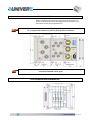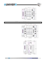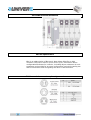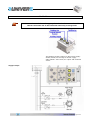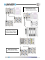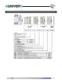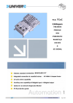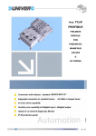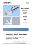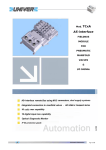
1
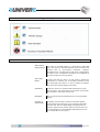
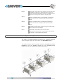
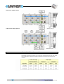
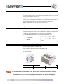
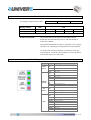
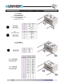
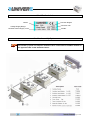
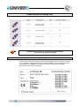
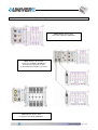
Mod. TCxD DeviceNet FIELDBUS MODULE FOR PNEUMATIC MANIFOLD VALVES & I/O SIGNAL Pg. 1 di 24 INDEX Important note .....................................................................................................................................3 Abbreviation .........................................................................................................................................3 Legend of symbols ...............................................................................................................................4 Terms Definition ...................................................................................................................................4 System descripiton...............................................................................................................................5 Module installation ...............................................................................................................................6 P10 Compact manifold dimentions.......................................................................................................6 P15 Compact manifold dimentions.......................................................................................................7 ISO VDMA manifold dimentions ............................................................................................................8 EDS file specification ............................................................................................................................8 Fieldbus module connectors pin assignement......................................................................................8 Module Power .......................................................................................................................................9 DeviceNet Network connection ............................................................................................................10 DeviceNet I/O Comunication.................................................................................................................11 Terminal network resistor.....................................................................................................................11 How to Set the Module Address............................................................................................................11 Baudrates function mode .....................................................................................................................12 Module Diagnostic and Status indicators..............................................................................................12 Module Specifications...........................................................................................................................13 Valves Coil & Input/Output Slot Allocation............................................................................................14 Digital I/O data mapping ......................................................................................................................14 Manifold valves digital outputs consumes-data mapping .....................................................................14 Auxiliary Digital OUTPUT consumes-data mapping ..............................................................................15 Auxiliary Digital INPUT produces-data mapping ...................................................................................15 Diagnostic function setting and mapping .............................................................................................15 Auxiliary Digital I/O Modules Specifications ..........................................................................................17 Auxiliary Digital I/O Modules Connection ..............................................................................................18 Identification Label ...............................................................................................................................19 Modules Assembly System ...................................................................................................................19 FieldBus Accessories ordering code .....................................................................................................20 Conformity Declaration ........................................................................................................................20 System configuration examples ...........................................................................................................21 Dangers and residual risks ...................................................................................................................23 Dangers caused by Improper use.........................................................................................................23 Correct and incorrect Use.....................................................................................................................23 Frequency of programmed maintenance .............................................................................................23 Instructions regarding removal / elimination of waste materials ..........................................................23 Fieldbus ordering string definition........................................................................................................24 Every conceivable measure has been taken to ensure the correctness and completeness of this documentation. However, as errors can never be fully excluded we would appreciate any information or ideas at any time. /------------/ We wish to point out that the software and hardware terms as well as the trademarks of companies used and/or mentioned in the present manual are generally trademark or patent protected. Pg. 2 di 24 Important note To ensure fast installation and start-up of the units described in this manual, we strongly recommend that the following information and explanations are carefully read and abided by. Personnel Qualification The use of the product detailed in this manual is exclusively geared to specialists having qualifications in PLC programming, electrical specialists or persons instructed by electrical specialists who are also familiar with the valid standards. UNIVER S.p.A. declines all liability resulting from improper action and damage to UNIVER S.p.A. products and third party products due to non-observance of the information contained in this manual. Intended Use For each individual application, the components supplied are to work with a dedicated hardware and software configuration. Modifications are only permitted within the framework of the possibilities documented in the manuals. All other changes to the hardware and/or software and the nonconforming use of the components entail the exclusion of liability on part of UNIVER S.p.A. Please direct any requirements pertaining to a modified and/or new hardware or software configuration directly to UNIVER S.p.A. Applycation Notes Attention Switch off the system prior to working on bus modules! In the event of deformed contacts, the module in question is to be replaced, as its functionality can no longer be ensured on a long-term basis. ESD (Electrostatic Discharge) The modules are equipped with electronic components that may be destroyed by electrostatic discharge. When handling the modules, ensure that the environment (persons, workplace and packing) is well grounded. Avoid touching conductive components, e.g. gold contacts. Attention Identifies information about practices or circumstances that can lead to personal injury or death, property damage, or economic loss. Attentions help you: • identify a hazard • avoid a hazard • recognize the consequence Abbreviation DI Digital Input DO Digital Output I/O Input/Output ID Identifier HW Hardware SW Software LSB Least Significant Digit MSD Most Significant Digit VLS24 Logic & Sensor power supply VA24 Auxiliary Output power supply Pg. 3 di 24 Legend of symbols Terms Definition Auto Device Replacement This refers to the ADR feature of a TCxD device. With ADR active, any device on the DeviceNet link may be removed and replaced with an out-of-the-box checkmark compliant DeviceNet device. The ADR feature will result in downloading the values of the configuration parameters of the EDS file of the removed device to the new device Auto Start Mode A feature that lets the device “up and running” without the prerequisite to configure any of the EDS parameters Using Auto Start Mode will result in a scan list within the adapter that stores the modules identity information. Autobaud A feature in devices on the DeviceNet network that causes them to listen to communications on the network and set their own baudrate to match the network rate. Baudrate Rate of communications between devices on the DeviceNet network Change of State (COS) DeviceNet communications method in which the adapter sends data based on detection of any changed value within the input data. Data is independently received based on a change of state from the sender. Data in both directions can be acknowledged or unacknowledged depending on the runtime configuration of the system. Pg. 4 di 24 Master A DeviceNet network device that initiates communication with DeviceNet slave devices to retrieve data. The master only receives unprompted data when the slave is enabled for COS and there is a change in the device’s operating state. Offline State of the adapter when it is not powered or maintaining normal communication exchanges with other DeviceNet devices Online State of the adapter when it is powered and maintaining normal communication exchanges with other DeviceNet devices Polled DeviceNet communications method in which a module sends data in response to received data. Slave A DeviceNet network device that cannot initiate communication (except when configured with COS enabled) but responds to a DeviceNet master device System descripiton The TCxD is a modular fieldbus slave device for controlling manifold valve and digital input and output which use DeviceNet fieldbus. The system structure here described consists of an MANIFOLD OUTPUT INTERFACE (1), of an FIELDBUS module (2) of an AUXILIARY DI/DO modules (3), the end module (4) completes the system. Pg. 5 di 24 Module installation Before installing the module, verify that all its parts are intact and have not been damaged during transport, pay attention to the overall dimentions. We do recommend to fix the device in the specified hole with M4 screws on a single metal surface to grant a good ground connection The overall length changes according to the numbers of the auxiliary I/O modules used and manifold valves type. P10 Compact manifold dimentions Pg. 6 di 24 P15 Compact manifold dimentions Pg. 7 di 24 ISO VDMA manifold dimentions EDS file specification EDS is an abbreviation of Electronic Data Sheet. EDS file on disk contains configuration data for specific device types, information about configurable attributes for a device, including object addresses of each parameter and provide for an open configuration tool while reading the device information and recognizing the device characteristics. Fieldbus module connectors pin assignement Pg. 8 di 24 Module Power Connect the module to the appropriate DeviceNet network cable The PE connection has to be connected externally to the ground The fieldbus module requires a dual power supply: VLS24 (24Vdc) for the Logic & Sensor supply VA24 (24Vdc -10%+15%) for output and manifold valves. Supply Example Pg. 9 di 24 Dual Power Supply System Triple Power Supply System DeviceNet Network connection DeviceNet specifications defines for a maximum network distances the main trunk line and drop lines. Maximum distances depend on the baud rate used on the network: Pg. 10 di 24 DeviceNet I/O Comunication The fieldbus adapter module receives data from and returns data to the master through the following I/O connections: Change of State (COS) – Adapter sends data based on detection of any changed value within the input data. Data is independently received based on change of state from the sender. Data in both directions can be acknowledged or unacknowledged depending on the run time configuration of the system. Polled – Adapter sends data in response to received data. Terminal network resistor A DeviceNet must be terminated at each end of the trunk line. The host controller and the last slave on the network must always be terminated to eliminate reflections, even if only two nodes are present. The DeviceNet specifications for the terminating resistor are: • 121 ohm • 1% metal film • ¼ Watt How to Set the Module Address Max Valid Node Address are 01 to 63 Each module is delivered set for node address 63 The Dip or Rotary switches, are located on the top panel. Rotary Switch Address Set MSD X10 Most Significant Digit 6 LSD X1 Least Significant Digit 3 To set the address, remove the cover, tourn rotary switch to the desired address, tourn OFF the device and then tourn ON again(The address is read only at power up) Remember to close the cover cap again to guarantee the protection degree Pg. 11 di 24 Baudrates function mode The adapter supports these rates: Rotary Switch Boudrates Mode Setting Code 125Kbaud 250 Kbaud MSD 500 Kbaud LSD 125 0 9 250 1 500 2 Autobaud 3 The device scans the setting code at firstly power supply it. Autobaud function: The module detects the primary DeviceNet network baudrateS and automatically sets its own baudrateS to match the network. The autobaud detection function is operative if you connect the device in a previously configured and running network. To change the operation speed it is necessary to set the master Offline, to edit the new baudrates, to turn off wait a few second and turn on the Slave. Module Diagnostic and Status indicators Des. Colour Meaning Green System ready LOGIC LED STATUS ON: Node power ON OFF: Node off-line or not powered Green Net Status LED MOD/NET STATUS ON: On line connected OFF: Not On line FLASH: On line Not connected Red Fault Status LED ON: OUT SUPPLY Unrecoverable fault FLASH: Recoverable fault Green Actuator Supply LED ON: Actuator Supply present OFF: Actuator Supply missing Red Diagnostic LED DIAG OFF: No error FLASH:1 Actuator supply missing FLASH:2 Output overload FLASH:3 High noise level FLASH:4 Auxiliary Modules Fail FLASH:5 No I/O module detected FLASH:6 Reserved FLASH:7 Reserved Pg. 12 di 24 Module Specifications FieldBus Data Bus Input Connector Circular 7/8 Male 5 pins Bus Output Connector Circular 7/8 Female 5 pins (optional) Bus Function Displays Auxiliary Function display Module NETWORK Status_red-green Logic Supply_green, Output Supply_green, Diag_red Address Slave Switchable 00 to...63 Communication Rate - AutoBode mode 125-250-500KBaude FieldBus Connection Mode Group 2 only-Polled-COS EDS Filename TCXDxx_xx.EDS Electrical Data Auxiliary output Supply connector Circular 7/8 Male 4 pins(1-VA24,4-OVA) Logic - Digital Input Voltage Supply VLS24 11…25 Vdc Logic Nominal Current (max capability) 100...450mA Digital Inputs-max Current 1A @ 20°C - overload protected (20mA per input) Output voltage Supply VA24 24 Vdc -10+15% (valves coil range) Output Current-VA24 (max capability) 2,5A max - overload protected Output Manifold Valves (max capability) 24 coil max - (12 bistable valves - 1,5A per 12 coils) Auxiliary Digital Output (max capability) max 40 digital output Auxiliary Digital Input (max capability) max 64 digital input Environmental Conditions weight 370g Dimentions 85 x 123 x 75 mm MTBF - Mean Time Between Failures 197.359 Hours Protection Degree IP 65 50°C IEC 60529 Relative humidity 5 to 85% Operating Temperature 5°C ÷ 50°C IEC 60068-2-30 Storage Temperature -25°C ÷ 80°C IEC 60068-2-2 Vibration 5g tested 10-500Hz IEC 60068-2-6 Shock operating 22g peak IEC 60068-2-1 IEC 60068-2-27 Pg. 13 di 24 Valves Coil & Input/Output Slot Allocation The physical position of the I/O expansion modules establishes the increment of the Data-Byte allocation according to a sequence which evolves increasingly from the FieldBus module to the left. Digital I/O data mapping PRODUCES INPUT BYTE DI-digital input MAX DO-digital output MAX Manifold digital output MAIN diagnostic mode EXTENDED diagnostic mode CONSUMES OUTPUT BYTE I/O BITS 5 40 3 24 8 64 1 8 Manifold valves digital outputs consumes-data mapping Coil Valve Function ByteByte-Bit Consumes Coil ByteByte-Bit Consumes Coil ByteByte-Bit Consumes side14 1 0-1 9 1-0 17 2-0 side12 2 0-2 10 1-1 18 2-1 side14 3 0-3 11 1-2 19 2-2 side12 4 0-4 12 1-3 20 2-3 side14 5 0-5 13 1-4 21 2-4 side12 6 0-6 14 1-5 22 2-5 side14 7 0-7 15 1-6 23 2-6 side12 8 0-0 16 1-7 24 2-7 Pg. 14 di 24 Auxiliary Digital OUTPUT consumes-data mapping Byte-Bit Consumes Module Slot Port-Pin Function P P P P P P P P A B C D E 1-4 3-0 4-0 5-0 6-0 7-0 1-2 3-1 4-1 5-1 6-1 7-1 2-4 3-2 4-2 5-2 6-2 7-2 2-2 3-3 4-3 5-3 6-3 7-3 3-4 3-4 4-4 5-4 6-4 7-4 3-2 3-5 4-5 5-5 6-5 7-5 4-4 3-6 4-6 5-6 6-6 7-6 4-2 3-7 4-7 5-7 6-7 7-7 Auxiliary Digital INPUT produces-data mapping Byte-Bit Produces Module Slot Port-Pin Function A B C D E G H P 1-4 0-1 1-0 2-0 3-0 4-0 5-0 6-0 P 1-2 0-2 1-1 2-1 3-1 4-1 5-1 6-1 P 2-4 0-3 1-2 2-2 3-2 4-2 5-2 6-2 P 2-2 0-4 1-3 2-3 3-3 4-3 5-3 6-3 P 3-4 0-5 1-4 2-4 3-4 4-4 5-4 6-4 P 3-2 0-6 1-5 2-5 3-5 4-5 5-5 6-5 P 4-4 0-7 1-6 2-6 3-6 4-6 5-6 6-6 P 4-2 0-0 1-7 2-7 3-7 4-7 5-7 6-7 Diagnostic function setting and mapping Is possible to setting diagnostic function in two different mode: MAIN and EXTENDED. The default setting of diagnostic mode expected inside the EDS file is “MAIN”. For change the diagnostic in EXTENDED mode following procedure: Set address to 99, turn off the device, wait a few second and turn on the device, set the real address network and turn off the device, wait a few second and turn on the device, to set the device in the “MAIN” mode repeat the operation using the address 88. When you change the diagnostic mode, you should remember to change the configuration of produces data, otherwise the device will not be recognize. The diagnostic Data bytes are available as Produces Byte subsequent to the Produces bytes by of Auxiliary Digital Inputs. Pg. 15 di 24 Bit Code MAIN DIAGNOSTIC BITS FUNCTION 0 This Bit becomes active when the VA24 is no power supply (Power Supply connector). In this condition the coils of the valves are not supplied to even if the logic command is ON. 1 This Bit becomes active when the device is in fault condition (replace the device) 2 This Bit becomes active, when one or more of auxiliary digital outputs are overloaded or in short circuit condition. 3 This Bit becomes active, when local bus communication errors are detected, caused by an high level of noise coupling the cables connected to the auxiliary module (remove the cause) 4 This Bit becomes active when an overload or short circuit is present in one or more input module connectors. 5/6 7 Reserved This Bit becomes active, when inside the extended diagnostic is active one bit. The MAIN diagnostic mode produce one(1) Byte which summarizes all the system errors Nibble Code 0000 0001 0010 EXTENDED EXTENDED DIAGNOSTIC NIBBLE FUNCTION This Value indicate no error present This Value indicate VA24 voltage missing, only auxiliary output module, This Value indicate one or more outputs in overloaded or in short circuit condition 0011 This Value indicate detection of internal bus communication errors, caused by an high level of noise coupling the cables connected to the module 0100 This Value indicate module fail This Value indicate overload or short circuit is present in one or more input module connectors The EXTENDED diagnostic mode produce eight (8) Byte in which they come defined the diagnostic functions of the single auxiliary modules------Code value from 0110 to 1111 are not assigned------- Output module only 0101 Pg. 16 di 24 Auxiliary Digital I/O Modules Specifications The auxiliary inputs and outputs modules use 5 pins M12 female connectors. For the input version they use 3 pins M8 female connector. Every module controls 8 signals, 2 signals for M12 connector version, 1 signal for M8 connector version. Input Module Specification Part Code Termination type Input per Module Switching Logic Operating Voltage Supply VS24 Power dissipation max per module Sensor Source Current per input Signal logic “OFF” Signal logic”ON” Typical input Current ON state max Typical input Current OFF state max Nominal Ipedence Delay Time ON to OFF Insulation Voltage (input to PE-VS24 to PE) Diagnostic mode via network Status Display TC8I412 TC8I808 TCR32ID Circular 4 x M12 Circular 8 x M8 Sub D 2 x 25pins 8 8 16+16 2 or 3 wire PNP devices 24V dc+/- 25% 0,18W 20mA -30V dc to 5V dc 13V dc to 30V dc 5mA 1,1mA 5Kohm 1mS 2KV-1KV For Sensor Supply overload or short circuit fault Valid Input – yellow indicator ON Output Module Specification Part Code Termination type Output per module Switching Logic Output Voltage Supply VA24 Power dissipation max per module ON state Current per Output ON state Surge Current per Output 10mS Overload protected per Output Module Current rating max Diagnostic mode via network Status Display TC8U412 TCR32UD Circular 4 x M12 size Sub D 2 x 25pins 8 16+16 Sourcing Output 24 V dc +/- 15% (valves coil range) 1,8W 5.6w 0.3A 1.0A 1.2A 2.5A For Output Signal overload or short circuit fault Energized Output – yellow indicator ON Environmental Conditions weight Dimentions 370g 55 x 123 x 60mm MTBF - Mean Time Between Failures 197.359 Hours Protection Degree Relative humidity Operating Temperature Storage Temperature Vibration Shock operating IP 65 5 to 85% 5°C ÷ 50°C -25°C ÷ 80°C 5g tested 10-500Hz 22g peak 50°C IEC 60529 IEC 60068-2-30 IEC 60068-2-1 IEC 60068-2-2 IEC 60068-2-6 IEC 60068-2-27 Make sure all connectors and caps are securely tightened to properly seal the connections against leaks and maintain IP65 requirements. I/O cable length should be less than 20 meters (1) Max current value for all system outputs, calculate derating factor for multiple output modules. Pg. 17 di 24 Auxiliary Digital I/O Modules Connection COD.TC8I412 N.8 Digital Input - M12 COD.TC8I412AS N.8 Digital Input - M12 AUX-SUPPLY COD.TC8U412 N.8 Digital Output - M12 COD.TC8I808 N.8 Digital Input - M8 COD. TCR32UD 16+16 Digital Output Remote module COD. TCR32ID 16+16 Digital Iutput Remote module Pg. 18 di 24 Identification Label Model Protection Degree Production Year Voltage Supply Range Nominal Current Supply -VL24 Serial No. Modules Assembly System The auxiliary inputs and outputs modules will be connected to FieldBus module on the opposite side of the manifold valves. Pg. 19 di 24 FieldBus Accessories ordering code Additional accessories for connecting can be found on www.univer-group.com webside Conformity Declaration Univer S.p.A. declares under the own responsibility that the Device in object is in compliance with the EMC directive 89/336/EEC, with amendaments for 92/31/EEC and 93/68/EEC through conformance whith the following Harmonised European standards: Pg. 20 di 24 System configuration examples TCxx fieldbus device with integrated COMPACT MANIFOLD TCxx fieldbus device with integrated COMPACT MANIFOLD and remote expantion module for distribuited manifolds connection TCxx fieldbus device with integrated ISO VDMA MANIFOLD Pg. 21 di 24 TCxx fieldbus device with integrated COMPACT MANIFOLD and remote expantion module for distribuited manifolds connection TCxx fieldbus device with integrated COMPACT MANIFOLD and remote expantion module for passive MULTIBOX modules TExx fieldbus device with remote expantion module for passive MULTIBOX modules Pg. 22 di 24 Dangers and residual risks There aren’t residual risks that may cause damage to the health of the person exposed. In case of maintenance, the operator is alerted by a visual sign placed near the high-risky areas, where there could be voltage dangers. Dangers caused by Improper use It is recommended to use only original spare parts. They are to be considered including the "misuse conditions " of any modifications or changes of any kind, that the user arbitrarily. Correct and incorrect Use The FieldBus Slave control unit, in all its models can be used only as reported on the operative manual manufacturer. The requirements of security and reliability of the unit are guaranteed only by using original components. Frequency of programmed maintenance The unit was designed and built so as not to require a specific scheduled maintenance. Instructions regarding removal / elimination of waste materials If you wont to disassemble the unit is necessary to observe some basic rules to safeguard the health and the environment. Cables, liners and plastic components, must be disposed separately from all other materials The metal parts must be grouped by type of material. Pg. 23 di 24 Fieldbus ordering string definition Pg. 24 di 24