1
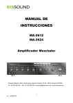
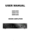
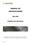
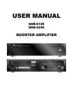
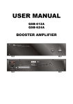
USER MANUAL
QSM-624ET
MIXER AMPLIFIER
Version 2 - 9 January 2008
Page 1 of 10
© Prime Audio - PO Box 353, Kerrimuir VIC 3129, Australia - Ph.03 9383 1399 – www.primeaudio.com.au
QSM-624ET AMP 240W 3 TONE CONTROL + CHIME
Mixer Amplifier
FRONT PANEL
1.
Channel 1
Volume Control
2.
Channel 2
Volume Control
3.
Channel 3
Volume Control
4.
Channel 4
Volume Control
5.
Channel 5
Volume Control
6.
Master Tone Control (Bass)
7.
Master Tone Control (Treble)
8.
Master Volume Control
9.
Power On / Off switch
10.
Power On / Off indicator LED
11.
Output Level indicator LED
12.
Chime Emergency Push Switches
Version 2 - 9 January 2008
Page 2 of 10
© Prime Audio - PO Box 353, Kerrimuir VIC 3129, Australia - Ph.03 9383 1399 – www.primeaudio.com.au
REAR PANEL
1. Mains Input Socket
13. MIC 4 Input (XLR Jack)
2.Power Fuse
14. MIC 3/TEL Selector Switch
3. Earth Connection Screw
15. MIC 3 Input (XLR Jack)
4. DC Power Supply Terminals
16. MIC 2 Input (XLR Jack)
5. Speaker Output Terminals
17. MIC 1 Input (XLR Jack)
6. Aux Output (RCA Jack)
18. Mains Voltage (115V/230V) Selector Switch
7. Tape Output (RCA Jack)
19. Chime Emergency Control Terminals
8. Aux 3 Input (RCA Jack)
20. Aux 2 Input (RCA Jack)
9. Aux 3 Level Control
21. Aux 1 Input (RCA Jack)
10. MIC 5/Aux 2 Selector Switch
22. Tel Page Input (Screw Terminals)
11. MIC 5 Input (XLR Jack)
23.Chime (Ding Dong) Control Terminals
12. MIC 4/Aux 1 Selector Switch
24. Chime (Ding Dong) Control on/off Switch
Mains Connection
The supply transformer has been designed for use on either 115Vac or 230Vac, selected by slide
switch on rear panel. The amplifier is factory set at 230Vac mains voltage.
Battery Connection (24Vdc)
When using external batteries, earth the amplifier via the screw terminal because of the high
voltages present. Electrical stability of the system is increased by earthing the case.
Version 2 - 9 January 2008
Page 3 of 10
© Prime Audio - PO Box 353, Kerrimuir VIC 3129, Australia - Ph.03 9383 1399 – www.primeaudio.com.au
NOTE: the connection cable must be fitted with an in-line fuse.
Quick blow type F15A when
Connecting batteries please ensure correct polarity.
Microphone Connection
Mic1-5 inputs are balanced standard 3-PIN XLR on the rear panel (with selectable phantom power on MIC 1-2-3).
XLR (Balanced Operation)
Pin 1:
Screen
Pin 2:
Signal (live)
Pin 3:
Signal (return)
Version 2 - 9 January 2008
Page 4 of 10
© Prime Audio - PO Box 353, Kerrimuir VIC 3129, Australia - Ph.03 9383 1399 – www.primeaudio.com.au
WARNING
This symbol is intended to alert the user to the presence of
un-insulated “dangerous voltage” within the products
enclosure that may be of sufficient magnitude to constitute
a risk of electric shock to persons
This symbol is intended to alert the user to the presence of
important operation and maintenance (servicing)
instructions in the literature accompanying the appliance.
CAUTION:
TO REDUCE THE RISK OF ELECTRIC SHOCK.
DO NOT REMOVE COVER (OR BACK).
NO USER-SERVICEABLE PARTS INSIDE.
Caution:
To prevent electric shock do not use this (polarized) plug
with an extension cord, receptacle or other outlet unless
the blades can be fully inserted to prevent blade exposure.
REFER SERVICING TO QUALIFIED SERVICE PERSONNEL.
WARNING
To prevent fire or shock hazard, do not expose
the unit to rain or moisture.
*Do not install this equipment in a confined space such as a bookcase or similar unit.
*The apparatus shall not be exposed to dripping or splashing and no objects filled with liquids, such as vases, shall be placed on the
apparatus.
*Worded: “WARNING FOR YOUR PROTECTION PLEASE READ THE FOLLOWING WATER AND MOISTURE:Unit should not be
used near water (eg. near a bathtub, washbowl, kitchen sink, laundry tub, in a wet basement, or near a swimming pool, etc.).
should be taken so that objects do not fall and liquids are not spilled into the enclosure through openings.”
Version 2 - 9 January 2008
Page 5 of 10
© Prime Audio - PO Box 353, Kerrimuir VIC 3129, Australia - Ph.03 9383 1399 – www.primeaudio.com.au
Care
Installation
Unpacking
Although your QSM-624ET is neither complicated nor difficult to operate, we recommend you take a few
minutes to read this brief manual and familiarize yourself with the important information regarding product
features, setup and operation.
Environment
Never place this product in an environment which could alter its performance or reduce its service life.
Such environments usually include high levels of heat, dust, moisture and vibration.
Important Safety Instructions
1.
Read these instructions.
2.
Keep these instructions.
3.
Heed all warnings.
4.
Follow all instructions.
5.
Do not use this apparatus near water.
6.
Clean only with a dry cloth.
7.
Do not block any ventilation openings.
8.
Do not install near any heat sources such as radiators, heat registers, stoves, or other apparatus
Install in accordance with the manufacturer’s instructions.
(including amplifiers) that produce heat.
9.
Do not defeat the safety purpose of the polarized or grounding type plug.
blades with one wider than the other.
prong.
A polarized plug has two
A grounding type plus has two blades and a third grounding
The wide blade or the third prong is provided for your safety.
If the provided plug does not
fit into your outlet, consult an electrician for replacement of the obsolete outlet.
10.
Protect the power cord from being walked on or pinched particularly at plugs, convenience
receptacles and the point where they exit from the apparatus.
11.
Only use attachments/accessories specified by the manufacturer.
12.
Use only with the cart, stand, tripod, bracket or table specified by the manufacturer or sold with the
apparatus.
When a cart is used, use caution when moving the cart/apparatus combination to avoid
injury from tip-over.
13.
Unplug this apparatus during lightning storms or when unused for long periods of time.
14.
Refer all servicing to qualified service personnel.
Servicing is required when the apparatus has
been damaged in any way, such as the power supply or plug is damaged, liquid has been spilled or
objects have fallen into the apparatus, the apparatus has been exposed to rain or moisture, does not
operate normally, or has been dropped.
Version 2 - 9 January 2008
Page 6 of 10
© Prime Audio - PO Box 353, Kerrimuir VIC 3129, Australia - Ph.03 9383 1399 – www.primeaudio.com.au
General Installation
DO NOT
run microphone cables near mains, data, telephone or 100V line cables.
DO NOT
run 100V line cable near data, telephone or other low voltage cables.
DO NOT
exceed 90% of the amplifiers output power when using 100V line (speech
only).
DO NOT
exceed 70% of the amplifiers output power when using 100V line (high
level background music).
DO NOT
use re-entrant horn loudspeakers for background music unless the loudspeaker has been
specifically designed for this purpose.
AVOID
jointing the microphone cable, when this is unavoidable make sure a good screened connector is
used.
ALWAYS
use a unbalanced or floating low impedance microphone terminating into a unbalanced input on
long microphone cable runs.
ALWAYS
use a mains grade double insulated cable for the loudspeaker cable runs.
ENSURE
that all loudspeakers are in-phase.
ENSURE
that there are no short circuits on the loudspeaker line before connecting to the amplifier.
Front Panel Control
1.
Power Switch – for normal use this control should be on.
It is suggested that the power switch be turned off for
weekends or holiday breaks.
2.
Channel Volume Controls Nos 1-5 – these level controls provide volume adjustment out over the speakers of the
various input services that may be connected to the Amplifier.
These may be microphone, cassette, CD etc.
3.
Treble Control – adjusts higher frequency response of the amplifier.
4.
Bass Control – adjusts the lower frequency response of the amplifier.
5.
Chime – “Pre-announcement” chime to call attention that an announcement is about to be made. This function
These controls are usually set midway.
may be set to operate automatically when connected to a suitable microphone via connections on the rear panel.
6.
Bell Switch – pressing this button will generate an electronic bell sound for as long as the button is depressed.
The feature may be activated by time clock or other means via the rear panel terminals.
The primary function of
the bell is to signify starts or ends of particular periods of time eg. lunch breaks, school classroom periods etc.
7.
Alert Switch – the alert switch generates an emergency alert electrical tone.
This tone is to Australian Standard.
Its purpose is to call attention to a possible emergency and for those in the building or area to cease activities and
remain quietly for further instructions.
8.
Evacuation Switch (EVAC) – this switch will general an electronic emergency evacuation tone to Australian
Standard.
This tone is used to call attention for the immediate and orderly evacuation of the building to a
pre-determined evacuation plan.
9.
Green – Red L E D – this row of lights starting from left to right, green to red shows at what level the amplifier is
operating.
red.
The normal operation levels for any source should be in the green areas, with the occasional peak into
Continuous operation in the red will overdrive the amplifier and may cause damage and distortion of sound.
Version 2 - 9 January 2008
Page 7 of 10
© Prime Audio - PO Box 353, Kerrimuir VIC 3129, Australia - Ph.03 9383 1399 – www.primeaudio.com.au
QSM-624ET Technical Specifications
Type
Chime Mixer Amplifier
Model
QSM-624ET
Supply
Mains Voltage
AC 115V/ 230V, 50 / 60Hz ± 10% Switchable
Battery Voltage DC 24V (MAX 10% deviation)
Output power
Max:
360W
Rated:
240W
Output
Speaker outputs:
Music/speech: , 8Ω, 70V, 100V
Chime :1/8 power output
Tape output: 1V 15KΩ
Aux output: 1V, 150Ω
Inputs
Mic 1~5: sensitivity. Adjustable (1mV), 600Ω balanced.
Aux 4~6: 150mV, stereo 22K,
TEL:
Frequency response
150mV, Adjustable 600Ω, balanced
Mic 1~Mic 5: 60Hz ~ 15KHz ± 3dB
Aux 4~ 6: 50Hz ~ 20KHz ± 3dB
TEL: 50Hz ~ 15KHz ± 3Db(cmrr)
Total harmonic distortion
Less than 1% at 1KHz, rated power
Signal to noise ratio
All Volume Controls C.C.W.:
Mic 1~ 5:
Tone Controls
60dB below rated power
TEL:
80dB rated power
Aux:
80dB below rated power
Bass:
± 10dB at 100Hz
Treble:
Controls
80dB below rated power
± 10dB at 10KHz
Front Panel
Power switch
Chime Emergency push switch
Channel 1~5 volume control
Tone controls (Bass, Treble)
Master volume control
Rear Panel:
Aux 3 volume control
Mic 3/Tel Slide switch
Mic 4/Aux 1 Slide switch
Mic 5/Aux 2 Slide switch
Version 2 - 9 January 2008
Page 8 of 10
© Prime Audio - PO Box 353, Kerrimuir VIC 3129, Australia - Ph.03 9383 1399 – www.primeaudio.com.au
Chime Emergency controls
Chime DING DONG control
Chime DING DONG Slide switch
AC 115V / 230V voltage Selector switch
Power indicator (LED), output level indicators (6 LEDS)
AC power consumption
640W
DC power consumption
15A
Phantom power
Set up Mic 1 “on”, Mic 2 “on”, Mic 3 “on”, Mic 4 “off”, Mic 5 “off”
Phantom power output 16V as set up “on”
Priority
Chime can mute all channel
Priority level ( Mic 1: 0.3mv)
Channel 1 can mute Channel3 ~5, Aux3
Dimensions ( H x W x
88(H)x425(W)x305(D)
D )mm
Weight
11.8 kgs
Color
Black
Mounting options
Table top or 19” rack mountable
Version 2 - 9 January 2008
Page 9 of 10
© Prime Audio - PO Box 353, Kerrimuir VIC 3129, Australia - Ph.03 9383 1399 – www.primeaudio.com.au
Trouble Shooting Guide
No Sound
Check Amplifier is plugged into power source and power switch illuminates when on.
If the power point is tested OK with another appliance and the amplifier does not
illuminate when turned on refer to qualified service personnel.
If the amplifier has power, press the “bell” button to see if there is visual indication of
sound on the V.U. Meter.
If there is no indication of sound refer to qualified service
personnel.
Test other input sources for indication of sound on the V.U. Meter.
volume controls are turned on.
Check the relevant
If there is no indication of sound from any source,
refer to qualified service personnel.
If there is no indication of sound from any one source the problem is more than likely in
that source.
If the amplifier shows visual indication of sound ie. the amplifier is not working but still
no sound out over the installation, the problem may be external to the amplifier and
should be referred to qualified service personnel.
Squealing
When microphone talk button is depressed.
This is caused by the microphone being
too close to the loudspeaker.
Distortion
Or insufficient level of sound from any one source.
Adjust relevant volume control for that particular source.
NOTE
There are no user controls, adjustments, or serviceable items inside the amplifier
case.
Fuses on the rear panel should be replaced by qualified service
personnel after investigation of the cause of the fuse failure.
Version 2 - 9 January 2008
Page 10 of 10
© Prime Audio - PO Box 353, Kerrimuir VIC 3129, Australia - Ph.03 9383 1399 – www.primeaudio.com.au