
1
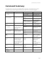
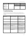
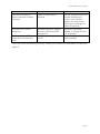
www.jva-fence.com.au JVA SMS Gateway User Manual PTE0319 JVA SMS Gateway User Manual Introduction The PTE0319 JVA SMS Gateway enables a group of JVA Z Series energisers to be controlled and monitored by SMS from anywhere in the world. With a phone call or short SMS, users can obtain an up-to-date status report of all their energisers, turn on (arm) or off (disarm) all the energisers at once, as well as switch handy output relays for custom applications. This unit can store up to 9 phone numbers. If an energiser goes into alarm, or one of two inputs are triggered, an SMS will be automatically generated and sent to each stored number. Designed with ease of use in mind, the system does not have an endless list of configuration options or complex methods of set-up. All configuration is via SMS to the unit, secured with a user definable PIN. The JVA SMS Gateway communicates on the widely supported and robust GSM mobile phone network, and will work in any country with 2G coverage. Simply insert a valid topped-up SIM card from your preferred carrier and you are ready to remotely control and monitor your energisers, from anywhere in the world. Features Works with entire JVA Z range of energisers, as well as the ZM1 and ZM20 monitors Can monitor and control up to 15 devices (linked via Keypad bus) , as well as two dry contact inputs and two 30Vdc 8A relays Produces an up-to-date status report including arm state, alarms and primary voltages of each device, and input and output states Responds to status request by SMS or missed call Can store up to 9 phone numbers to be notified if a device goes into alarm, or one of two inputs are triggered All commands secured by user configurable PIN Easily configurable by SMS Compatible with the all types of JVA Keypad and with Perimeter Patrol Page 1 JVA SMS Gateway User Manual Specifications Power supply Inputs Outputs SIM Antenna connector 12 V DC 1A Dry contact or active pull-down 30Vdc 8A SPDT Micro Female SMA Overview Page 2 JVA SMS Gateway User Manual LED Indicators GSM STATUS POLL FIRE On (no flash): If there is a problem with the antenna or SIM card, the LED will remain on, indicating the unit is not connected to the GSM network Slow flash: GSM network connected Very fast flash: The unit has corrupted software Blinks when the unit receives a status message from the group Blink when the unit is sending a command to the group or requesting additional information Not used. Inputs Two dry contact inputs are provided. If the unit sees a short circuit between the input terminals it will register the input as being ‘On’. Just like the inputs on all JVA Z series devices, the input can also be asserted from an electrical source by driving the right-most terminal to ground. Outputs Two SPDT relays are available as general purpose outputs. These relays can switch DC voltage up to 30V and 8A. The outputs can be switched on or off by SMS, and are ideal for connection to external lights, pumps, electric motors, gate openers, or interfacing to an existing alarm or control system. Antenna A GSM antenna is supplied with the unit and must be connected to the unit for it to communicate on the mobile network. If mobile reception in the area is particularly weak, the antenna can be substituted for a more powerful one, provided it has a male SMA connector. Ensure the antenna is mounted away from any high voltage cables or AC power cables which could cause interference. If the unit is mounted inside a metal enclosure, the antenna should be mounted external to the enclosure and the cable entry hole be sealed against water ingress. Page 3 JVA SMS Gateway User Manual Power and Keypad Bus The keypad bus enables digital communication between the SMS Gateway and connected devices. Connect the DATA and GND terminals to the equivalent terminals of all connected devices. The SMS Gateway requires 12V dc to operate. This power may be supplied from the keypad bus of a connected energiser, or for best results a separate 12V 1A power supply may be used. Do not connect the unit to a separate power supply and keypad bus +12V of an energiser at the same time. The SMS Gateway operates as a keypad with keypad ID 2. Keypad ID 3 is reserved. If other keypads or keypad devices such as the PAE212 or Perimeter Patrol are to be used with the group, they should be set to keypad ID 1, 4, or greater. SIM card The SMS Gateway requires a Micro SIM card that is activated and has credit. The SIM card should first be tested in a phone to ensure it can send and receive text messages, and also receive phone calls. Insert the sim card with the cut corner to the bottom right, unclipping the PCB from the enclosure temporarily if required. Connect the antenna and power and confirm the green ‘GSM’ LED flashes every 2 seconds. If the LED stays on (without flashing) the unit cannot connect to the network, indicating a problem with the SIM card or antenna. A good value pre- or post-paid plan should be chosen for the SIM card. The unit does not use data or voice calls, only SMSes. Estimate how many SMSes are likely to be generated per day. If the unit is queried for status often, a plan offering unlimited SMSes may be good value, keeping in mind the ongoing cost will mostly likely be monthly. If the unit is unlikely to generate a SMS in normal operation and is only for emergencies, plans offering more expensive SMSes but longer credit expiry periods are also available. Page 4 JVA SMS Gateway User Manual Installation Detach the front of the case by gently lifting the side clips. Unclip the top of the circuit board to remove from the case back. Mount the case back using suitable screws. Be sure the screw head will not contact the PCB when it is re-installed. The unit must be mounted indoors or in a suitable enclosure to protect it from moisture. It is NOT water proof and damage due to moisture is not covered by the warranty. Obtain a suitable SIM card. Activate it according to the instructions, either via the internet or by phone, and make sure it has credit available. Insert the SIM card into a mobile phone and confirm you can receive calls and send SMSes. Remove the SIM card from the phone and insert into the unit, contact side down with the notched corner to the lower right. Clip the circuit board into the case back. Connect the antenna. Mount the antenna away from high voltage and mains power cables, vertically if possible. If the unit is housed in a metal enclosure, the antenna should be mounted outside the enclosure and the enclosure earthed. Connect +12V, Data and Ground wires from the unit to a JVA energiser. Power on the energiser. The unit should also power on. Confirm the GSM light flashes briefly once every 2 seconds, and that the STATUS light flashes approximately every second. Clip the case front back on. Your JVA SMS Gateway is ready to use. Operation SMS Commands The unit is controlled and configured by SMS. All commands are of the format PIN command parameter with spaces separating each part. The commands and parameters are not case sensitive. Many commands may be replaced with only their first letter. A help message can be requested by issuing the help command. The unit will reply with a summarised list of available commands. PIN All commands are prefixed by a PIN number, to secure the unit against unauthorised changes. The PIN must be between 4 and 12 digits long. The default PIN is 1234. The Page 5 JVA SMS Gateway User Manual PIN can be changed by issuing a changepin command, with the new PIN as the parameter. If successful the unit will reply and inform everyone on the report list of the new PIN. If you forget the PIN, a factory reset must be performed. See the section ‘Factory Reset’ for more information. Querying the Status The SMS Gateway can be queried to return the status of the inputs, outputs and all Z series devices connected to it via the Keypad Bus. Simply issue a status command, or alternatively call the unit. It will detect your call and hang up after two rings, then SMS you with a complete status. For this to function it is important your Caller ID information is not blocked, otherwise the unit will not know which number to send the reply to. The SMS will take the format: Model(ID) <On (V1, V2) or Off> <Alarms> Model(ID) <On (V1, V2) or Off> <Alarms> … In1:<on|off> In2:<on|off> Out1:<on|off> Out2:<on|off> Model ID V1, V2 Alarms Energiser model eg Z14, ZM20 Keypad bus device ID (1-15) Primary voltages, usually feed and return, in kV CommsFail OR FenceAlarm1 FenceAlarm2 AcFail LowBatt BadBatt Tamper Fault GateAlarm OR No Alarms The hardware status of the unit can also be requested by issuing a gsm command. The unit will reply with signal strength, the last system start date and time as stored in memory, and the firmware version. Report List The unit can store up to 9 phone number which it will SMS if a device goes into alarm, or an input changes. This list is configured and maintained using the add and remove commands. You can retrieve the current list of numbers using the numbers command. Issuing an add command, followed by a valid number, will add the number to the report list. It is possible to add duplicate numbers to the list, which will result in that number receiving multiple SMSes each time an SMS is broadcast. Numbers can be in either the Page 6 JVA SMS Gateway User Manual national format, eg 0412 345 6789, or international dialling format, eg +61 412 345 6789. After successfully adding a number the unit will reply with the report list, and an SMS will be sent to the new number informing them they were added. Numbers can be removed by issuing the remove command, followed either by the number, or the position of the number in the report list. If entering a number, it must be in the same format as it is stored in the list. After successfully removing a number the unit will reply with the report list, and an SMS will be sent to the removed number informing them they were removed. Controlling Energisers and Outputs The unit can turn all energisers on (arm) or off (disarm) by issuing the on or off command. When arming, the unit will arm in high power only, and arm both channels of any dual channel energisers. When the unit has confirmed the new arm state it will reply to the sender with a confirmation message. The unit has two relays than can be turned on or off. Issue an output1 or output2 command with the parameter on or off. Note there is no space between “output” and the number “1” or “2”. The unit will reply with a confirmation message. Alerting users of alarms The unit monitors the connected energisers and will send a SMS to everyone on the report list if the following things occur: A fence alarm occurs, usually due to a short on the fence An energiser stops communicating An input changes If multiple energisers report changes at the same time, the unit will send one SMS for each change. Page 7 JVA SMS Gateway User Manual Basic Commands The following is the minimum commands you will need to know to get your JVA SMS Gateway working. It assumes the PIN is still set to the default of 1234. When you have installed and powered on your unit for the first time, the connected energiser(s) are powered on, and the GSM light is flashing once every 2 seconds, issue a status command 1234 s The unit will reply with a summary of all connected energisers. Next, add your number to the report list. For example if your phone number was 0412 345 6789, send 1234 a 04123456789 The unit will reply with “1.04123456789” indicating there is one number on the report list – yours. Now try arming you energiser(s) by sending 1234 on You should see the energiser(s) arm, and receive an sms saying “Energiser(s) are on”. Now disarm the energiser(s) by sending 1234 off You will see the energiser(s) disarm and receive another confirmation text. For a complete list of commands, refer to the section “Command Summary”. Page 8 JVA SMS Gateway User Manual Command Summary The table below summarises all available SMS commands. The default PIN is used in examples but you should replace this with your own PIN if it has been changed. Command changepin <PIN> or c <PIN> add <number> or a <number> numbers or n remove <index> or r <index> remove <number> or r <number> Description Changes the PIN Example 1234 changepin 4321 4321 c 1234 1234 c 123 Adds the specified 1234 add 041 234 number to the report 5678 list 1234 a +61 41 234 5678 1234 a 555JVAROCKS Requests the report list Removes the number at the given index from the report list Removes the specified number from the report list gsm or g Requests GSM status status or s or? Requests energiser/monitor primary voltages, arm and alarm state, and unit input and output state Requests a command summary help or h on or arm off or disarm 1234 numbers 1234 n 1234 remove 1 1234 r 2 1234 remove 041 234 5678 1234 r +61 41 234 5678 1234 gsm 1234 status 1234 s 1234 ? Arms all devices 1234 help 1234 h 1234 1234 on Disarms all devices 1234 off Response PIN is now 4321 PIN is now 1234 Invalid PIN 1.0412345678 1.0412345678 2.+61412345678 Invalid phone number 1.0412345678 2.+61412345678 1.+61412345678 Number not found in report list Number not found in report list Report list is empty Signal: 25 System up: 13:56 2015-0610 Fw: 1v3.0 Z14(1) On (6.8kV, 6.4kV) No alarms ZM20(2) Off LowBatt In1 Off In2 Off Out1 On Out2 Off This table, in 160 characters Energiser(s) are on Energiser(s) are off Page 9 JVA SMS Gateway User Manual Command output1 <on|off> or out1 <on|off> or 1 <on|off> or aux <on|off> output2<on|off> or out2 <on|off> or 2 <on|off> or gate <on|off> Description Controls relay 1 or 2 Example 1234 output1 on 1234 1 off 1234 out2 on 1234 gate off Response Output 1 is now on Output 1 is now off Output 2 is now on Output 2 is now off Troubleshooting The JVA SMS Gateway is designed to work straight out of the box with little set up or configuration. The only crucial step is to ensure the unit has good mobile reception and an activated SIM card with credit. Refer to the troubleshooting table below for more information. Fault No lights are on Likely Cause Power is not connected Power wires are reversed GSM light is on, not flashing SIM card not activated Poor signal strength GSM light flashes fast and continuously Status light not flashing Software corruption Keypad bus is not connected Energiser malfunction Group configured incorrectly Remedy Check power connections Check voltage at power connections with a multimeter Confirm SIM is activated by inserting into a mobile phone and sending and receiving texts Check antenna connection Move antenna mounting place Contact your nearest JVA distributor Check the keypad bus DATA and GND connections Confirm a JVA keypad can control the energiser using the same connections If there is more than one energiser, ensure one is configured as master (device ID 1) and the others have unique device IDs of 2 or more Page 10 JVA SMS Gateway User Manual Fault Unit does not reply to phone calls with a status message Likely Cause Caller ID information blocked Unit does not control energisers Another keypad or keypad device is connected with keypad ID 2 Insufficient or expired credit Unit responds to SMS commands but does not reply Remedy Use the same phone to call another number and confirm your number appears on their phone. Check phone settings for ‘Caller ID blocking’ Disconnect the other keypad, or change its ID to 1, 4, or greater Check the SIM card has credit available If the unit is still not working correctly, contact your nearest JVA distributor for technical support. Page 11 JVA SMS Gateway User Manual Support Factory Reset If the PIN has been changed from its default setting and has been forgotten, the unit will need to be factory reset. Confirm the unit has signal and the SIM card has credit by issuing the command ‘1234 g’ and awaiting the reply “Incorrect PIN”. Contact your nearest JVA distributor with the mobile phone number of the SIM card and they will remotely reset the unit for you. JVA Distributors If you have any questions or need further assistance, please email us at [email protected] or phone one of the numbers listed below Region Australia South Africa World Wide Number 07 3103 0582 0861 782 349 +61 7 3103 0582 For more information on our complete range of electric fencing products please see the JVA website www.jva-fence.com.au Page 12 © JVA 2015. Manufactured for JVA by Pakton Technologies The JVA logo is a trademark of JVA Technologies Pty Ltd


![Haemophilus influenzae Agglutinating Sera [FR]](http://vs1.manualzilla.com/store/data/006448070_1-234c3bd889eba75383fe82bfe7f6d431-150x150.png)