1
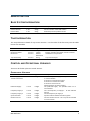
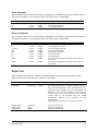
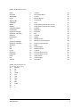
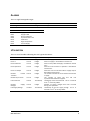
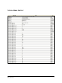
i-STS
SNMP MIB
User Manual
Version 2.3.1
CONTENTS
Contents
1
Introduction
2
Conventions
2
MIB Definition
3
Basic System Information
3
Trap Information
3
Control and Operational Variables
3
Operational Variables
3
Input Variables
4
Output Variables
4
Event Log
4
Alarms
6
Utilisation
6
Typical Walk Output
7
Contents
1
INTRODUCTION
This MIB documentation aims to provide all necessary definitions to provide basic control and
monitoring capabilities of the Static Transfer Switch via SNMP version 1.0.
There are three sections to the MIB:
1.
Basic System Information
2.
Trap Information
3.
Control and Operational Variables
CONVENTIONS
The i-STS Manufacturing Private Enterprise Number is 32796. Therefore, the prefix for all OIDs is:
43.6.1.4.1.32796
For all table variables, 0 is the first index, and is referenced by adding an ‘[index]’ to the end of the
OID. ie, for the trap receiver IP:
43.6.1.4.1.32796.2.1.1.3.0
Some variables may be represented as a base 10 multiple of the actual value, so as to avoid floating
point values. The multiplier will be indicated where appropriate.
Note also that all variables are read only unless otherwise specified.
Introduction
2
MIB DEFINITION
BASIC SYSTEM INFORMATION
Variable
Product Name
Product Version
Product Date
OID
1.1.0
1.2.0
1.3.0
Type
String
String
String
Description
Name and variant of the Static Switch
Version number of the Static Switch
Date stamp for the product version
TRAP INFORMATION
The Trap table stores details for up to two receivers. 0 is the index of the first entry into the table.
Entries are writeable.
Variable
Trap Receiver Id
Receiver Enabled
Receiver IP
OID
2.1.1.1.0
2.1.1.2.0
2.1.1.3.0
Trap Community
2.1.1.4.0
Type
Integer
Integer
Dotted
Notation IP
String
Description
Index into the Trap Table
Boolean indicator of whether receiver enabled
IP Address of Trap receiver
Trap Community Id
CONTROL AND OPERATIONAL VARIABLES
These can be further split into several sections
OPERATIONAL VARIABLES
Variable
Active Supply/
Transfer Command
OID
3.1.1.0
Type
Integer
Preferred Supply
3.1.2.0
Integer
Frequency Supply 1
3.1.3.0
Integer
Frequency Supply 2
Synchronisation
Neutral Current
3.1.4.0
3.1.5.0
3.1.6.0
Integer
Integer
Integer
MIB Definition
Description
The currently active supply. The possible values 1
or 2 are writeable.
A Value of 3 activates the inhibit
A Value of 4 releases the inhibit
A Value of 5 Alarm Cancel
(Reset & Release all other Inhibits)
The preferred supply. The possible values 1 or 2
are writeable.
10 x the frequency of supply 1. Ie 501 indicates
50.1 Hz.
10 x the frequency of supply 2.
Synchronisation between the two supplies
10 x the Neutral current. This may not be available
on some models.
3
INPUT VARIABLES
This is a table of either one or three entries, depending on the model of the Static Transfer Switch. It
represents the phases. 0 is the index of either the main entries, or Red phase.
Variable
Input Variables
S1
S2
OID
3.2.1.0
3.2.2.0
3.2.3.0
Type
Integer
Integer
Integer
Description
The index into the Input Variables table
The voltage of Supply 1
The voltage of Supply 2
OUTPUT VARIABLES
This is a table of either one or three entries, depending on the model of the Static Transfer Switch. It
represents the phases. 0 is the index of either the main entries, or Red phase.
Variable
Output Variables
S3
Current
kVA
kW
PF
CF
THDI
OID
3.3.1.0
3.3.2.0
3.3.3.0
3.3.4.0
3.3.5.0
3.3.6.0
3.3.7.0
3.3.8.0
Type
Integer
Integer
Integer
Integer
Integer
Integer
Integer
Integer
THDV
3.3.9.0
Integer
Description
The index into the Output Variables table
The voltage of the output
10 x the current delivered
10 x the calculated kVA
10 x the calculated kW
10 x Power Factor
10 x Crest Factor
10 x the percentage of Total Harmonic Distortion of
the current
10 x the percentage of Total Harmonic Distortion of
the Voltage.
EVENT LOG
This is a table of event entries. There is a variable amount of entries up to a maximum of 100.
When receiving next index of 0xFF, it indicates end of table.
Variable
Event Log
Event Item
OID
3.4.1.0-100
3.4.2.0-100
EVENT_TIME
EVENT_NUM
EVENT_VAL
Timestamp
Integer
Integer
MIB Definition
Type
Integer
Integer
Description
The index into the Event Log
The value returned also is now the number of seconds
since 1 Jan 1970 00:00:00. This is the well-known Unix
timestamp that practically all 32 bit timestamps are
based off. There are many software libraries that can
convert that to text of any format, so the returned
number needs to be formatted using your SNMP
Management Software. As an example, see the
following URL:
http://www.onlineconversion.com/unix_time.htm
43.6.1.4.1.32796.3.4.2
43.6.1.4.1.32796.3.4.3
43.6.1.4.1.32796.3.4.4
4
EVENT_NUM can be one of:
Boot
Initialise
Watchdog
Stack
Blank Index
EEPROM
ROM
Battery
Communications
Calibration
Supply 1 Average
Supply 1 Transient
Supply 1
Frequency
Sync
Supply 2 Average
Supply 2 Transient
Supply 2
On
Off
Force
Supply 3
Overload
Load
Fail
Transfer
0
1
2
3
4
5
6
7
8
9
10
11
12
13
14
15
16
17
18
19
20
21
22
23
24
25
Transfer
Low Power Mode
Current
Manual Bypass
Preference
Varf
Total Harmonic Distortion Current
Total Harmonic Distortion Voltage
Ambient
Magnetics
Heat-sink
Fan
Thermal
Debug
Remote Power
Remote Transfer Request
Local Transfer Request
Blank
Breaker Open
Breaker Closed
Tripped
Thyristor Short circuit
Thyristor Open circuit
Alarm Cancel
Power Supply
Back Feed
25
26
27
28
29
30
31
32
33
34
35
36
37
38
39
40
41
42
43
44
45
46
47
48
49
50
EVENT_VAL can be one of:
0, 1, 2, 3, 4, 5, 6, 7, 8, 9
10
Nothing
11
OK
12
HI
13
LOW
14
FLT
15
CLR
16
LOS
17
ON
18
OFF
19
TMR
20
1
21
2
MIB Definition
5
ALARMS
This is a single bitmapped integer.
Variable
Event Log
Bit Id
0x01
0x02
0x04
0x08
0x10
0x20
0x40
OID
3.5.1.0
Type
Integer
Description
Bitmapped alarm
Alarm
Supply 1 Bad
Supply 2 Bad
Not on Preferred
Synchronisation Loss
Load Fault
High Temperature
Forced Supply
UTILISATION
This is a set of variables indicating the unit’s general statistics.
Variable
Hours 1
Hours 2
Hours Preferred
OID
3.6.1.0
3.6.2.0
3.6.3.0
Type
Integer
Integer
Integer
Hours Operation
3.6.4.0
Integer
Hours no Output
3.6.5.0
Integer
Number
Forced
Transfers
Number Sync Losses
3.6.6.0
Integer
3.6.7.0
Integer
Last Load Fault
3.6.8.0
Time Stamp
Number
Supply
Outages
Last Supply Outage
3.6.9.0
Integer
3.6.10.0
Time Stamp
MIB Definition
Description
Hours on supply 1. Rounded to nearest hour.
Hours on supply 2. Rounded to nearest hour.
Hours on the preferred supply. Rounded to nearest
hour.
Hours the unit has been in operation. Rounded to
nearest hour.
Hours the unit has not been able to supply output.
Rounded to nearest hour.
The number of times the unit has been forced onto
a supply.
The number of times the unit has lost
synchronisation between supplies.
Timestamp of the last load fault. This is in seconds
st
since 1 of January 2002?
Number of supply outages that have occurred
during units operation.
Timestamp of the last supply outage. This is in
st
seconds since 1 of January 2002?
6
TYPICAL WALK OUTPUT
MIB Definition
7
i-STS
Manufacturing is a subsidiary of
STATIC POWER PTY. LTD.
ABN 42 101 765 913
Post to:
Box 2003
Research Delivery Centre
Research VIC 3095
Australia
Manufactured at:
5 Candlebark Court
Research VIC 3095
Australia
Phone:
Fax :
Email :
Web :
+613 9437 0494
+613 9437 0939
[email protected]
www.i-sts.com.au
Copyright © 2014 STATIC POWER PTY. LTD.
This user manual is protected under international copyright laws. No part of this user manual may be
reproduced, distributed, translated, or transmitted in any form or by any means, electronic or
mechanical, including photocopying, recording, or storing in any information storage and retrieval
system, without the prior written permission of STATIC POWER PTY. LTD
8