1
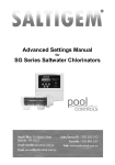
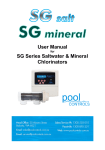
User Manual for the Gemini System 2013-14 Contents Manufacturers’ Warranty Introducing the Gemini Combo System How it Works Initial Pool Balance Pool Chemical Dilutions Installation Guide Gemini Control Front Panel Gemini Salt Front Panel Navigating the Gemini Control Menu System Timer Menu ORP (Chlorine Output) Menu pH Menu Status Indicator, Warnings and Safety Shutdowns Maintenance Troubleshooting 2 4 5 6 7 8 11 13 14 15 16 17 19 22 24 IMPORTANT If the power cord is damaged the unit must be returned to Pool Controls for repair. Always read the instructions and warnings on chemical containers before using chemicals. Serial Number........................................ Date of Installation................................ Installed by............................................. Page 1 Manufacturer’s Warranty Pool Controls products come with guarantees that cannot be excluded under the Australian Consumer Law. You are entitled to a replacement or refund for a major failure and for compensation for any other loss or damage. You are also entitled to have the goods repaired or replaced if the goods fail to be of acceptable quality and the failure does not amount to a major failure. The benefits under this warranty are in addition to other rights and remedies under a law in relation to the goods. Pool Controls warrants all components of Gemini Combo System to be free from defects in material and/or workmanship for a period of 2 years from the original date of purchase or installation. Additional Pro-rata Warranty on Multi-electrodes and Cells Pool Controls warrants the following components to be free from defects in material and/or workmanship for a period of 2 years, followed by 36 months pro-rata warranty: Gemini Control Multi-electrode (Probe) Gemini Salt Electrode (Cell) Exclusion for Wearing Parts This warranty does not extend to wearing parts, in particular the squeeze tubes fitted in peristaltic dosing pumps. Squeeze tubes should be replaced every six months by a suitably qualified technician. Pool Controls is not liable for any failure of its products or other damage caused by failure of a squeeze tube that has been used for more than six months. WARRANTY OBLIGATIONS OF POOL CONTROLS If a defect in workmanship or materials in any Pool Controls product covered by this warranty is discovered during the term of the warranty, and provided the warranty holder follows the procedure set out below, Pool Controls will, at its option, repair or replace that item. PROCEDURE FOR CLAIMING UNDER THIS WARRANTY In order to claim under this warranty, the warranty holder must: Contact Pool Controls Service as soon as possible after the discovery of the defect and in any event, within the relevant warranty period; Provide proof of purchase and confirm date of installation; Confirm that the installation was completed by a suitably qualified technician, as set out in the installation manual; and Page 2 If required, arrange for the relevant Pool Controls’ product to be returned to Pool Controls for repair, and the warranty holder is responsible for the cost and risk of any freight or transportation to and from Pool Controls. CALL OUT FEES This is a “Back to Base” Warranty, which means that if the Pool Controls product needs to be serviced, replaced or repaired at a place other than Pool Controls’ premises, a call out fee will be charged to cover the cost of travel by an authorised Pool Controls technician. Please note that this call out fee will NOT be charged when the relevant Pool Controls product is returned to Pool Controls for repair. If an authorised Pool Controls technician repairs or replaces a Pool Controls Product and this warranty does NOT apply, a fee for labour and parts supplied will be charged in addition to the call out fee. If the Pool Controls product needs to be returned for repairs under this warranty, the warranty holder is responsible for the cost and risk of any freight or transportation to and from Pool Controls. WARRANTY EXCLUSIONS This warranty extends to the original owner only, beginning on the date of installation and is not enforceable by any other party without the prior written consent of Pool Controls. Pool Controls is not responsible for any cost of freight or transportation to or from its Service Department. Pool Controls is not liable under this warranty if the installation of the Pool Controls product was not carried out by a suitably qualified technician. To the extent permitted by law, Pool Controls is not liable for any incidental or consequential loss incurred in connection with the removal or replacement of the Pool Controls product under this warranty. To the extent permitted by law, Pool Controls disclaims all other warranties, either express or implied, including, but not limited to, implied warranties of merchantability and fitness for a particular purpose with regard to Pool Controls products, parts and/or any accompanying written materials. REGISTER YOUR WARRANTY NOW Go to www.poolcontrols.com.au, click on the warranty registration tab to fill in your details. CONTACT POOL CONTROLS Pool Controls is based at 20 Abrams Street, Balcatta, Western Australia. We also have service technicians based in NSW, Queensland and Victoria. Service Email: [email protected] Service Phone: 1300 550 010 Page 3 Introducing the Gemini Combo System What’s in the boxes? The Gemini Control Unit The Gemini Control Unit Box contains the following components: Mounting brackets; top and bottom Multi-electrode (probe) Gemini Control Power Supply Tubing Peristaltic Pump User Manual Injection manifold Mounting hardware (wall plugs, screws and paper template) Gemini Salt Unit The Gemini Salt Unit Box contains the following components: Mounting brackets; top and bottom Gemini Salt Cell Gemini Salt Power Supply Mounting hardware (wall plugs, screws and paper template) Page 4 How it works: The Gemini Control Unit continuously analyses pool water chemistry while your pool system is running. When it senses that the pool requires more chlorine, it turns on the Gemini Salt Unit, which produces chlorine using its electrolytic cell. The Gemini System also monitors the pH of the pool water and feeds accurate doses of acid into the pool via a peristaltic pump. The Gemini Salt Unit is a salt chlorinator, which works by putting a dc current through an electrolytic cell in a flow of salt water. Salt is made up of sodium and chloride ions. Electrolysis of salt produces chlorine gas, which dissolves almost instantly to form free chlorine in the water. This free chlorine is a highly effective sanitiser for your pool. The Gemini Salt Unit constantly adds a dose of chlorine to the water when it is operating. The amount of chlorine added depends upon the cell output and the running time, and is monitored and controlled by the Gemini Control Unit. Oxidation Reduction Potential The Gemini Control Unit measures how much chlorine is in pool water by measuring the ORP of the water. ORP stands for Oxidation Reduction Potential. Chemicals like chlorine destroy pathogens (eg harmful bacteria) in water by oxidising them. The level of oxidation available in the water can be measured chemically with an ORP sensor contained in the Gemini’s multielectrode (probe). This produces a voltage related to the ORP of the water, which is a measure of the effectiveness of chlorine in the water. Varying the ORP will alter the chlorine residual in the pool. Many factors affect the ORP of a body of water. When using ORP for the control of a salt electroliser the ORP values can be different to those seen in a non-salt pool. Different pools are likely to exhibit different chlorine residuals for the same ORP. pH Control When chlorine is added to water the pH always changes – this is because chlorine is not a neutral chemical. The pH will slowly rise as chlorine is added to the water. A rise in pH greatly reduces the effectiveness of the chlorine as a sanitiser, so it is important to ensure that the pH remains in the correct range. The pH of the water can be lowered by the addition of acid – and your Gemini System does this automatically. The Gemini Control’s multielectrode (probe) measures the pH of the water and doses the pool with small amounts of acid to keep the pH in the correct range. Page 5 Initial pool balance Before you begin using the Gemini Combo System make sure your pool water is balanced as follows: Salt There should be between 3000 and 5000ppm of salt in the pool ideally 4000ppm. 3 This is achieved by adding 4kg of salt for every 1000 litres (1m ) of pool volume. Note that this amount of salt will take time to dissolve. Note: keep salt below 7500ppm to avoid overloading the cell and causing shutdown. Chlorine If it is a new installation, add enough chlorine (liquid or granular) to achieve a reading of 3ppm on an appropriate test kit. Note that the system needs to run for a few days before the ORP readings will settle. The initial set point will likely need to be adjusted to keep the chlorine residual in the right range. Significant changes in ORP will occur for variations in pH, stabiliser and TDS. Stabiliser If the pool is outdoors, it is vital that stabiliser (also known as cyanurate and cyanuric acid) be added and maintained at 40ppm to 60ppm. This compound reduces chlorine destruction due to sunlight. However, too much stabiliser will reduce the effectiveness of chlorine and can result in poor quality water so ensure stabiliser does not exceed 80ppm. Good stabiliser level keeps good chlorine levels and reduces maintenance. pH For chlorine to be effective, the pH must be within a certain range. This is usually between 6.8 (fibreglass/liner pools) or 7.2 (concrete/plaster) and 7.8. Adjust pH down with acid – powder, liquid sulphuric or liquid hydrochloric. Be very careful with acid as it can be harmful and corrosive. Total Alkalinity (TA) Total alkalinity is also known as carbonate hardness or TA for short. The recommended level is between 80 and 120ppm. TA is related to pH in that it stops the pH from varying quickly with small additions of acidic or alkaline chemicals. When the TA is low it is almost impossible to control the pH. To raise the TA, buffer (sodium bicarbonate) is added. This must be done slowly as buffer will also cause the pH to rise. As an approximate rule every increase of 20ppm of TA will also cause a 0.1 rise in pH. Once buffer is added it should be left to mix in the pool for a few hours before reducing the pH. Phosphates and Nitrates Phosphate and ammonia nitrogen will make your garden green – and they will do the same thing to your pool. Don’t let fertiliser get into your pool! Phosphates are also in some cleaning products – check the label if using around your pool. Page 6 Pool Chemical Dilutions Your Gemini Control Unit feeds hydrochloric (muriatic) acid to keep the pH of your pool in the correct range. The acid should be diluted to suit the size of your pool as set out in the table below. Pool Size Acid Dilution Large (90,000L and over) Full strength Medium (20,000L-90,000L) Diluted 1:5 with water Average (10,000L to 20,000L Diluted 1:10 with water Small Pools or Spas (2000L to 10,000L) Diluted 1:15 with water Spas (less than 2000L) Diluted 1:20 with water IMPORTANT SAFETY MEASURES: Always add concentrated chemicals to water – not the other way around! Don’t allow chemicals to mix – dangerous, highly corrosive fumes will be produced. Always wear protective clothing, footwear, gloves and eye protection when handling pool chemicals to avoid injury. If a spill occurs, wash the affected area with fresh water immediately and seek medical attention. Work in a well ventilated area and avoid inhalation of fumes. Read and follow safety instructions on chemical drums. Page 7 Installation Guide Choosing a good location The Gemini Combo System is manufactured from weather resistant materials and is designed for operation in full sun and rain. However, your Gemini System will benefit if it is protected from the weather. The Gemini Power Supplies should not be mounted in areas where chemicals are stored (eg acid and chlorine) as vapours from these chemicals are corrosive and may damage the electronic controls within the units. Insect intrusion (particularly ants) can cause problems with all equipment. Ensure that the pool equipment area is kept free of insects as much as possible. Insect intrusion is not covered under the warranty. Installing the Gemini Power Supply Units Locate the two Power Supply Units close to the filtration pump so that it may be connected easily. Connect the Gemini Control Power Supply to the mains power outlet of the pool area and make sure this outlet meets all applicable Australian Standards at the time of installation. Mount the Gemini Power Supply Units at least 1.5m above the ground and at least 3m from the pool water. A mounting template has been provided with each Unit that shows you where to place screws on either a wall or post. The PUMP socket outlet in the base of the Gemini Control Power Supply is dedicated to the filtration pump only. Do not use a double adaptor to connect another pump as this will overload the system and void warranty. Your Gemini Control Unit has two other power outlets on its base, which are used to run the Gemini Salt Unit and other pool equipment (such as a UV Steriliser). Each power outlet is labelled. Installing the Injection Manifold The injection manifold should be installed on the return (pressure) side of the pump and filter, after accessories such as heater, but before the chlorinator cell. It can be plumbed in as an elbow or an in-line fitting. Ensure that the water flow is in the correct direction (as marked on the injection manifold.) Installing the Probe (into the Injection Manifold) The probe supplied for use with an Injection Manifold has a bayonet fitting. To install the probe, simply insert it into the injection manifold and twist to lock the bayonet fitting. Do not lose or kink the O-ring seal. Page 8 Tubing Use only the tubing supplied with your Gemini System. Use of other types of tubing may damage your Gemini System and void your warranty. Ensure tubing is clean and free from dirt or sand before fitting. Installing the Peristaltic Pump (for Acid Feed) Mount the peristaltic pump unit adjacent to the Gemini Control Unit, as it is hard-wired to this power supply. Cut a length of tubing that will reach from the base of the peristaltic pump to the injection manifold. Connect one end of the tubing to the outlet side of the peristaltic pump (the direction of flow is indicated by an arrow on the front cover of the pump.) Connect the other end of the tube to the injection point on the injection manifold. Cut another length of tubing that will reach from the base of the peristaltic pump to the base of the acid drum. Position the acid drum in a safe and secure location, preferably about 2 metres from the Gemini Control and Gemini Salt Units. Connect the one end of this tube to the inlet side of the peristaltic pump. (the direction of flow is indicated by an arrow on the front cover of the peristaltic pump.) Drill an 8mm hole in the lid of the acid drum and pass the tubing through the hole in the drum lid. Place a sinker on to the end of the tubing that will be in the acid drum and then attach the drum filter. Note that the drum filter incorporates a non-return valve to prevent back-flow into the chemical drum. Before placing the tubing into the drum, measure the tubing against the outside of each drum and wrap several turns of PVC tape around the tubing above the drum lid so that the drum filter will be 10-15mm above the bottom of the drum. Lower the drum filter and sinker into the drum and screw on the lid. . Page 9 Page 10 The Gemini Control Unit Front Panel Gemini Control Unit Display The Gemini Control Unit uses a four line LCD display to provide the user with information. Line 1 Line 2 Line 3 Line 4 shows the current time and the mode of operation. In the example above, line 1, tells you that the time is 3:27pm and the Gemini System is operating in “Normal Automatic mode” Note that the Gemini System displays the time using a 24 hour clock. shows timer information. In the example above, line 2 tells you that the “unit is turned ON and will turn OFF automatically at 21:00 (9pm)” displays ORP (Chlorine) information. In the example above, line 3 tells you that the current ORP is 670mV with the unit set to provide 650mV displays pH information. In the example above, line 4 tells you that the current pH is 7.5 with the unit set to provide 7.6. Page 11 Gemini Control Unit Operational Buttons Your Gemini Control Unit has 5 buttons that allow you to control the various functions available via the Gemini Menu system. Each button is labelled with its primary function either on the button itself, or adjacent to it. Secondary functions are labelled within a curved white outline next to the relevant button. The buttons are backlit to show which are active at any given time, although the ESC/OFF button is always available to take you back to the home screen. ON Button Turn the System On Manually Press the ON button once to switch the Gemini Control Unit and the pool pump on manually. The Gemini Control Unit will default back to AUTO and turn itself off automatically at the end of the next programmed FILTER CYCLE (and this time will be displayed on the LCD). Increasing Manual Run-time in Hourly Increments Press the ON button repeatedly (or hold the button down) to increase the manual run time in hourly increments. The run time is displayed on the LCD. When the desired run time has been reached, press the ENT button to confirm your selection and the system will commence operation. ESC/OFF Button Turn the System Off Manually If the Gemini Control Unit and pool pump are running, pressing this button will turn them off manually. The Gemini Control Unit will automatically turn on again at the start of the next FILTER CYCLE (and this will be displayed on the LCD). Return to Home Screen If you have unintentionally accessed a Gemini Control Unit Menu that you don’t actually require, pressing the ESC/OFF button allows you to return to the home screen at any time. Page 12 ENT Button Use this button to enter the Gemini Control Unit Menu system and to access the various options in each Menu. Use the Y/UP and N/DOWN buttons to scroll through menu options and when your desired menu option is displayed on the LCD, press ENT to access that option. Y/UP Button and N/DOWN Button If you have accessed the Gemini Control Unit Menu by pressing the ENT button, press the Y/UP button or the N/DOWN to scroll through the various menu options. Some menu options will prompt a yes or no answer. If you wish to answer “yes”, press the Y/UP button, and if you wish to answer “no” press the N/DOWN button. The Pool Light and Auxiliary functions are not usually available on the Gemini System because the power outlets at the base of the Gemini Control Unit are used to operate the Gemini Salt Unit and other devices. However, if you would like more information in relation to using your Gemini System to control pool lighting and other accessories, please contact Pool Controls on 1300 550 010. Gemini Salt Unit Front Panel The Gemini Salt Unit uses a simple LED Bar Meter and Alarm LEDs to provide the user with information. There are 3 buttons to make adjustments to the system: ON/OFF, +INCREASE & -DECREASE. The LED bar meter usually shows the amount of chlorine being produced by the Cell as a percentage of its maximum. The Output Control turns the Cell ON/OFF over a short period of time. The Output setting determines how long the ON time is – for example if the Output setting is 60% the Cell will be ON for 60% of the period and OFF for 40% of the period. The Cell Output should be set at 100% on a Gemini Salt Unit because output is regulated by the Gemini Control Unit. To adjust the output, simply press the INCREASE or DECREASE buttons. The LED bar will changes to a point meter (in red) while any adjustment is being made to indicate output from 10% to 100%. The LED bar meter will return approximately 10 seconds after any adjustment is made. Page 13 Navigating the Gemini Control Unit Menu System There are three aspects to the general Gemini Control Unit Menu system – the Timer Menu, the ORP (Chlorine) Menu and the pH Menu. Access the Gemini Control Unit Menu system by pressing the ENT button and following the prompts on the LCD. If you find you have ended up in a part of the Menu system unintentionally, you can return to the Home Screen by pressing the ESC/OFF button at any time. Use the Y/UP and N/DOWN buttons to scroll through the various menu options until the desired option is displayed on the LCD. Use the ENT button to confirm that you wish to select that option. Once accessed, use the Y/UP and N/DOWN buttons to adjust operational settings up or down – and confirm adjustments by pressing ENT. To cancel any adjustments, simply press ESC/OFF to return to the Home Screen. Advanced Settings Menu If you are interested in learning more about additional functionality of your Gemini Combo System, please call Pool Controls Service on 1300 550 010 for further information. Advanced Settings comprise: POOL – used to store information on pool volume and whether it is concrete or fibreglass SYSTEM DATA - shows service information FILTER CYCLES - allows for up to 4 Filter Cycles to be activated and is very useful for seasonal timer adjustments. AUX - controls timed operation of auxiliary power outlet FULL MANUAL ON or AUTO TIMER ON – used when the Gemini Control Unit is being run as a “slave” to another controller. Page 14 Timer Menu Setting the time Once you have installed your Gemini Control Unit and turned it on, you will need to set the correct time on the Gemini's 24 hour clock. First, access the Menu System by pressing the ENT button. The LCD will display the word TIMER MENU. Select this by pressing the ENT button once more. Line 2 on the LCD will now read SET TIME HOURS. Press ENT to select this option and then use the Y/UP and N/DOWN buttons- to adjust the hours on the LCD. Confirm the correct hours value by pressing ENT again. The LCD will now show SET TIME MINUTES. Adjust the minutes using the Y/UP and N/DOWN buttons. When complete, press ENT to return to normal operation. ADJUST CYCLES Sub-Menu Your Gemini Control Unit has two filter cycles pre-programmed as factory defaults as follows: Filter Cycle 1: Filter Cycle 2: ON at 6:00 (6am) ON at 18:00 (6pm) OFF at 08:00 (8am) OFF at 20:00 (8pm) You can change the start and finish times of each filter cycle to meet your sanitiser requirements and to suit your lifestyle. To adjust filter cycle start and finish times, press ENT to access the Gemini Control Unit Menu system. Press ENT again to select the TIMER menu and then scroll down using the N/DOWN button until ADJUST CYCLES is displayed on the LCD. Select this option by pressing ENT and the LCD will show the start (ON) time of the filter cycle being adjusted. Use the Y/UP and N/DOWN buttons to adjust the start time. Press ENT to confirm your selection and then the LCD will show the end (OFF) time for that filter cycle. Adjust the OFF time in the same way as the ON time and press ENT to confirm. After ON and OFF times for the first filter cycle have been adjusted, the ON time for the second filter cycle is shown on the LCD. This can be adjusted in the same way, or if you do not wish to make any changes, simply press ENT to confirm the time shown on the LCD. Follow the same process to either adjust or confirm the OFF time for the second filter cycle, and once this has been confirmed the LCD will display the home screen. Note: an additional 2 filter cycles can be enabled and programmed via the Advanced Settings Menu. For details on how to access this menu, please call Pool Controls Service on 1300 550 010. Page 15 Running Times We recommend your system be operated for at least 4 hours per day and always run the system when using the pool. As sunlight destroys chlorine, it is recommended that the Gemini System run mostly in the evening. Chlorine is added for sanitation but the filter is needed to remove pollutant particles (dust, sand etc) and keep the water looking good. The filter must operate for a reasonable number of hours per day to remove pollutants. If there are adverse local conditions – such as windborne dust and debris - the chlorine demand will be higher than normal and you will likely need to operate the system for longer periods to adequately filter the water. Optional Light Timer Menu and Auxiliary Outlet Menu The Pool Light and Auxiliary functions are not usually available on the Gemini System because the power outlets at the base of the Gemini Control Unit are used to operate the Gemini Salt Unit and other devices. However, if you would like more information in relation to using your Gemini System to control pool lighting and other accessories, please contact Pool Controls on 1300 550 010. ORP (Chlorine Menu) The Gemini Control Unit activates the Gemini Salt Unit to generate chlorine until the ORP set point is reached. Accessing the ORP Menu Access the Gemini Control Menu System by pressing ENT. Use the Y/UP or N/DOWN button to scroll through the main menu until ORP MENU is displayed on the LCD. Press ENT to select. Adjusting the Set Point The ORP Set Point is the value in millivolts that the Gemini Control will adjust your pool water to. You can adjust the ORP Set Point via the ORP Menu. Enter the ORP Menu as described above, and when the LCD reads “ADJUST SET POINT Y/N?” Press Y/UP to select this option and then the LCD will display the current set point. Adjust this using the Y/UP or N/DOWN buttons. Confirm the adjusted set point by pressing ENT. The new set point will then be displayed on the right hand side of line 3 of the LCD. Adjust ORP Control On or Off To disable the ORP System (or re-enable it if it has been disabled) you need to access the ORP menu and scroll through the various options until the LCD reads “ADJUST ORP CONTROL TURN OFF? Y/N” (if the system is ON) or ADJUST ORP CONTROL TURN ON? Y/N” (if the system is OFF). If you press Y/UP, the system will turn on (or off depending on its current status). If you answer N/DOWN to either question, the LCD will return to the home screen. Page 16 pH Menu Accessing the pH Menu Access the Gemini Control Menu System by pressing ENT. Use the Y/UP or N/DOWN button to scroll through the main menu until pH MENU is displayed on the LCD. Press ENT to select. Manual Feed Having accessed the pH menu, the LCD will ask “Manual Feed Y/N?” Press Y/UP to select and the display will read “FEED 5 mins/75mL” You can increase the amount of the dose by pressing the Y/UP button until the desired dose amount is displayed. (Note: the dose volume displayed is an estimate only.). Press ENT and the peristaltic pump will commence feeding acid. Adjusting the pH Set Point The pH Set Point is the pH that the Gemini Control will adjust your pool water to. You can adjust the pH Set Point via the pH Menu. Enter the pH Menu as described previously, and press the N/DOWN button when asked whether you wish to do a manual feed. The LCD will then read “ADJUST SET POINT Y/N?” Press Y/UP to select this option and then the LCD will display the current set point. Adjust this using the Y/UP or N/DOWN buttons. Confirm the adjusted set point by pressing ENT. The new set point will then be displayed on the right hand side of line 3 of the LCD. Calibration and Re-setting to Factory Defaults If your Gemini Control Unit consistently displays a pH reading different from that obtained by manual testing with a quality test kit, it may be necessary to recalibrate the multi-electrode (probe). The instructions below assume the probe is measuring a pH of 7.8. Caution: do NOT recalibrate the probe until identical pH readings have been obtained from at least three tests from around the pool. You will need to calibrate the probe to the pH value obtained from these test kit results. Enter the pH Menu as describe above and press the N/DOWN button when asked whether you wish to a manual feed, and then again when asked if you wish to adjust the set point. The LCD will then read “CALIBRATE PROBE?” Press Y/UP to select this option and the LCD will read “PROBE pH = 7.8 ADJUST TO +0.0”. Use the Y/UP button to increase the adjusted value to the required level. Press ENT to confirm the adjustment, and after a few seconds the Gemini Control will revert to normal operation and the home screen will display the new pH value. Page 17 Adjust pH System On or Off To disable the pH System (or re-enable it if it has been disabled) you need to access the pH menu and work your way through the MANUAL FEED and ADJUST SET POINT questions – pressing the N/DOWN button in response to each question. The LCD will then read “ADJUST pH CONTROL TURN OFF? Y/N” (if the system is ON) or ADJUST pH CONTROL TURN ON? Y/N” (if the system is OFF). If you press Y/UP, the system will turn on (or off depending on its current status). If you answer N/DOWN to either question, the LCD will return to the home screen. Note: Turning off the supply of acid is not normally necessary and could lead to unbalanced pool water that is unsafe to swim in. Pool Controls recommends that you seek advice from a qualified professional prior to disabling the pH system – or call Pool Controls Service on 1300 550 010. Page 18 Gemini Control Unit Status Indicators, Warnings and Safety Features Normal Operation – Green Status Indicators When the Gemini Control Unit is operating normally and ORP and pH readings are within the correct range, a green status indicator will be illuminated and the LCD will indicate the readings. Note: it is the pool owner’s responsibility to monitor the pool and periodically confirm the Gemini Control’s readings with a good quality test kit. Remember that the Gemini Control is only able to balance pH and Chlorine levels – but you need to ensure other factors such as stabiliser levels and total alkalinity are within the correct range (see page 6 for details) Low Chlorine If the ORP falls significantly below the set point, this indicates that the chlorine levels in the pool have fallen and dangerous pathogens in the water are not being destroyed rapidly. The Gemini Control will warn of low chlorine with a red status indicator and the words LOW CHLORINE will be displayed on the LCD. Possible causes include: Low levels of stabiliser High pH Insufficient operating hours Filter requires backwashing The multi-electrode (probe) may require cleaning (see Maintenance) Injector nozzle is blocked If each of these factors are addressed, the Gemini Control Unit will turn on the Gemini Salt Unit to produce chlorine until the set level is achieved – at which point the status indicator will revert to green and the warning will no longer be shown on the LCD. High Chlorine If the ORP rises significantly above the set point, a red status indicator will be illuminated and the words HIGH CHLORINE will be displayed on the LCD. Possible causes include: Manual overdosing (superchlorination) The multi-electrode (probe) may require cleaning (see Maintenance) Low pH (too much pool acid) High Total Dissolved Solids (TDS) There is no simple way to reduce high chlorine levels quickly. However, chlorine levels will eventually reduce over days (or weeks), particularly if the pool is exposed to sunlight. Page 19 Low pH – (Excess Acid) If the pH of the water drops below the set point, a red status indicator will be illuminated and the words “LOW pH” will be displayed on the LCD. The Gemini Control Unit will automatically prevent any further acid being added to the pool until the pH is brought back into the correct range by the addition of sodium carbonate or sodium bicarbonate. Possible causes include: Manual overdosing Excessive rainfall Faulty peristaltic pump The multi-electrode (probe) may require cleaning (see Maintenance) Low Total Alkalinity Poor pool water circulation Safety Shutdown If the pH falls below 5.8 the Gemini Control Unit will shut down pump operation to ensure no more acid gets into the pool. High pH – (Insufficient Acid) If the pH rises significantly higher than the set point, a red status indicator will be illuminated and the words HIGH pH will be displayed on the LCD. Note that a high pH can drastically reduce the ORP of the pool water, and therefore reduce the effectiveness of the sanitiser. It is important to restore the pH balance as soon as possible by adding acid to the pool. Possible causes include: The acid drum is empty The pool has been superchlorinated recently The pool has a new plaster lining (very alkaline) demanding more acid than can be supplied by the Gemini System Faulty peristaltic pump Filter requires backwashing Multi-electrode (probe) may require cleaning (see page 23 for details) Injector nozzle is blocked Venturi system (if fitted) is blocked If each of these factors are addressed, the Gemini Control Unit will dose the pool with acid until the set level is achieved – at which point the status indicator will revert to green and the warning will no longer be shown on the LCD Page 20 Gemini Salt Unit Status Indicators, Warnings and Safety Features Illustrated below are the possible status indicators, warnings and safety features that may be observed on the Gemini Salt Unit in various circumstances. Normal Operation Cell at full current and salinity above minimum. Note that the Cell current can be green or orange depending on polarity. Low Salinity Salt alarm is red and Cell current is less than maximum. This can be caused by cold water. Check salt and/or check Cell. Flow Fault detected. Cell has been turned off. Turn off, then on again to clear and restart. Overload detected, Cell has been turned off. Turn off, then on again to clear and restart. Page 21 Operation Following a Power Failure The Gemini Control Unit comes with a timer function built into the operating software. The timer is a 24-hour type with quartz-crystal control. This Timer is backed-up by a Real-Time Clock (RTC) similar to those found in computers. During a power failure the Gemini Control Unit will keep time and maintain AutoMode functions. If a Filter Cycle is active when power is returned the pump will be turned ON within 1 minute. The Gemini Control Unit will keep all its settings and will not need to be reprogrammed. The Gemini Control Unit is ideal for use in systems where repeated power cuts occur, such as off-peak power circuits and Queensland’s Tarriff33 system. Maintenance Like all equipment the Gemini Control Unit will look better and last longer if it is maintained and operated in accordance with these instructions. The Gemini System Power Supplies The Gemini Power Supply has been design for operation in full sun and weather. However, it will benefit from being under cover. There is little maintenance required, however – some Do’s and Don’ts – Don’t: Install it in a small sealed enclosure (so it does not overheat) Install it in a very hot unventilated shed (so it does not overheat) Allow insects to nest in the unit (because they will prevent it from functioning) Install chemical drums under or close to the unit (to prevent corrosion) Forget about the unit once installed – it should be checked regularly to ensure that it is working for you Install it as per the instructions Check it regularly Make sure the pool balance is checked regularly Do: Helpful hint: Cold water in winter can make the pool behave as though there is not enough salt. Never add salt to the pool until you have had the salinity checked. Too much salt can cause overloading and checking is easy. Page 22 Cleaning the Multi-electrode (Probe) If the Gemini Control is consistently giving readings different from those obtained from a test kit, it may be necessary to clean the multi-electrode. To do this: Remove the probe from the injection point by twisting the bayonet (or unscrewing the retaining nut) and remove the o-ring. Holding the cable, gently swirl the probe in a dilute solution of hydrochloric acid (pool acid) for two minutes Rinse the probe in clean water and then replace it in the injection point, making sure that the “o-ring” is in place. Twist bayonet to lock (or tighten nut with fingers) Cell Cleaning The Gemini Cell is self-cleaning, however, some conditions such as very hard water can cause the cell to become scaled over time. The Gemini Cell uses an electronic means (polarity reversal) to remove scale from its cathodes. This system works very well in most pools unless there is extreme hardness and/or mineral levels. Even in the extreme cases where scaling does occur the rate at which it occurs is far slower than for normal Cells. If scale has become thick enough to nearly bridge between the Cell electrodes, it is time to clean the Cell. Cells can be cleaned in a solution of hydrochloric acid. Please read the warnings and instructions on the acid container. To make the acid solution, add 1 part hydrochloric acid to 4 parts water in a suitable container. This solution can be used a number of times so a re-useable container with a lid can be used, but make sure it is stored safely. Alternatively a commercial Cell Cleaning solution can be used according to the manufacturer’s instructions. The Gemini Control unit and the Gemini Salt Unit should both be turned off so that any AutoMode functions cannot turn it back on until after the Cell is clean and back in its housing. Remove the Cell from its housing and immerse in the acid solution. Note that it may foam up and overflow the sides of the container – so take care! The Cell should not take longer than a few minutes to clean. It may also be possible to remove some or most of the scale with a jet of water. Never use a stiff brush or hard implement to clean the cell because this will damage the coating. Page 23 Trouble-shooting Before requesting service, you may wish to run through the check list below but feel free to call Pool Controls Service on 1300 550 010 or log a service call via our website – www.poolcontrols.com.au. If there appears to be low or no Chlorine Residual: 1. Check stabiliser level is 40ppm – 60ppm. Add if necessary and wait for it to dissolve. 2. Have you added any chemical additives recently? 3. Check pool for phosphates and remove if necessary 4. Is the System turned on and operating the filter pump? 5. If the unit is not running at all, check the fuse in the bottom of the unit. 6. Are the operating hours sufficient? 7. Is the Gemini Salt Output set to 100%? 8. Is there enough salt in the water? (4000ppm) 9. Is the temperature of the water low? 10. Is the Cell scaled heavily? If either unit is not running at all check the fuse in the bottom of the units. Page 24