1
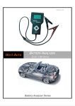
EQP-114 – Battery &
Electrical System Tester
USER’S MANUAL
For testing all 12V batteries
rated in CCA, SAE, DIN, JIS#, IEC, EN and CA.
Also for testing vehicle Electrical System.
2
EQP-114 User’s Manual
Table of Contents
1.0 Introduction-----------------------------------------------------------------------------------------
1.1 EQP-114 (Battery & Electrical System Tester) -------------------------------------------------------3
1.2 Specifications ---------------------------------------------------------------------------------------------------4
2.0 Safety Measures-----------------------------------------------------------------------------------
2.1 Safety Precautions --------------------------------------------------------------------------------------------5
2.2 Other Precautions ---------------------------------------------------------------------------------------------6
3.0 Working with Batteries-------------------------------------------------------------------------- 7
4.0 The Battery & Electrical System Tester-----------------------------------------------------
4.1 EQP-114 ---------------------------------------------------------------------------------------------------------- 9
4.2 Key Functions ---------------------------------------------------------------------------------------------------9
4.3 Functions of Individual Key--------------------------------------------------------------------------------10
5.0 EQP-114 Setup --------------------------------------------------------------------------------
5.1 Printer Installation --------------------------------------------------------------------------------------------11
5.2 Select Display Language ---------------------------------------------------------------------------------- 11
6.0 HELP Key ---------------------------------------------------------------------------------------- 12
7.0 Battery Test --------------------------------------------------------------------------------------
7.1 Start Testing ---------------------------------------------------------------------------------------------------15
8.0 Battery Rating Charts-------------------------------------------------------------------------8.1
8.2
8.3
8.4
Japanese Industrial Standards (JIS#) Rating Chart-----------------------------------------------27
DIN & EN Standards Rating Charts---------------------------------------------------------------------28
YUASA Battery Rating Chart -----------------------------------------------------------------------------30
Rough CCA Guide------------------------------------------------------------------------------------------- 31
9.0 Grounding Test ---------------------------------------------------------------------------------
9.1 Start Testing----------------------------------------------------------------------------------------------------31
10.0 Starter Test -------------------------------------------------------------------------------------
10.1 Begin Testing--------------------------------------------------------------------------------------------------37
11.0 Alternator Test----------------------------------------------------------------------------------
11.1 Start Testing----------------------------------------------------------------------------------------------------41
No load testing at 3,000 RPM-----------------------------------------------------------------------------41
Testing with load at 2,000 RPM--------------------------------------------------------------------------44
12.0 View Last Test Results----------------------------------------------------------------------- 47
12.1 Printing the Last Test Results----------------------------------------------------------------------------49
13.0 PC Link --------------------------------------------------------------------------------------------
13.1 Installing Driver------------------------------------------------------------------------------------------------50
13.2 Printing Results from Normal Printer------------------------------------------------------------------52
13.3 Saving results--------------------------------------------------------------------------------------------------52
14.0 Warranty Information---------------------------------------------------------------------------14.1 Limited Warranty----------------------------------------------------------------------------------------------53
14.2 Limitations of Warranty-------------------------------------------------------------------------------------54
EQP-114 User’s Manual
1.0 - Introduction
1.1 – EQP-114 (Battery & Electrical System Tester):
This device uses modern technology in battery testing which can test batteries
in all conditions. Testing procedures are quick and easy with repeatable results.
Test Results can be printed directly on attached mobile printer or it can be
stored in the computer for records.
1. Battery Test:
Analyses the battery condition using microprocessor controlled testing
methods without the need of fully charging it before test.
The unit consumes very little current during testing hence the test can
be repeated numerous times without worry of draining the battery and
its results are highly accurate.
Extremely safe as it does not create any sparks during clamp on and it
takes less than 7 seconds to obtain the full analysed results of tested
battery.
2. Grounding Test:
Analyses the condition of the electrical return circuit contacts resistance
which were connected to the engine or chassis body from the battery
terminal with results and recommendations display after test.
3. Starter Test:
Checks the cranking effectiveness of the battery to predict when the
battery will fail to crank a vehicle basing on voltage profiles with results
and recommendations display.
4. Alternator Test:
This test checks the alternator charging condition during load at
2,000 RPM and without load at 3,000 RPM with results and
recommendations displayed after each test.
This tester is maintenance free and does not require internal batteries. It powers
up when connected to the battery posts during testing or through an external
12 Volts DC source for later review of the test results.
3
4
EQP-114 User’s Manual
The operation is fast and simple. When connected to the battery posts,
the instructions on the screen will lead you through. There is a warning tone to
caution you to perform the correct steps. In the event that you need assistance
there is a
?
key. It will display information about each function when selected.
The results are consistent and repeatable and can be performed numerous times
without heating up the unit. It is very safe as it does not create any sparks when
connecting to the battery terminals during testing on the vehicle.
After the test, the results will be stored in its memory and can be reviewed again
later. Also it can be printed directly on the attached mobile printer. It is equipped
with a USB cable to be connected to a PC to store the results or have it printed
out from a normal computer printer.
1.2 Specifications:
Operating Voltage:
9V ~ 15V DC (max)
Analysing Capacity (Amps):
CCA:
EN:
JIS#:
SAE:
CA:
DC Volts Accuracy:
± 2% Reading
Battery analysing time:
Less than 7 seconds.
Languages:
Multiple language options are available.
PC connection:
Through USB cable.
Printer head:
Thermo print head.
Paper width:
57.5mm ± 0.5mm
Paper roll diameter:
Max. 40mm OD.
Printing Speed:
50mm per sec.
Working Temperature:
0ºC ~ 50ºC.
Working Humidity:
10 ~ 80 %
100 ~ 1700
100 ~ 1700
100 ~ 1700
100 ~ 1700
100 ~ 1700
IEC:
DIN:
100 ~ 1000
100 ~ 1000
EQP-114 User’s Manual
5
2.0 Safety Measures:
For safety reasons, read this manual thoroughly before operating the device.
Always refer to and follow the safety instructions and testing procedures provided
by the car or equipment manufacturer. The safety messages presented below and
throughout this userʼs manual are reminders to the operator to exercise extreme
care when using this test instrument.
2.1 Safety Precautions:
When the engine is running, it produces carbon monoxide, a
toxic and poisonous gas. Always operate the vehicle in a well
ventilated area. Do not breathe exhaust gases – they are
hazardous that can lead to death.
To protect your eyes from propellant object such as caustic
liquids, always wear safety eye protection.
Fuel and battery vapors are highly flammable.
DO NOT SMOKE NEAR THE VEHICLE DURING TESTING.
When engine is running, many parts (such as pulleys,
coolant fan, belts, etc) turn at high speed. To avoid serious
injury, always be alert and keep a safe distance from these
parts.
Before starting the engine for testing or trouble shooting,
always make sure the parking brake is firmly engaged.
Put the transmission in PARK (automatic transmission)
or NEUTRAL (manual transmission).
Always block the drive wheels.
Never leave vehicle unattended while testing.
6
EQP-114 User’s Manual
Never lay tools on vehicle battery. You may short the
terminals together causing harm to yourself, the tools or the
battery.
Engine parts become very hot when engine is running. To
prevent severe burns, avoid contact with hot engine parts.
Do not wear loose clothing or jewelry while working on
engine. Loose clothing can get caught in fan, pulleys, belts,
etc. Jewelry can conduct current and can cause severe
burns if it comes in contact between power source and
ground.
When the engine is running, be cautious when working
around the ignition coil, distributor cap, ignition wires and
spark plugs. They are HIGH VOLTAGE components that can
cause electrical shock.
Always keep a fire extinguisher readily available and
easily accessible.
2.2 Other Precautions:
•
This device is for testing 12 Volt batteries only.
•
Its operating voltage is from 9V ~ 15V DC and should not be used on
24V directly. It will damage the unit. For 2 x 12V batteries (in series or
parallel), disconnect the connections and test them individually.
•
Battery that has just been charged by the charger contains surface charge
and it should be discharged by turning ON the Head lights for 3~5 minutes
before testing.
•
Always attach the clips on the lead side of the battery terminal posts
during testing so that it has a good contact. This will provide better and
accurate results.
•
Do not attach the clips directly onto the steel bolt that tightens to the
battery terminal posts; this may give inaccurate readings or inconsistent
results. (Note: This also applies to all other battery testing methods.)
EQP-114 User’s Manual
•
If the battery terminal posts are oxidised or badly corroded and
the connections are bad, the tester will prompt you to check the
connections. In this case, clean the terminal posts and perform
the test directly on the terminal posts themselves.
•
During testing of the battery while it is still in the car, make sure the
engine is OFF.
•
Do not store near high humidity or temperature area. Exposing to
extreme temperatures will cause damage to the unit.
3.0 Working with Batteries
Lead-acid batteries contain a sulfuric acid electrolyte, which is a highly corrosive
poison and will produce gases when recharged and explode if ignited and cause
bodily harm.
When working with batteries, make sure you have plenty of ventilation, remove
your hand jewelry, watch and wear protective eyewear (safety glasses), clothing,
and exercise caution.
Do not allow battery electrolyte to mix with salt water. Even small quantities of this
combination will produce chlorine gas that may harm you.
Whenever possible, please follow the manufacturer's instructions for testing,
jumping, installing, charging and equalising batteries.
Never disconnect a battery cable from a vehicle with the engine
running because the battery acts like a filter for the electrical
system.
Unfiltered [pulsating DC] electricity can damage expensive
electronic components, e.g. emissions computer, radio, charging
system, etc.
7
8
EQP-114 User’s Manual
Turn off all electrical switches and components; turn off the ignition
before disconnecting the battery.
For non-sealed batteries, check the electrolyte level. Make sure it is
covering the plates, and it is not frozen before starting to recharge
(especially during winters).
Do not add distilled water if the electrolyte is covering the top of the
plates because during the recharging process, it will get warm and
expand. After recharging has been completed, recheck the level.
Reinstall the vent caps BEFORE recharging, recharge ONLY in wellventilated areas, and wear protective goggles.
Do NOT smoke or cause sparks or flames while the battery is being
recharged because batteries give off explosive gases.
If your battery is an AGM or a sealed flooded type, do NOT recharge
with current ABOVE 12% of the battery's RC rating (or 20% of the
ampere-hour rating).
Gel cells should be charged over a 20-hour period and never over
the manufacturer's recommended level or over 14.1 Volts DC.
Follow the battery and charger manufacturer's procedures for
connecting and disconnecting cables and other steps to minimize
the possibility of an explosion or incorrectly charging the battery.
You should turn the charger OFF before connecting or
disconnecting cables to a battery.
Do not wiggle the cable clamps while the battery is recharging,
because a spark might occur, and this could cause an explosion.
Good ventilation or a fan is recommended to disperse the gases
created by the recharging process.
If a battery becomes hot, over 43.3°C (110°F), or violent gassing or
discharge of electrolyte occurs, turn the charger off temporarily or
reduce the charging rate.
When charging the battery in the car with an external MANUAL
charger, make sure that it will not damage the vehicle's electrical
system or components with high voltages.
Even if this is a remote possibility, it is best to disconnect the
vehicle's battery cables from the battery BEFORE connecting
the charger.
EQP-114 User’s Manual
9
4.0 – The Battery & Electrical System
4.1 – EQP-114
Figure 1
Black Clamp
to battery
negative (–) post.
Detachable
Mobile
Printer.
Red Clamp
to battery
positive (+) post.
USB port
for connection
to PC.
4.2 – Keypad Functions:
7
Figure 2
?
6
8
1
4
2
3
5
EQP-114
10
EQP-114 User’s Manual
4.3 - Functions of Individual key:
1.
Use this key to scroll up to the next item OR when it is in the
keying-in Battery Ratings values mode, pressing this key once
will increase the value by step of 5 units.
2.
Use this key to shift the selection tab to the right item OR
when it is in the keying-in Battery Ratings values mode, pressing
this key once will increase the value by step of 100 units.
3.
Use this key to scroll down to the next item OR when it is in
the keying-in Battery Ratings values mode, pressing this key
once will decrease the value by step of 5 units.
4.
Use this key to shift the selection tab to the left item OR when
it is in the keying-in Battery Ratings values mode, pressing this
key once will decrease the value by step of 100 units.
5.
Pressing this ENTER key once will get into the selected function
or proceed to the next step.
6.
To EXIT the function, pressing this key one will return
the previous screen.
7.
8.
?
This is the HELP key. Pressing this key will enter into the
help menu and it will explain the functions of the item
you have selected in detail.
Press this key to print all the Test results on the
Detachable Mobile Printer. The printing can be done only in
View Last Test mode because here you have to check the final
results before executing a printout.
EQP-114 User’s Manual
11
5.0 – EQP-114 Setup
5.1 – Printer Installation
1. To install the mobile printer, first remove the detachable back cover of the
tester by sliding outward (Fig.3a). Then insert the mobile printer into the slot
and push all the way in until it stops (Fig. 3b),
Figure 3a
Figure 3b
2 Open the printer cover. Place a screw and tighten to secure printer as shown
(Fig.4a). Place the thermo paper roll into the slot with the paper edge facing
up (Fig.4b). Make sure the paper protrudes about 20mm when the printer
cover is closed (Fig. 4c).
Insert a screw
and tighten.
Figure 4a
Figure 4b
Figure 4c
5.2 – Select Display Language
The display language of the tester can be changed from the wake-up screen
(Fig.5). First go to Setup Menu by pressing
and then press
key to enter
key until it has been highlighted
12
EQP-114 User’s Manual
Select Menu
New: Clear Memory
Continue Testing
View last Test
Figure 5
Setup Menu
Then press [Enter].
Inside the Setup Menu (Fig.6), press
(Fig.7).
to gain access to the Language Menu
Setup Menu
Select Language
Language
LCD Brightness
Printer
PC Link
English
Deutsch
Español
Italiano
[Enter] to proceed. [Exit]
to quit.
[Enter] to save.
Figure 6
Figure 7
Select the preferred language by pressing
confirm it by pressing
key to scroll to the item. Then
save. Once it had been saved, the display will change
to the language selected. Press
key to exit and get back to the Main menu
screen (Fig.5) to continue your test.
6.0 – Help Key
This selection helps you to familiarise with the usage of the EQP-114 as well as
explaining the various test functions and results. To get into this function, just
press
?
key at any one of the functions displayed on the menu screens as
shown below (Fig.8 and Fig 9):
EQP-114 User’s Manual
Figure 8
13
Select Menu
Select Test
New: Clear Memory
Continue Testing
View last Test
Battery Test
Grounding Test
Starter Test
Alternator Test
Setup Menu
Figure 9
Then press [Enter].
Then press [Enter].
EXIT
For Example:
If help is needed on “Battery Test”, then press
the display will change to as shown (Fig 10).
?
key on this item and
Battery Test
Figure 10
How to operate
Voltage
Battery ratings
Internal R.
LIFE
Press [Help] to read
[Exit] to menu.
Pressing the
key will scroll down to the next item “Voltage” (Fig. 11 below)
and so forth until it reaches “Life”.
Battery Test
Figure 11
How to operate
Voltage
Battery ratings
Internal R.
LIFE
Press [Help] to read
[Exit] to menu.
14
EQP-114 User’s Manual
To see the help text, press
on the screen.
If you need to quit, just press
?
key again on the selected item and it will display
key will go back to the main menu (Fig. 5).
Let’s say you need help on “How to operate”. Pressing
will get into the display as shown below:
Figure 12
?
key in this selection
How to operate
Operation:
Engine must be OFF.
Locate the battery.
Clamp Tester to Battery
[+] and [-] posts. Check
battery rating [CCA,
SAE, JIS, DIN, IEC, EN,
CA].Key the rating
values. The Tester will
lead you through the
whole testing process.
Press
key will scroll down to the next page to continue reading the text
(Fig. 13) below.
Figure 13
posts. Check battery
rating [CCA, SAE, JIS,
DIN, IEC, EN, CA].Key
the rating values. The
Tester will lead you
through the whole
testing process.
[Exit] to menu.
If you wish to continue help on rest of the item like “Voltage, Battery ratings, Internal
Resistance and LIFE”, press
key anytime to go back to the main menu (Fig. 11).
Here just select the item you want with
key and then press
into the display screen with the explanation text.
To exit press
(Fig.5)
?
key will enter
key twice. You will go back to the main menu to begin testing.
EQP-114 User’s Manual
15
7.0 - Battery Test
7.1 – Start Testing
Performing Battery Test whilst it is still in the car:
Vehicle that was running has to have its engine OFF first and then switch ON the
headlights for 30 seconds to remove the surface charge. After the headlights are
switched OFF, let the battery rest for at least 1 minute to recover before testing
commences.
The engine and all other accessory loads must be OFF during test in order to
have accurate results. When attaching the tester clips, make sure that the battery
posts are not oxidized or badly corroded. Clean them first before clamping to it.
Do not clamp onto the steel bolts directly which may give inaccurate and
inconsistent results.
Testing on stand-alone batteries:
Clean the battery posts with a wire brush prior testing. For side post batteries,
install stud adaptors. Do not use steel bolts for better results.
1. Attach the tester clips onto the battery terminal posts [ Red to (+) and
Black to (–) ] the unit will power up and light up.
2. It will run through a self-test and when completed it displays the Main Menu
as shown: (Fig. 15)
16
EQP-114 User’s Manual
Select Menu
Figure 15
New: Clear Memory
Continue Testing
View last Test
Setup Menu
Then press [Enter].
Here, it will let you select your choice from the Menu:
New: Clear Memory
Selecting this item will allow the tester to clear the last tested results
stored in its memory and begin a new test.
Continue Testing
Selecting this item will allow you to continue the last test on the same car
from where you had stopped.
For example:
If you had done Battery Test and later you wish to do Alternator Test or
Grounding Test on the same car, just select this item and it will update the
results after each test in its memory so that it can be reviewed later or
be printed out.
View Last Test
Here it will let you review all the test results of the last tested car.
The results stored will always be the updated ones which depend on
the tests that had been done.
Use
or
keys to scroll for the pages during viewing.
Examples:
Figure 16
Battery: Good
Results: High Ohms
Measured: 406 CCA
Rating: 630 CCA
Volts: 12.45 V
Int. R: 6.72 mOhm
Life: 76 %
The grounding
resistance of the
engine or car chassis
is high.
Clean the cable
contacts or replace
cable if necessary.
Figure 17
EQP-114 User’s Manual
17
3. After you have made your choice, selecting “New: Clear Memory” or
“Continue…Test” will proceed to the display below: (Fig. 18)
Select Test
Figure 18
Battery Test
Grounding Test
Starter Test
Alternator Test
Then press [Enter].
4. Pressing
to select it.
key once will scroll down to the next item if there is a need
5. As an example (Fig.18) the selected item was on “Battery Test” and it is
being highlighted.
6. Press
key will proceed to do the battery testing and if it has detected
any surface charge on the battery, it will start to remove and a message is
shown (Fig. 19) below.
The Tester is removing
the battery surface charge
now.
Figure 19
Please wait for a
moment!
18
EQP-114 User’s Manual
7. If the surface charge is too great for the tester to handle, it will prompt you
with the instructions as shown: (Fig. 20) below.
Battery surface charge is
present!
Figure 20
Turn the ignition key to
ON position.
Switch ON the
headlights to remove
surface charge.
8. Wait until the surface charge removal has completed. The device will
advise as follows: (Fig.21) and then press
key.
Battery surface charge
has been removed.
Figure 21
Turn ignition key to OFF
position.
Switch OFF the
headlights and then press
[Enter].
9. If there is no surface charge present, it will enter into
“Select Battery” menu screen as shown in Fig. 22
Select Battery
SLI (Wet Type)
AGM (Flat/Spiral)
Figure 22
[Enter] to proceed
EQP-114 User’s Manual
19
Here, selecting SLI (Wet type) battery meant that it tests Starting, Lighting
and Ignition (SLI) batteries e.g. normal flooded types like Wet Low
Maintenance (Sb/Ca), Wet Standard (Sb/Sb) Batteries.
If AGM (Flat/Spiral) is selected, then it will test Wet (MF) Maintenance Free
(Ca/Ca), AGM/Gel Cell VRLA (Ca/Ca) Batteries.
10. Once the selection has been done, it will proceed to the display as shown
in Fig 23:
Select Rating
Figure 23
CCA
SAE
DIN
JIS
IEC
EN
CA
Unknown
11. Before selecting the ratings ʻCCA, SAE, EN, IEC, DIN, CA and JIS #ʼ from
the menu, check the battery specification value. This value can be checked
on the battery labels as some of the examples shown below:
20
EQP-114 User’s Manual
If it is selected under JIS # (Japanese Industrial Standard) then the display
will prompt you as shown (Fig.24) below.
Figure 24
Please refer to the charts
provided for converting
JIS# to CCA ratings
before keying in the
values.
Press [Enter] to
continue...
Refer to the battery model (example: 80D26L or NX110-5L) on the Cold
Cranking Amps (CCA) Table list supplied separately or from this manual
on page 27 & 28 (See example Fig.25 below.)
Figure 25
EQP-114 User’s Manual
Press
21
key and the display will show: (Fig.26) below:
Input Battery Rating
Increase/decrease:
Single digit
By hundredth
500 CCA
Figure 26
Press [Enter] to proceed.
12. Referring to the Table list (Fig.25) basing on 80D26L, check the battery
type: WET, MF, Sealed MF or Closed MF (CMF) as each category has
different CCA ratings. For instance, if the battery is a Sealed MF (CMF)
then it is rated at 630 CCA.
Note:
WET
MF
SMF
-
Wet Cell Type
Maintenance Free Type
Closed or Sealed Maintenance Free
13. To enter the value 630, press
key will increase the original value of 500
(Fig.26) by step of 100 units to 600. Likewise use
key to increase the
last two digits (00) to 30 by step of 5 units for each pressing. (Fig. 27)
Input Battery Rating
Increase/decrease:
Single digit
By hundredths
630 CCA
Figure 27
Press [Enter] to proceed.
22
EQP-114 User’s Manual
Once the CCA rating of the battery is confirmed, press
testing process. Refer to the display below (Fig. 28).
key will start the
Analysing ...
Figure 28
Please wait!
14. For less than 7 seconds, the results of the testing will be displayed on the
LCD screen. (Fig. 29)
2
6
Battery: Good
1
Measured: 406 CCA
Rating: 630 CCA
Volts: 12.45 V
Int. R: 6.72 mOhm
Life: 76%
3
4
5
Figure 29
Interpretations of the above results:
1.
RESULTS: Good
A very straight forward display of the final results basing on the
evaluation of the tested condition. ʻGoodʼ indicates the battery in
good condition. ʻReplaceʼ indicates that the battery needs to be
replaced. If not, the battery will fail anytime without any warning.
EQP-114 User’s Manual
2.
23
Volts : 12.45V
The volts here indicated the State of Charge (SOC) of the tested
battery which is 12.45V during open circuit condition. [Slightly
above 80% SOC for Flooded (Lead Acid) batteries by referring to
the table below.]
SOC
100 %
90 %
80 %
75 %
50 %
Wet - Flooded
(Sb/Ca, Sb/Sb)
12.60V or higher
12.58 V
12.44 V
12.40 V
12.20 V
AGM(Flat/Spiral)
AGM (Gel)
Wet MF (Ca/Ca)
12.80V or higher 12.85V or higher
12.72 V
12.77 V
12.64 V
12.69 V
12.60 V
12.65 V
12.30 V
12.35 V
3.
Measured: 406 CCA
It means that the battery tested has a capacity of 406 CCA power
available. CCA ratings has been used here, therefore the tested
result is in CCA and if other rating (DIN, SAE, JIS, IEC, CA, or EN)
were selected, it will base on the respective rating to calculate and
show the results in that selected rating.
4.
Rating: 630 CCA
This is the battery capacity rated output which was stated on the
label. Refer page 19 on how the rating is obtained.
Please take Note:
This output value (406 CCA) is related to the actual power available
in the battery in relation to that battery's rating (630 CCA). On
average, a new battery's CCA as measured by this will read 10-15 %
higher than its stated rating.
As the battery ages, the CCA number measured by this will
decrease so it reads near its rating. While this value is not the same
as a CCA test, it is the best available measurement for showing a
battery's current condition in relation to its rating.
From the above example, a 630 CCA rated battery measuring 406
CCA available power does not mean that the battery would pass a
CCA test at 406 CCA. The available power reading shows that the
battery is not able to perform up to its rated ability (630 CCA).
In comparison to another battery when fully charged, the 630 CCA
battery measuring 406 CCA is no stronger than a 400 CCA battery
showing 400 CCA available power when fully charged.
The available power number is meant for comparison to its own
rating. In fact, in this example the 630 CCA battery is failing to
perform to its rating, while the 400 CCA battery is still working.
24
EQP-114 User’s Manual
Basing on SAE, CCA test is a manufacturing process control test
applicable only on new, fully charged batteries. It does not produce
an actual value, but is a PASS / FAIL test.
It measures the discharge load, in amps, that a battery can supply
for 30 seconds at 0°F/-18°C while maintaining a voltage of 1.2 volts
per cell (7.2 volts per battery) or higher.
Thus, the CCA test shows the minimum power requirement for the
battery as rated, which means a battery rated at 400 CCA must
measure 7.2 volts or above for 30 seconds when a load of 400 amps
is applied at 0°F/ -18°C.
The above methods also hold for DIN, IEC, JIS, EN basing on its
individual ratings.
5.
Int. R (Internal Resistance): 6.72mΩ
Ω
In normal condition, the internal resistance should fall between 2.0
mΩ ~ 15.0 mΩ. As a matter of fact, the higher the battery CCA
readings obtained the lower the internal resistance should be.
6.
LIFE: 76 %
This is an indication of the battery life expectancy in percentage. If the
life falls below 45 %, the RESULT will display “Replace” and it is time
to change to a new battery.
Explanation of the following terms used as shown on the LCD display:
•
CCA (Cold Cranking Amps) – most commonly used Standard.
CCA is a rating used in the battery industry to rate a batteryʼs ability to start
an engine in cold temperatures. This rating is the number of amperes that a
new fully charged battery can delivery at 0°F (-18°C) for 30 seconds, while
maintaining a voltage of at least 7.2 Volts for a 12V battery during cranking.
•
SAE (The Society of Automotive Engineers) Standard.
SAE has established Cold Cranking Amperes (CCA) rating for batteries as
their standard. Therefore this rating is the same as CCA rating as
mentioned above.
•
IEC (International Electrotechnical Commission) Standard.
IEC amperes rating require that at 0°F (-18°C), the number of amperes that
the 12V battery can deliver while maintaining a voltage of at least of 8.4
Volts for 60 seconds during cranking.
•
EN (European Norms) Standard.
EN amperes rating require that at 0°F (-18°C), the number of ampere that
the 12V battery can deliver while maintaining a voltage of at least 6.0 Volts
for 180 seconds during cranking.
EQP-114 User’s Manual
25
•
JIS# (Japanese Industrial Standard)
JIS # amperesʼ rating is based on Ampere Hours and is calculated using 20
hours rating. In this manual, it is using CCA ratings reference table list
provided basing on the JIS model number (See page 24 & 25).
•
DIN (Deutsches Industrie Normen) Standard.
Basing on DIN , the rating requires that at 0°F (-18°C), the 12V battery is
able to deliver the number of amperes while maintaining a voltage of at least
of 9.0 Volts for 30 seconds and 8.0 Volts for 150 seconds during cranking.
•
CA (Cranking Amperes) Rating.
This rating is the number of amperes that a new fully charged battery can
delivery at 32°F (0°C) for 30 seconds, while maintaining a voltage of at
least 7.2 Volts for a 12V battery during cranking.
•
Unknown
If you are not sure which ratings (CCA, EN, IEC, JIS or DIN) that the battery
is based on, then choose this setting. It will show the batteryʼs Voltage (State
of Charge), CCA and the Internal Resistance (m Ohm) only. This selection
can also be used to test 12V - Deep Cycle Batteries.
An example of the results display is shown below: (Fig.30)
Battery:
Measured: 220 CCA
Volts: 12.26 V
Int. R: 6.24 mOhm
Figure 30
To determine the condition of the tested Deep Cycle Batteries, refer the
Volts reading – State of Charge (should not fall below 12.60V when fully
charged for Lead Acid Batteries, 12.85V for Gel Batteries and 12.80V for
AGM Batteries) and the Internal Resistance [Int. R] of the tested battery
should not be more 15 mOhm readings.
26
EQP-114 User’s Manual
Batteries that had been left idle for long periods can still be tested with this.
To perform the test, just clamp the clips onto the battery terminals and it will
display the screen (Fig.31) as shown if its voltage falls below the normal
12.0 volts.
Figure 31
Press
Battery voltage is below
12.00 Volts!
Press [Enter] to
continue...
key to continue and the display will show: (Fig.32)
Select Rating
Figure 32
CCA
SAE
DIN
JIS
IEC
EN
CA
Unknown
Check the battery ratings and enter it as described in steps 10 to 12 (page
19~21) and the results will show as an example below: (Fig. 33 and Fig.34)
Battery: OK-Recharge
Battery: To replace
Measured: 220 CCA
Rating: 400 CCA
Volts:
11.96 V
Int. R: 12.24 mOhm
Measured: 120 CCA
Rating: 400 CCA
Volts:
10.56 V
Int. R: 20.24 mOhm
State of Charge is low!
Charge battery and test
again.
State of Charge is low!
Internal resistance is
high.
Figure 33
Figure 34
EQP-114 User’s Manual
27
Fig.33 Results shown [OK-Recharge], it indicated that the battery has to be
fully charged first before repeating the test.
For Fig.34, the Results shown [To replace], this meant that the battery
needs to be replaced as its internal plate resistance [ Int. R ] is higher than
15 mOhm.
15.
Pressing the
key at any moment will exit and return back to the
main menu screen (Fig.18).
8.0 – Battery Ratings Charts
8.1 Japanese Industrial Standard (JIS#) CCA Ratings
Battery Model (JIS#)
NEW
26A17R
26A17L
26A19R
26A19L
28A19R
28A19L
32A19R
32A19L
26A17R
26B17L
28B17R
28B17L
28B19R
28B19L
32B20R
32B20L
32C24R
32C24L
34B17R
46B24R
46B24RS
46B24LS
46B26R
46B26L
46B26RS
46B26LS
48D26R
48D26L
50B24L
50B24R
50D20R
50D20L
OLD
12N24-4
12N24-3
NT50-N24
NT50-N24L
NX60-N24
NX60-N24L
NS40S
NS40LS
NS40
NS40L
N40
N40L
NS60
NS60S
NS60LS
NS60
N50
N50L
NT80-S6L
NT80-S6
CCA Rating
WET
200
200
200
200
250
250
270
270
200
200
245
245
245
245
270
270
240
240
280
325
325
325
360
360
360
360
280
280
390
390
310
310
MF
220
220
CMF
SMF
264
264
295
295
325
325
400
400
369
360
360
420
420
420
360
360
420
420
380
380
480
480
Battery
Model (JIS#)
NEW
34B17L
34B19R
34B19L
34B19RS
34B19LS
36B20R
36B20L
36B20RS
36B20LS
38B20R
38B20RS
38B20L
38B20LS
40B20L
40B20R
42B20L
42B20RS
42B20LS
46B24L
75D31L
80D23R
80D23L
80D26R
80D26L
85B60K
85BR60K
95D31R
95D31L
95E41R
95E41L
105E41R
105E41L
OLD
CCA Rating
WET
NX110-5
NX110-5L
280
270
270
270
270
275
275
275
275
330
330
330
330
330
330
330
330
330
325
450
580
580
580
580
NX120-7
NX120-7L
N100
N100L
N100Z
N100ZL
620
620
515
515
580
580
NS40ZA
NS40ZAL
NS40ZAS
NS40ZALS
NS40Z
NS40ZL
NS40ZS
NS40ZLS
NX60-N24
NT60-N24S
NX60-24L
NX60-24LS
NS60L
N70ZL
MF
CMF
SMF
325
325
325
325
300
300
300
300
340
340
340
340
400
400
400
400
360
360
360
360
410
410
410
410
360
540
420
725
580
580
630
630
500
500
850
850
770
770
880
880
660
660
640
640
720
720
28
EQP-114 User’s Manual
Battery Model
(JIS#)
NEW
50D23R
50D23L
50D26R
50D26L
55B24R
55B24L
55B24RS
55B24LS
55D23R
55D23L
55D26L
55D26R
60D23R
60D23L
65D23R
65D23L
65D26R
65D26R
65D31R
65D31L
70D23R
70D23L
75D23R
75D23L
75D26R
75D26L
75D31R
OLD
85BR60K
85B60K
50D20R
50D20L
NX100-S6
NX100-S6L
NT80-S6S
NT80-S6LS
N50ZL
N50Z
NS70
NS70L
N70
N70L
35-60
25-60
F100-5
F100-5L
N70Z
CCA Rating
WET
500
500
435
435
430
430
355
355
350
350
520
520
420
420
415
415
390
390
490
490
500
500
490
490
450
MF
CMF
SMF
370
370
420
420
420
420
480
480
440
440
500
500
500
500
500
500
525
525
540
540
520
520
520
520
540
540
520
520
580
580
625
625
630
630
580
580
580
580
540
735
Battery Model
(JIS#)
CCA Rating
NEW
OLD
WET
105F51R
105F51
115E41R
115E41L
115F51R
115F51L
130E41R
130E41L
130F51R
130F51L
145F51R
145F51L
145G51R
150F51R
150F51L
165G51R
165G51L
170F51R
170F51L
180G51R
180G51L
195G51R
195G51L
190H52R
190H52L
245H52R
245H52L
N100Z
N100ZL
NS120
NS120L
N120
N120L
NX200-10
NX200-10L
580
580
650
650
650
650
800
800
800
800
780
780
780
640
640
935
935
1045
1045
1090
1090
1145
1145
925
925
1530
1530
NS150
NS150L
N150
NT200-12
NT200-12L
NS200
NS200L
NX250-12
NX250-12L
NT250-15
NT250-15L
NX300-51
NX300-51L
N200
N200L
NX400-20
NX400-20L
8.2 DIN & EN Standards Rating Chart
Battery
Model No.
52805
52815
53517
53520
53521
53522
53621
53624
53625
53638
53646
53653
53836
53890
54038
54039
54232
54312
54313
DIN
180
180
175
150
150
150
175
175
175
175
175
175
175
175
175
175
175
210
220
Amps
EN
240
240
300
240
240
240
300
300
300
300
300
300
300
300
300
300
300
360
330
Battery
Model No.
55057
55068
55069
55218
55414
55415
55421
55422
55423
55427
55428
55457
55529
55530
55531
55545
55548
55552
55559
DIN
320
220
220
255
265
265
265
265
300
300
300
265
220
255
255
255
255
255
255
Amps
EN
540
390
390
420
450
450
450
450
510
510
510
450
360
420
420
420
420
420
420
MF
CMF
SMF
800
800
800
800
960
960
960
960
920
920
900
1100
980
980
1100
1100
1250
1250
1300
1300
EQP-114 User’s Manual
Battery
Model No.
54317
54324
54434
54437
54449
54459
54459L
54464
54465
54466
54469
54519
54523
54524
54533
54537
54545
54551
54577
54578
54579
54580
54584
54590
54612
54801
54827
55040
55041
55042
55044
55046
55048
55056
56638
56641
55647
56821
56820
56828
57024
57029
57113
57114
57217
57218
57219
57220
57230
57412
57412L
57413
57512
57513
57531
29
DIN
210
220
210
210
210
210
210
220
210
210
210
210
220
220
210
190
190
220
220
220
220
220
220
210
210
190
240
265
220
220
265
300
300
320
300
300
300
315
315
315
315
315
400
400
420
420
420
420
380
400
400
400
350
350
350
Amps
EN
360
330
360
360
360
360
360
330
360
360
360
360
300
300
360
300
300
300
300
300
300
300
300
330
360
300
360
450
360
360
450
510
540
540
510
510
510
540
540
540
540
540
680
680
720
720
720
720
640
680
680
680
570
570
570
Battery
Model No.
55559L
55563
55564
55565
55565L
55566
55567
55811
56012
56048
56049
56068
56069
56073
56077
56091
56092
56111
56216
56218
56219
56220
56225
56311
56312
56318
56322
56323
56420
56530
56618
56619
56620
56633
60026
60038
60044
60527
60528
61017
61018
61023
61047
61048
62034
62038
62045
62529
63013
63545
63549
64020
64028
64035
64036
DIN
255
255
255
255
255
265
255
360
230
250
250
250
250
250
300
360
300
300
300
300
300
280
300
300
300
300
300
300
300
300
300
300
300
300
440
500
500
410
410
400
400
450
450
450
420
420
420
450
470
420
420
325
520
520
460
Amps
EN
420
420
420
420
420
450
420
540
420
390
390
390
390
390
510
540
510
540
510
510
510
510
510
510
510
510
510
510
510
510
510
510
510
510
720
760
760
680
680
680
680
760
760
760
680
680
680
760
680
680
680
550
760
760
760
30
EQP-114 User’s Manual
Battery
Model No
58424
58513
58514
58515
58521
58522
58527
58811
58815
58820
58821
58827
58833
58838
59017
59018
59040
59215
59218
59219
59226
59514
59518
59519
59615
59616
60018
60019
DIN
450
320
320
450
320
320
395
440
395
395
395
400
400
400
360
360
360
450
290
290
450
320
395
395
360
360
250
250
Amps
EN
760
540
540
760
540
540
640
720
640
640
640
640
680
680
600
600
600
760
480
480
760
540
640
640
600
600
410
410
Battery
Model No
64317
64318
64323
65513
65514
65515
67043
67045
68021
68032
68034
68040
70027
70029
70036
70038
71014
71015
72512
73011
88038
88046
88056
88066
88156
88074
88092
DIN
540
540
540
540
570
570
600
600
570
600
600
570
630
630
570
630
700
700
680
740
175
210
265
300
320
400
400
Amps
EN
900
900
900
900
900
900
1000
1000
950
1000
1000
950
1050
1050
950
1050
1150
1150
1150
1200
300
360
450
510
540
680
680
8.3 YUASA Battery Rating Chart
Battery
Model No.
24-500
34-6MF
34-60
34-610MF
34-710
35-580
41-580
55D23R
58-6MF
58-60
58-530
65-70
CCA
500
500
525
610
710
580
580
522
530
525
530
700
Battery
Model No.
65-730
65-900
74-60
75-6MF
75-72
75A-72
75-660
78A-72
78-710
GR40R-MF
GR40R-CMF
GTH40
CCA
730
850
525
615
500
630
660
670
710
700
820
277
Battery
Model No.
GTH40L
GTH40S
GT50L
GTH55DL
GTH60L
GTH60DL
GTH75DL
GTH75DR
GR96R-MF
GR96R-CMF
CCA
276
275
356
356
325
325
520
521
500
580
EQP-114 User’s Manual
31
8.4 Rough CCA Guide
Given below is a rough CCA ratings guide for any unknown battery model basing
on the capacity of the vehicle:
Vehicle Capacity
Approximate Battery CCA Rating
1200 ~ 1600 cc
350 CCA
1600 ~ 2000 cc
500 CCA
2000 ~ 3000 cc
650 CCA
3000 cc and above
750 CCA
M. Benz over 3000 cc
760 CCA
9.0 – Grounding Test
The engine body and the vehicle chassis are always connected to the battery
negative terminal to provide the electrical return path (grounding) for all the
electrical components. Due to the surrounding environmental effect, the surface
contacts of these joints or connections of these circuits are subject to oxidation
and corrosion in a matter of time rendering them to have high resistance in it.
One typical example is the connection at the battery terminals where oxidation
and corrosion takes place very often. If these contacts were no good then it will
pose a lot of electrical problems to the vehicle.
By checking the ground condition, this will measure the resistance from the engine
body contact to the battery terminal then it will display the results and the
recommendations.
9.1 – Start Testing
1. Make sure that the engine is switched OFF. Attach the clips onto the battery
terminal posts and the unit will power up and lights up the LCD display screen.
32
EQP-114 User’s Manual
2. It will run through a self-test and when completed it displays the Main Menu
as shown: (Fig. 36)
Select Menu
Figure 36
New: Clear Memory
Continue Testing
View last Test
Setup Menu
Then press [Enter].
3. After you have made your choice, selecting “New: Clear Memory” or
“Continue…Test” will proceed to the display below: (Fig. 37)
Select Test
Figure 37
Battery Test
Grounding Test
Starter Test
Alternator Test
Then press [Enter].
4. Pressing
key once will scroll down to the ʻGrounding Testʼ (Fig.38)
Select Test
Figure 38
Battery Test
Grounding Test
Starter Test
Alternator Test
Then press [Enter]
EQP-114 User’s Manual
5. Press
33
key will proceed to the display as follows: (Fig. 39)
Grounding Test
Figure 39
Clip the Black clip to
engine body or the car
chassis and the Red clip
to the battery [+] post.
Press [Enter] to begin.
6. Now transfer the BLACK tester clip from the battery [-] terminal to a
suitable position on the engine or chassis body leaving the RED clip still
attached to the battery [+] terminal.
7. Press
key again and it will starts analyzing (Fig. 40)
Figure 40
Analysing ...
Please wait!
8. Once it has finished analysing, it will prompt you with an instruction
(Fig. 41) stating that you have should unclamp the Black clip from the
engine or chassis body and transfer to the battery negative [-] terminal
within 20 seconds time limit. If you don’t, the testing procedure has to
be repeated as the gathered data will be lost.
34
EQP-114 User’s Manual
Grounding Test
Figure 41
Now transfer the Black
clip to the battery [-]
post.
The time limit given is 20
seconds before the
memory is lost.
9. Once the Black clip is clamped onto the battery [-] terminal, the tester
display will light up as shown. (Fig. 42)
Grounding Test
Figure 42
10. Now you need to press
follows (Figure 43).
Press [Enter] to continue
the test.
key to proceed and the display will show as
Analysing ...
Please wait!
Figure 43
EQP-114 User’s Manual
35
11. If the measured resistance reading is within limits, then it will display as
follows (Fig. 44)
Results: OK
Figure 44
The grounding resistance
of the engine or car
chassis is within limit.
12. If the measured resistance reading has gone beyond the limits, then it will
display the screen as follows (Fig. 45).
Results: High Ohms
Figure 45
Note:
The grounding resistance
of the engine or car
chassis is high.
Clean the cable contacts
or replace cable if
necessary.
The above indicates that the ground contact from the engine body to
the battery is bad. Check for rusted or corroded point of contacts.
If found, dismantle it for cleaning or replacement before reinstalling
the battery. Repeat the test again after fixing.
Another thing is that if you suspect that the result is in question, you
may conduct the test with the Black clip clamp at a different location.
36
EQP-114 User’s Manual
13. If you did not follow the right procedures during the testing, it will display
the results as follows (Fig. 46) below:
Results: Not detected
Wrong procedures.
Try again and follow the
step by step instructions
given.
Figure 46
14. To exit the program, pressing the
key at any moment will exit and
return back to the main menu screen (Fig.38).
10.0 – Starter Test
This test actually checks the cranking effectiveness of the battery and also
can predict when the battery will fail to crank a vehicle.
This is designed to address the weakness of conventionals with its
cranking power measurements. Simply connect the analyzer to the battery
in the vehicle and start the engine!
To understand the working principle of the tests, letʼs look at the wave form
displays taken during the cranking tests with an oscilloscope.
EQP-114 User’s Manual
37
Figure (A) above shows the voltage profile of a healthy battery during the
cranking of an engine. The graph starts off at the battery's nominal voltage,
and a voltage drop is detected when the vehicle is cranked. The voltage
recovers to the battery's nominal voltage and eventually rises to
approximately 14.4 V when the alternator starts charging the battery.
For Figure (B) where a typical 2 year-old battery, you noticed the difference
in the voltage drop which indicates that it is weaker but still usable.
Whereas Figure (C) represents a very weak battery that can barely crank a
car and is due to fail in the very near future.
As voltage profiles can indicate the relative ability of the tested battery in
starting an engine, so there is no need for knowledge on the starter motor
requirement or the battery's rating and size.
The EQP-114 will capture the highest voltage drop and calculate the
final results which should not be lower than 9.6V average during cranking
and computes the result after the test.
10.1– Begin Testing
1. With engine OFF, place the vehicle transmission in NEUTRAL for Manual
and PARK for Automatic then apply the parking brake.
2. Connect the tester to the battery terminals and the display will light up.
3. After you have made your choice, selecting either “New: Clear Memory” or
“Continue…Test” will proceed to the display below: (Fig. 48)
38
EQP-114 User’s Manual
Select Menu
Figure 48
New: Clear Memory
Continue Testing
View last Test
Setup Menu
Then press [Enter].
4. From the main MENU, select ʻStarter Testʼ by scrolling down using
key. The screen will show (Fig.49).
Select Test
Figure 49
Battery Test
Grounding Test
Starter Test
Alternator Test
Then press [Enter].
2. Press
key to continue and the display will show: (Fig.50)
Starter Test
Battery: 12.45V
Figure 50
Crank engine now until it
starts. Then press [Enter].
3. Switch the ignition key to ON and start cranking the engine until it starts.
Immediately after that press
as follows (Figure 51):
key and the results will show
EQP-114 User’s Manual
39
Result: OK
Min. Volts: 10.56V
Volt Drop: Normal
Figure 51
Press [Exit] to main
menu.
4. If the voltage drop is too great during the cranking, the tested results
will display as follows (Figure 52) and will prompt you to check the
starter system.
Result: High Drop
Min. Volts: 8.56V
Volt Drop: High
Figure 52
Check starter relay,
battery terminals or
battery has aged.
Press [Exit] to main
menu.
5. During cranking when it detects that there is no drop in voltage, it will
display the following screen (Figure 53).
Result: Not detected
Figure 53
No change in volt drop.
Check clamping at
battery side and test
again.
Press [Exit] to main
menu.
6.
Pressing the
key at any moment will exit and return back to the
main menu screen. (Fig.49)
40
EQP-114 User’s Manual
11.0 – Alternator Test
An alternator is the device used to produce the electricity the car needs to run
and to keep the battery charged. The alternator uses the principle of
electromagnetic induction to produce voltage and current. The four main parts
of the alternator are the Rotor, Stator, Diode Pack, Voltage Regulator and an
Ammeter or Indicator Light to inform the driver of any problems. All of these
parts must be in good working order for the alternator to do its job.
The Rotor is a coil of wire wound around an iron core. The Rotor rotates as
the alternator shaft rotates and current passes through brushes. The Rotor
winding passes the Field current. This causes the Rotor to produce a
magnetic field. So basically the Rotor is a rotating electro magnet.
The Stator is a set of three windings fixed to the case of the alternator and
these windings are static i.e. they donʼt rotate. As the Rotor rotates its
magnetic field “cuts” each Stator winding in turn, this induces a current in each
winding. The outputs from the Stator windings are 120 degrees apart and are
alternating current (AC).
But vehicles run on DC current, so we need something that will convert the AC
current to DC current. This is the job of the diode pack. A diode is an electrical
one-way check valve that will let current flow in only one direction. The typical
diode pack uses four diodes to accomplish this. AC current is feed in on one
side of the diode pack and DC current comes out the other side. The diode
pack here will rectify the alternating 3 phases from the Stators and combine
them into a single Direct Current which also works the dash ammeter or
indicator light.
Now that we have a DC current that the vehicle can use, we need a way to
control that current. That is the job of the voltage regulator. As the name
implies, it regulates the voltage going to the battery. It does this by turning
current to the field (stator) terminal of the alternator on and off.
If the battery voltage goes below 13.5 volts, the voltage regulator sends
current to the field terminal and allows the alternator to start charging. Current
will then flow into the battery and bring it up to full charge.
If the voltage goes above 15.0 volts, the voltage regulator shuts off the current
to the field terminal and keeps the battery from overcharging and cooking
itself. This is how the voltage regulator controls the alternator output.
EQP-114 User’s Manual
41
When you first start your vehicle, the alternator needs some current to start
working. The voltage regulator supplies this current from the battery to the
field (stator) terminal of the alternator to get it started.
The state of charge of the battery controls amperage output of the alternator.
When the battery has a full charge, the electro-motive force of the voltage
lowers the amperage to almost zero. As the battery charge wears down, the
electro-motive force is not enough to stop the amperage, so it flows into the
battery and charges it again.
11.1 – Start Testing
This test is to check the MAX and MIN charging voltages output of the
alternator at 3000 RPM without load and 2000 RPM with all loads ON. With
this test you can determine the alternatorʼs condition when in reference with
the vehicleʼs Service Manual.
No load testing at 3,000 RPM
1. With engine OFF, place the vehicle transmission in NEUTRAL for Manual
and PARK for Automatic and apply the parking brake.
2. Attach the clips onto the battery terminal posts and it will power up and
lights up the LCD display screen.
3. It will run through a self-test and when completed it displays the Main
Menu as shown: (Fig. 55)
Select Menu
Figure 55
New: Clear Memory
Continue Testing
View last Test
Setup Menu
Then press [Enter].
42
EQP-114 User’s Manual
4. After you have made your choice, selecting either “New: Clear Memory” or
“Continue…Test” will proceed to the display below: (Fig. 56)
Select Test
Figure 56
Battery Test
Grounding Test
Starter Test
Alternator Test
Then press [Enter].
5. Pressing
key to scroll down to the ʻAlternator Testʼ (Fig.57)
Select Test
Figure 57
Battery Test
Grounding Test
Starter Test
Alternator Test
Then press [Enter]
6. Press
key to continue and the display will show: (Fig.58)
No Load Test
Start the car engine and
keeps it running.
Figure 58
Then press [Enter] to
begin.
EQP-114 User’s Manual
43
Start the engine and then press
prompt you as shown below (Fig. 59).
Figure 59
key again and the screen will
No Load Test
Make sure all electrical
loads are turn OFF. Rev
the engine to 3,000 rpm.
Press [Enter].Hold on to
this 3,000 rpm for 10
seconds and release the
pedal.
Follow the instructions, make sure that all loads (lights, air-conditioning, etc)
are OFF. Rev the engine up to 3,000 ~ 3,500 RPM then press
key
and maintain the engine speed for about 10 seconds and release the pedal.
The maximum and minimum voltages values will be captured.
After that press
key again and it show as below (Fig 60.)
No Load Test
At 3,000 rpm:
Charging Volts
range limit.
Av Volts: 14.2V
<15.0V: Max. 14.6V
>13.3V: Min. 13.8V
Average
Charging Volts
Captured Volts
readings
Press [Enter] for results.
Figure 60
With the captured readings, analysis can be done by referring to
the limits as indicated that MAX voltage should not exceed 15.0V
(max. voltage at 3,000 RPM) and MIN voltage should be more
than 13.3V (min voltage during idling speed).
44
EQP-114 User’s Manual
7. Press
key will show the results of the test (Figure 61):
Results: Good
At 3,000 rpm,
No load Test:
Average Charging Volts:
14.2V
Press [Enter] to continue
to Loading Test.
Figure 61
8. If either minimum or maximum charging volts are not within the voltage
range limits then it will display one of the screen as below (Figures 62 &
63) and it will prompt you to check the charging system for the fault.
Results: Low charge
Results:High charge
At 3,000 rpm,
No load Test:
>13.3V: Min 13.2V
At 3,000 rpm,
No load Test:
<15.0V: Max. 15.6V
Check for loose belt
and the alternator.
Check alternator and
the regulator.
Figure 62
Figure 63
Testing with load at 2,000 RPM
As more electrical accessories, such as lights, heater, air conditioning,
car stereos, etc. were used; the electro-motive force decreases and this will
allow more amperage from the alternator to flow into the battery to compensate
for the added load. This test is to check the alternatorʼs behavior during loading.
9. Continue from the previous test (either Fig. 61, 62 or 63); proceed to the
next step by pressing
key will enter to the display as follows. (Fig.64)
EQP-114 User’s Manual
45
Loading Test
Switch ON all
electrical loads. Rev
engine up to 2,000
rpm. Press
[Enter].Hold on to this
2,000 rpm for 10
seconds and release
the pedal.
Figure 64
Follow the instructions, switch ON all electrical loads (Head Lights, Radio,
Air-conditioning, Heater, etc). Rev the engine up to 2,000 ~ 2,500 RPM
then press
key and maintain the engine speed for about 10 seconds
and release the pedal. The maximum and minimum voltages values will
be captured. (Fig.65)
Loading Test
Normal Charging
range limit.
At 2,000 rpm:
Av.Volts: 13.3V
>13.5V: Max. 13.8V
>12.5V: Min. 12.8V
Press [Enter] for results.
Average
Charging volts.
Captured Volts
readings
Figure 65
With the captured readings, analysis can be done by referring to the
limits as indicated that MAX voltage should exceed 13.5V
(max. voltage at 2,000 RPM) and MIN voltage should be
more than 12.5V (min voltage during idling speed).
46
EQP-114 User’s Manual
After that press
key again and the results will be shown as below (Fig 66.)
Results: Good
At 2,000 rpm,
Loading Test:
Average Charging
Volts: 13.3V
Figure 66
10. If either minimum or maximum charging volts are not within the voltage
range limits then it will display one of the screens as below (Figures 66
& 67) and it will prompt you to check the alternator system for the fault.
Results: Low charge
Results: Low charge
At 2,000 rpm,
Loading Test:
>13.5V: Max. 13.3V
At 2,000 rpm,
Loading Test:
>12.5V: Min. 12.4V
Check for loose belt and
the alternator.
Check for loose belt and
the alternator.
Figure 67
Figure 68
key at any moment will exit
11. To exit the program, pressing the
and return back to the main menu screen (Fig.57).
EQP-114 User’s Manual
12.0
47
View Last Test Results
To view the results of the last test, EQP-114 has to be connected to an external
power source by either clamping its clips directly to a 12Volt car battery or
connected to a PC via the USB port.
Figure 69
1. Once powered up, the wakeup screen will display as follows:
2. It will run through a self-test and when completed it displays the
Main Menu as shown: (Fig. 71)
Select Menu
Figure 71
New: Clear Memory
Continue Testing
View last Test
Setup Menu
Then press [Enter].
48
EQP-114 User’s Manual
3. Pressing
key once will scroll down to the ʻView last Testʼ
Fig. 72 below.
Select Menu
Figure 72
New: Clear Memory
Continue Testing
View last Test
Setup Menu
Then press [Enter].
4. Press
key will proceed to display the last test results depends
on the type of test you had performed earlier. (Fig. 73)
Battery: Good
Figure 73
Measured: 406 CCA
Rating: 630 CCA
Volts: 12.45 V
Int. R: 6.72 mOhm
Life: 76%
5. To view the next page, press
or
key to get to the page you
want. Some examples below are: (Figs. 74, 75, 76 & 77)
Figure 74
Results: High Ohms
Result: High Drop
The grounding resistance
of the engine or car
chassis is high.
Min. Volts: 8.56V
Volt Drop: High
Clean the cable contacts
or replace cable if
necessary.
Check starter relay,
battery terminals or
battery has aged.
Press [Exit] to main
menu.
Figure 75
EQP-114 User’s Manual
49
Results: Good
At 3,000 rpm,
No load Test:
Average Charging Volts:
14.2V
Results: Good
At 2,000 rpm,
Loading Test:
Average Charging
Volts: 13.3V
Press [Enter] to continue
to Loading Test.
Figure 76
Figure 77
12.1 Printing the Last Test Results
Printing of the Last Test Results can only be done while in this View Last Test
mode. This is to ensure that the results printed will be the final ones as every test
redone will be updated in its memory.
Important:
The Tester has to be connected to a 12V battery in order to work with the
mobile printer. This is because it needs higher Amps to operate which
the PC USB output is unable to provide.
To print just press
key on the tester, the mobile printer will start printing.
Note:
To printout on normal computer printer, it has to be connected to the PC
with EQP-114 software installed. (See Print Results from Normal Printer –
Page 54).
To exit the program, pressing the
key at any moment will exit
and return to the main menu screen (Fig.71).
50
13.0
EQP-114 User’s Manual
PC Link
The PlusQuip EQP-114 is also designed to link with PC for data storage and
printout through normal printer. To do so, the PC has to install the driver and
the software provided in order to operate.
13.1 - Installing Software.
Important Note:
Before you start to install the driver, please do not plug the EQP-114 into the
computerʼs USB port or else the installation will fail and the computer
cannot detect the proper driver for the EQP-114 when connected.
If you have made the above error and wish to install the driver the second time,
you need to uninstall the previously installed driver first before starting to reinstall
again. This time make sure that the EQP-114 is not plugged in.
Step 1. 1. To download the software files visit the website
www.plusquip.com.au/downloads Select the EQP-114 software link.
2. Unzip and open the downloaded files. Install the operating system
driver (Suitable for Windows XP, Vista and 7 only) by double
clicking on the Driver Installer icon.
3. Now double click on the EQP-114 Setup file icon. Follow
instructions on screen to install the EQP-114 software.
4. Now link up the EQP-114 with your PC. In the Setup Menu display
press key to highlight “PC Link” and then press
key to activate.
Step 2.
Back to desktop, open the EQP-114 program by left clicking
the BESA icon and the display page will show as follows:
This COM port
number should
be the same as
listed on the
Device Manager.
If you find that
this field is blank,
unplug the
USB cable
and plug back
again. The COM
will appear.
Click here to put your
Company name and address.
EQP-114 User’s Manual
Step 3.
51
Now link up the EQP-114 with PC by the following procedures:
1. On the Main Menu page (Fig. 78) below, select Setup Menu by
pressing
key to highlight it and then press
key.
Select Menu
Figure 78
New: Clear Memory
Continue Testing
View last Test
Setup Menu
Then press [Enter].
2. In the Setup Menu display (Fig. 79), press
“PC Link” and then press
key to highlight
key to activate.
Setup Menu
Figure 79
Language
LCD Brightness
Printer
PC Link
[Enter] to proceed. [Exit]
to quit.
It will remain in this display while logging into the PC.
Do not press any other keys because the EQP-114
is already communicating with the PC.
3. To confirm the communication; click on [ Get Data From ] tab
and the Last Test Result will appear. See example below.
52
EQP-114 User’s Manual
You can type in
the particulars
here and then
click [Add to Test
Report] tab to be
included in the
test report which
will be stored
and printed out if
you wish.
If there is no communication, a message text box will appear:
In this case repeat Step 7 – No.2 and 3 procedures again.
13.2 Printing Results from normal printer:
While on this page, if you wish to print out the results, make sure that
your printer is connected to the computer. Click on [PRINT] tab and a
text box will appear. Select the right printer and click [Print] tab to print.
Select the
printer which is
connected to
your computer
here.
13.3 Saving Results:
If you wish to save the results from this page, then click on [SAVE] tab.
A message box will appear. Type in the file name and click [Save] tab.
Select where
you want to
save in.
Type the file
name here.
EQP-114 User’s Manual
53
Disclaimer
All information, illustrations, and specifications contained in this user manual are
based on the latest information available at the time of printing. The right is
reserved to make any changes at any time without obligation to notify any person
or organisation of such revisions or changes.
Furthermore, the manufacturer or its sales agents are not liable for errors contained
herein or for incidental or consequential damages (including lost profits) in
connection with the furnishing, performance or use of this material.
This user manual tells how to use and perform the required procedures on
vehicles. Safe and effective use of this is very much dependant on the user
following the normal practices and procedures outline in this manual.
14.0 – Warranty Information
14.1 – Limited Warranty
This limited warranty cover defects in materials and workmanship for a period
of twelve (12) months which begins from the date the product is purchased by
the end user and is subjected to the following terms and conditions:
1.
Within the warranty period, the manufacturer will repair or replace, at
their options, any defective parts and return to the owner in good
working condition.
2.
Any repaired or replaced parts will be warranted for the balance of the
original warranty or three months (3) months from the date of repair,
whichever is longer.
3.
This warranty only extends to the first owner and not assignable or
transferable to any subsequent owner.
4.
Cost of delivery charges incurred for the repair of the product to and
from the manufacturer will be borne by the owner.
5.
This limited warranty covers only those defects that arises as a result of
normal use and does not cover those that arises as a result of:
•
Unauthorised modifications and repair.
•
Improper operation or misuse.
•
Accident or neglect such as dropping the unit onto hard surfaces.
54
EQP-114 User’s Manual
•
Contact with water, rain or extreme humidity.
•
Contact with extreme heat.
•
Cables that have broken, bent contact pins or subject to extreme
stress or wear.
•
Physical damage to the product surface including scratches, cracks
or other damage to the display screen or other externally exposed
parts.
14.2 - Limitations of Warranty
Other than the foregoing limited warranty, the manufacturer does not
make any other warranty or condition of any kind, whether express or
implied.
Any implied warranty of merchantability, or fitness for use shall be limited
to the duration of the foregoing limited warranty.
Otherwise, the foregoing limited warranty is the ownerʼs sole and
exclusive remedy and is in lieu of all other warranties whether express or
implied.
The manufacturer or any of its exclusive sales agents shall not be liable
for any consequential or incidental damages or losses arising of the loss
of uses of this product.
All warranty information, product features and specifications are subjected
to change without prior notice.
Quality Products
12 Month Warranty
Technical Support
Available from leading automotive specialists and retailers.
www.plusquip.com.au