1
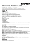
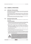
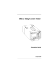
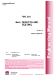
Standard Harness
User’s Guide
OMS LLC
P.O. Box 146, Montgomery, NY 12549
Phone: 845.457.1501 fax: 845.457.1504
www.omsdive.com
E-mail: [email protected]
Buoyancy Compensator
User’s Guide
Thank you for choosing OMS,
OMS buoyancy compensators have been constructed from rugged materials with unique features
adaptable to advanced underwater environments. The general design philosophy allows for complete
system integration of a number of components achieving high lift capacities, low drag, and increased safety
through redundancy. With a selection of different harnesses, different air cells and accessories, a diver can
configure his or her system for the specific environment they are operating in. This equipment is intended
for use by individuals with the training and experience to dive these environments safely
General Precautions & Warnings
•
Before using this buoyancy compensator (BC), you must receive instruction and
certification in SCUBA diving and buoyancy control from a recognized training agency.
Use of SCUBA equipment by uncertified or untrained persons is dangerous and can result in
injury or death.
•
Read this owner’s manual completely before attempting to use your BC, and become
familiar with it first in a controlled environment such as a swimming pool, in order to weight
yourself properly and to become comfortable with using its many features and adjustments.
•
Before every dive, perform a complete pre-dive inspection according to the procedure
prescribed in this manual, to ensure that all components are functioning properly and no
signs of damage or leaks are present. If you find that your BC is not functioning properly or
is damaged, remove it from service until it can be repaired.
•
Your BC is not a lift bag. Do not use it to bring heavy objects to the surface. Doing so may
cause permanent damage to the BC, and could also result in serious injury or death due to
embolism or decompression sickness.
•
In an emergency such as an out of air situation or uncontrolled descent, it is important to
remove and jettison weight immediately. Do not depend solely on using your BC’s power
inflator to lift you to the surface.
•
In the event of an uncontrolled, rapid ascent, it is important to immediately begin venting air
from the BC. Continue venting air to slow your ascent rate if neutral buoyancy cannot be
reestablished.
•
Do not inhale from your oral inflator. The BC may contain harmful contaminants or gasses,
which could cause suffocation or injury.
•
The function of your buoyancy compensator is to help you maintain neutral buoyancy while
in a comfortably balanced, face-down swimming position underwater. It is also designed to
provide you with flotation so that you can rest on the surface, but it is not designed to
function as a life preserver or personal flotation device (PFD). A buoyancy compensator
(BC) is not a life jacket. It is not designed to provide face-up flotation in all situations, and
therefore it does not meet U.S. Coast Guard regulations for a life preserver or personal
flotation device (PFD).
•
Have your OMS equipment inspected and serviced annually by an authorized OMS dealer
or at any time you have any concerns about your equipment’s function or condition.
The Standard Harness System
The OMS Deluxe harness is perfect for those who want a quality diving harness with a single left
side quick release. The Deluxe harness is a cross shoulder harness. This means each side of the
upper harness crosses at the top (behind the divers head) then joins to the lower assemblies on the
opposite side. Top left to lower right and top right to lower left. This is a design for superior
comfort.
The harness can be assembled with any manufacturers back plate but it is recommended it be used
with the OMS Aluminum or Stainless Steel back plate due to the superior quality and softer edges.
OMS plates extend the life of the harness webbing considerably.
These instructions are broken down into sections for ease of assembly. If you have any questions,
call OMS and speak with a technical support representative.
The Standard Harness System Includes:
(Measurements and components may vary slightly)
Fig# 1. Lower Left Assembly: 60 inch length of two inch webbing, 1-SS D-ring, 1-SS slide/keeper.
(The webbing incorporates the female end of the shoulder quick release, the male end of the
chest strap buckle and a chest D-ring)
Fig# 2. Lower Right Assembly: 57 inch length of two inch webbing, 1-SS or plastic waist quick
release, 1-female crotch strap buckle/scooter ring assembly, 1-SS D-ring, 1-SS slide/keeper.
(Webbing incorporates female chest buckle and SS ring)
Fig# 3. Upper Assembly: 100 inch length of 2” webbing with a centered grommet, 1-male end of
the shoulder quick release, 2-two inch plastic slides/keepers, 3-SS D-rings, 3-SS slide/keepers.
Fig# 4. Crotch Strap Assembly: Length of one-inch webbing, 2-plastic one-inch slides/keepers, 1male end of the crotch buckle.
Fig 1
Fig 2
Fig 3
Fig 4
Assembly of the Standard Harness
Lower Harness Assemblies
Lower Left Assembly (Fig 1): Holding the 60 inch lower left assembly with the D-ring facing to
your right (when looking at the plate), insert the free end of webbing through the inside lower slot
of the divers left hand side of the plate from front to back. Now pull the webbing back through the
outer lower left hand slot from back to front. Leave approximately 14” of webbing between the
plate slot and the female quick release. Final adjustments can be made later while wearing your
exposure suit.
Lower Right Assembly (Fig 2): Insert the free end of webbing through the divers right side lower
inner most slot of the plate from front to back then string it back through from back to front. Leave
approximately 14” of webbing between the plate slot and the SS ring with female chest buckle. Be
sure buckle is facing the correct position as shown in the far right image below (writing on buckle is
facing up). Final adjustments can be made later while wearing your exposure suit.
Assembly of the Standard Harness (continued)
Upper Harness Assembly
Upper Left & Right:
Step one: String one end of the 100 inch length of webbing with the centered grommet, through the
uppermost slot of the divers left side of the plate from back to front. Pull the grommet through
along with another five inches of webbing after the grommet.
Step two: String the webbing back trough the lower angled slot from front to back (directly under
the upper slot) and pull the grommet through. Adjust so the grommet lines up with the bolthole in
the center of the back plate.
Assembly of the Standard Harness (continued)
Step three: Pull the webbing through the lower slot on the upper divers right hand side of the plate
from back to front making sure the webbing isn’t twisted once pulled through. Now string it back
through the upper most slot directly above from front to back.
Before installing the hardware, make sure the grommet on the upper assembly is centered with the
bolthole. The diver’s left hand lower assembly is positioned so as the attached D-ring is facing the
diver’s left side if webbing is on edge (see image below).
Assembly of the Standard Harness (continued)
Upper Right Hardware Assembly
Install a 2” plastic slide/keeper onto the upper right portion of the harness. Be sure that when
installed, the webbing is showing in the center portion of the slide/keeper. The slide should be
placed around 2 inches or so from the edge of the plate. Next, install the D-ring assembly by
stringing the webbing through the top slot of a SS slide/keeper from back to front. String a D-ring
through the same piece of webbing up as far as the slide/keeper so as the flat part of the ring is
touching the slide/keeper. String the webbing through the bottom slot of the slide/keeper from front
to back and pull through until the D ring is trapped between the slide/keeper and the webbing.
Adjustments can be made later while wearing your exposure suit.
String the male end of the quick release buckle paying attention that the correct side faces the diver.
The Buckle should be positioned around 17 inches from the top of the plate and just below the Dring assembly. Note the positioning in the far right image below. Adjustments should be made
later while wearing your exposure suit.
String the excess webbing through the D-ring assembly and the upper plastic keeper at the top. Trim
as necessary.
Assembly of the Standard Harness (continued)
Upper Left Hardware Assembly
Install a plastic 2” slide onto the upper left portion of the harness. Be sure that when installed, the
webbing is showing in the center portion of the slide/keeper. Use the same procedure that was used
on the right side. This should place the slide around 2 inches or so from the edge of the plate. Then
install one or two D-ring assemblies onto the upper left portion of the harness the same way they
were installed on the right. Place the first assembly about 13 inches from the top of the plate and
the second assembly around 15.5 inches down so it is just below the first. It is the diver’s choice to
install one or two D-ring assemblies on the left side. Be sure the D-rings are positioned on the
front side of the webbing.
Attachment of the upper left assembly to the lower right
The Standard Harness is a cross shoulder harness which means that each side of the upper harness
crosses at the top (behind divers head) then joins to the lower attachment on the opposite side. Pull
26 inches of the 47 inches of the upper left portion of harness through the SS ring assembly on the
lower right. Be sure the bottom assembly is not twisted at the slots and that the female portion of
the sternum strap is facing toward the divers left side of the plate. String the webbing through the
SS ring assembly then back up through the slides holding the D-rings leaving around 3” of slack
between SS ring and the D-ring slide/keeper. Finally thread the webbing through the plastic slide at
the top of the shoulder.
Crotch Strap and waist hardware assembly
Install a D-ring on the left waist strap the same way they were installed on the shoulder straps.
Final positioning can be made later while wearing your exposure suit. Be sure the entire assembly
is not twisted. It is important that the webbing conform to the body and is not twisted at the lower
innermost slot.
Assembly of the Standard Harness (continued)
Crotch Strap and waist hardware assembly
The diver can chose to install an optional D-ring on the right side waist strap. After installing the
optional right side D-ring slide the crotch strap/scooter ring assembly onto waist strap. Next, install
the belt buckle positioned for a left hand release. Thread the waist strap through the first slot
furthest from the pivot from the inside out then back through the middle slot and back out the last
slot.
Crotch Strap Assembly:
Install the two 1” slides/keepers on the length of webbing keeping one about 4” from the end.
String the same end through the 1” male quick release buckle then back through the 1” slide/keeper.
String the other end of the assembly through the 1” slot on the bottom of the plate then double back
and string it through the second 1” slide/keeper.
Assembly of the Standard Harness (continued)
Adjusting
Make all adjustments while wearing your exposure suit. Trim excess but allow length for future
changes and the addition of more D-rings. If you have any questions, please contact OMS and
speak with a technical support representative.
Operations
Pre-Dive Checks
•
•
•
•
•
•
•
Check all fittings and connections for damaged components (cracks, tears, etc.)
Inflate each bladder until the dump valve vents, leave inflated for 30 minutes.
On dual bladder models test each bladder separately (do not inflate both bladders at the
same time)
With the bladder fully inflated check that pull dump cord or folds in the bladder are not
trapped by the retraction bands
Check the security of weight systems before entering the water.
After entry, inspect units for bubbles indicating leaks.
Test pull dumps for smooth operation and positive seal.
Operations
• WARNING:
•
•
•
•
Before using this buoyancy compensator (BC), you must receive instruction and certification in SCUBA diving and buoyancy control from a recognized
training agency. Use of SCUBA equipment by uncertified or untrained persons is dangerous
and can result in injury or death.
Inflate the bladder with short controlled bursts of air by pressing the inflate button.
The unit can be inflated orally through the oral inflator. Depress the deflate button
completely and exhale into the oral inflator.
On dual bladder models, the bladder against the diver’s back is the primary bladder. Do not
inflate both bladders at the same time. This could decrease the overall lift provided by the
jacket.
Deflate the jacket by pressing the deflate button on the inflator or by pulling a pull dump.
Use proper descent techniques taught in scuba training.
WARNING! Repeated improper use of the Oral Inflation/ Deflation mechanism or dump
valves assemblies may allow water to enter the BC with a subsequent reduction in buoyancy.
Reduced buoyancy can cause a loss of buoyancy control resulting in PERSONAL INJURY
OR DEATH
Post-Dive Checks
•
•
•
Connect the inflator to an air supply to pressurize the inflator mechanism then use a garden
hose to direct fresh water into the oral inflator while pressing the deflate button.
Partially inflate the unit and allow the water to wash around the interior of the bladder.
Drain completely and store partially inflated away from temperature extremes and direct
sunlight.
Do not attempt to service a malfunctioning piece of equipment. Take it to an authorized
OMS dealer for repair.
WARRANTY
WARRANTY AND LIMITATION OF LIABILITY
1. OMS® warrants to the purchaser that goods sold by OMS® to the purchaser will be free from
manufacturing defects in materials and workmanship for a period of ninety (90) days after the date
of purchase from an authorized OMS® dealer.
2. EXCEPT AS EXPRESSLY SET FORTH IN SECTION 1 'WARRANTY AND LIMITATION
OF LIABILITY", COMPANY MAKES NO WARRANTIES TO THE PURCHASER, WRITTEN
OR ORAL, EXPRESS, IMPLIED OR STATUTORY, IN ANY MANNER OR FORM
WHATSOEVER INCLUDING BUT NOT LIMITED TO ANY WARRANTIES OF
MERCHANTABILITY OR FITNESS FOR ANY PARTICULAR USE OR PURPOSE, WHICH
ARE HEREBY EXPRESSLY DISCLAIMED.
3. The warranty does not apply to goods that have been subject to abuse, misuse, neglect,
improper installation or alteration after delivery to the carrier for shipment to the purchaser. At
OMS'® request, the purchaser shall return goods to OMS® at its Middletown, NY, office for
verification that the warranty set forth in these terms and conditions as limited by this paragraph is
applicable. Any such returns are subject to the provisions in the RETURN POLICY Section.
4. In the event OMS® determines that the warranty set forth above in #1 of this Section are
limited by #3 in this Section is applicable to any goods, OMS® shall, as the purchaser's sole
remedy, replace, repair or at OMS'® sole discretion, issue to the purchaser a credit for an amount
not to exceed the original purchase price paid by the purchaser for the affected goods. OMS® shall
have no liability with respect to warranty claims made by the purchaser more than ninety (90) days
after OMS'® sale of the goods involved to the purchaser. In no event shall OMS® be liable to the
purchaser for a special, incidental or consequential damages. OMS® shall have no liability to the
purchaser for any delay or failure in carrying out its obligation to the purchaser for reasons beyond
OMS'® control, including without limitation, acts of God, war, natural disasters, labor disputes,
changes in or compliance with laws, regulations or governmental policies and shortages of supplies
and services. OMS® may extend delivery until any such cause of delay has been removed, or at its
option, cancel the undelivered portion of any order so affected without liability to the purchaser;
except for the return of any payment made by the purchaser to OMS® with respect to any
undelivered portion of the order so canceled.