1
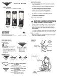
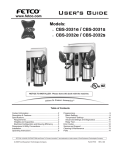
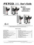
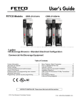
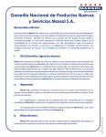
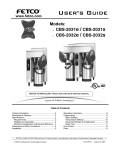
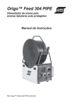
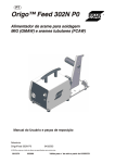
User’s Guide
www.fetco.com
Models: CBS-71A & AC Digital
CBS-72A & AC Digital
CBS-72AT & ATC Digital
Table of Contents
Contact Information ................................................ 2
Description & Features ........................................... 2
Specifications.......................................................... 2
Weights and Capacities ...................................... 2
Electrical Configuration and Brewing Efficiency . 3
Installation............................................................... 5
Operating Procedures ............................................ 8
Brewing System .................................................. 8
Transfer System.................................................. 9
Programming ........................................................ 10
Cleaning & Maintenance ...................................... 11
Parts ..................................................................... 12
FETCO®, and LUXUS® are trademarks or trade names of Food Equipment Technologies Company.
© 2006 Food Equipment Technologies Company
Part # P022
Rev. February 8, 2006
Contact Information
Phone: (800) 338-2699 (US & Canada)
(847) 719-3000
Fax: (847) 719-3001
FETCO®
Food Equipment Technologies Company
600 Rose Road
Lake Zurich • IL • 60047-0429 • USA
Email: [email protected]
[email protected]
Internet: www.fetco.com
Description & Features
CBS-71A - Single Coffee Brewer
CBS-71AC - Single Coffee Brewer
with mobile dispensers
CBS-72A - Twin Coffee Brewer
•
•
•
•
•
•
•
•
CBS-72AC - Twin Coffee Brewer with mobile dispensers
CBS-72AT - Twin Coffee Brewer with
transfer system.
CBS-72ATC - Twin Coffee Brewer with transfer
system and mobile dispensers.
Thermal, portable, stainless steel dispensers, 6, 18, or 24 gallons.
Tight fitting brew baskets seal in flavor and steam.
Fully automatic, with electronic temperature control.
Will not brew unless water temperature is correct.
Thermal breakers and high pressure cutoff switch for safety.
Mercury type power relay.
Total serviceability from the front and top.
72AT/ATC versions: auto or manual transfer to 60 gallon tanks.
Optional Features:
• Power management
• Custom and export voltage
Specifications
Average Brew Time: 7 minutes
Brew Volume: 6 gallons (22.7 liters)
(Not adjustable)
(Allow an extra 3-5 minutes for coffee to finish dripping)
Water Requirements: CBS-71: 1 ½ gpm, 20-75 psig
CBS-72: 3 gpm, 20-75 psig
Coffee Filters: 23” X 9” FETCO # F006
Electrical: See electrical configuration chart.
Weights and Capacities
Brewer
Model
CBS-71A
CBS-72A/AT
Weight
Water Tank
Capacity
Weight
239 lbs.
18 gal.
150 lbs.
420 lbs. 2 X 18 gal. 300 lbs.
Total Weight,
filled
389 lbs.
720 lbs.
2
Dispenser
Weight (empty)
Capacity
Weight (full)
LBD-6
LBD-6C
LBD-18
LBD-24
LBD-60
40 lbs.
152 lbs.
228 lbs.
222 lbs.
227 lbs.
6 gal.
6 gal.
18 gal.
24 gal.
60 gal.
90 lbs.
202 lbs.
378 lbs.
422 lbs.
726 lbs.
Electrical Configuration and Brewing Efficiency
CBS-71A & AC
6.0 gallons per batch
Heater
Configuration
Voltage
Connection
Phase
Wires
KW
Maximum
Amp draw
CBS-71A (-1)
3 X 5 KW
CBS-71A (-2)
3 X 10 KW
CBS-71A (-3)
3 X 10 KW
120/208
120/220
120/240
120/208
120/220
120/240
120/480
3 ph.
3 ph.
3 ph.
3 ph.
3 ph.
3 ph.
3 ph.
4 + ground
4 + ground
4 + ground
4 + ground
4 + ground
4 + ground
4 + ground
11.5
13.3
15.2
22.7
26.3
30.2
30.2
33.0
36.0
37.9
64.3
70.3
74.0
37.9
Model
Batches per Hour (max 5)
Cold Water
Hot Water
3.0
3.3
3.6
4.5
4.8
5.0
5.0
5.0
5.0
5.0
5.0
5.0
5.0
5.0
Batches per hour based on 7 minute
brew time, with no bypass
A and AC versions are actually identical units. The only difference is the stand or counter upon which the unit is
placed.
CBS-72A & AC
Model
CBS-72A (-1)
with power
6.0 gallons per batch
Heater
Configuration
Voltage
Connection
Phase
Wires
KW
Maximum
Amp draw
3 X 5 KW
on each side
120/208
120/220
120/240
120/208
120/220
120/240
3 ph.
3 ph.
3 ph.
3 ph.
3 ph.
3 ph.
4 + ground
4 + ground
4 + ground
4 + ground
4 + ground
4 + ground
11.6
13.4
15.3
22.8
26.4
30.3
33.7
36.7
38.6
65.0
71.0
74.7
4.7
5.4
6.2
6.0
6.6
7.2
10.0
10.0
10.0
10.0
10.0
10.0
3 X 10 KW
on each side
120/208
120/220
120/240
3 ph.
3 ph.
3 ph.
4 + ground
4 + ground
4 + ground
22.8
26.4
30.3
65.0
71.0
74.7
9.3
10.0
10.0
10.0
10.0
10.0
3 X 10 KW
on each side
120/480
3 ph.
3 + ground
30.3
37.9
10.0
10.0
3 X 10 KW
on each side
120/480
60.3
74.7
10.0
10.0
management
CBS-72A (-2)
without power
3 X 5 KW
on each side
management
CBS-72A (-3)
with power
management
CBS-72A (-4)
with power
(plus 120V
cord & plug)
management
CBS-72A (-5)
without power
management
Batches per Hour (max10)
Cold Water
Hot Water
3 ph.
3 + ground
(plus 120V
cord & plug)
Batches per hour based on 7 minute
brew time, with no bypass
Each CBS-72 is actually two separate brewers in one body. Each side has a separate water tank and 3 heaters.
The power management feature allows only one side of the brewer to heat at any given time, which limits the total
amperage required for operation.
A and AC versions are actually identical units. The only difference is the stand or counter upon which the unit is
placed.
3
CBS-72AT & ATC
Model
CBS-72AT (-1)
with power
6.0 gallons per batch
Heater
Configuration
Voltage
Connection
Phase
Wires
KW
Maximum
Amp draw
3 X 5 KW
on each side
120/208
120/220
120/240
120/208
120/220
120/240
3 ph.
3 ph.
3 ph.
3 ph.
3 ph.
3 ph.
4 + ground
4 + ground
4 + ground
4 + ground
4 + ground
4 + ground
11.9
13.7
15.6
23.1
26.7
30.6
35.7
38.7
40.6
67.0
73.0
76.7
4.7
5.4
6.2
6.0
6.6
7.2
10.0
10.0
10.0
10.0
10.0
10.0
3 X 10 KW
on each side
120/208
120/220
120/240
3 ph.
3 ph.
3 ph.
4 + ground
4 + ground
4 + ground
23.1
26.7
30.6
67.0
73.0
76.7
9.3
10.0
10.0
10.0
10.0
10.0
3 X 10 KW
on each side
120/480
3 ph.
3 + ground
30.6
39.9
10.0
10.0
3 X 10 KW
on each side
120/480
60.6
76.7
10.0
10.0
management
CBS-72AT (-2)
without power
3 X 5 KW
on each side
management
CBS-72AT (-3)
with power
management
CBS-72AT (-4)
with power
(plus 120V
cord & plug)
management
CBS-72AT (-5)
without power
Batches per Hour (max10)
Cold Water
Hot Water
3 ph.
3 + ground
(plus 120V
cord & plug)
management
Batches per hour based on 7 minute
brew time, with no bypass
Each CBS-72 is actually two separate brewers in one body. Each side has a separate water tank and 3 heaters.
The power management feature allows only one side of the brewer to heat at any given time, which limits the total
amperage required for operation.
AT and ATC versions are actually identical units. The only difference is the stand or counter upon which the unit is
placed.
Steam Heated Brewers
Model
Maximum
Steam Demand
Steam
Pressure
Volts
Wires
Maximum
Amp draw
Batch
Size
CBS-71A/AC (-4)
80 lbs./hr.
10-15 PSI
120
2 + ground
1.8
6.0 gal.
CBS-72A/AC (-6)
160 lbs./hr.
10-15 PSI
120
2 + ground
2.5
6.0 gal.
Customer supplies one ¾ inch steam line. No power management between sides.
CBS-72A/AC (-7)
80 lbs./hr. per side
10-15 PSI
120
2 + ground
2.5
6.0 gal.
Customer supplies two ½ inch steam lines. No power management between sides.
CBS-72A/AC (-8)
80 lbs./hr.
10-15 PSI
120
2 + ground
2.5
6.0 gal.
Customer supplies one ½ inch steam line. With power management between sides.
CBS-72AT/ATC (-6)
160 lbs./hr.
10-15 PSI
120
2 + ground
4.5
6.0 gal.
Customer supplies one ¾ inch steam line. No power management between sides.
CBS-72AT/ATC (-7)
80 lbs./hr. per side
10-15 PSI
120
2 + ground
4.5
6.0 gal.
Customer supplies two ½ inch steam lines. No power management between sides.
CBS-72AT/ATC (-8)
80 lbs./hr.
10-15 PSI
120
2 + ground
4.5
6.0 gal.
Customer supplies one ½ inch steam line. With power management between sides.
Each CBS-72 is actually two separate brewers in one body.
Each side has a separate water tank and steam coil.
The power management feature allows only one side of the
brewer to heat at any given time, which limits the steam
demand required for operation.
4
Brew
Heads
Maximum
Batches/Hour
1
2
6
10
2
10
2
10
2
10
2
10
2
10
All steam heated brewers are supplied with the
following:
Steam inlet strainer, with ½” FPT
(¾” FPT on CBS-72A/AT (-6) )
Steam trap, with ½” hose barb
Standard 3 wire power cord for 120 VAC outlet.
Installation
(For Qualified Service Technicians Only)
Keys To A Successful Installation
If not installed correctly by qualified personnel, the brewer will not operate properly and damage may result.
Damage resulting from improper installation is not covered by the warranty.
Here are the key points to consider before installation:
Electrical:
• All FETCO brewers require NEUTRAL. Ground is not an acceptable substitute. Installation without neutral
may cause damage to the electronic components.
• The power connection to L1 on the terminal block must be at least 105 volts. Less than 105 volts will
cause erratic behavior from the brewer.
• Push button circuit breakers are located on the front of the brewer, behind the dispensers.
Plumbing:
• This equipment is to be installed to comply with the applicable federal, state, or local plumbing codes.
• The water line must be flushed thoroughly prior to connecting it to the brewer to prevent debris from
contaminating the machine.
General:
• Utilize a qualified beverage equipment service technician for installation.
Brewer Installation
The installation must comply with applicable federal, state, and local codes having jurisdiction at your location.
Check with your local inspectors to determine what codes will apply to the installation and operation of FETCO
products.
Brewer Set-up
• Place the brewer stand (for mobile cart systems) or counter (for stationary systems) in the desired location.
Allow at least 1 foot of space between the wall and the back of the stand or counter.
For easy access and visibility, electrical shut off switches, circuit breakers, water valves, and filters should
not be located directly behind the brewer.
• Using a carpenter’s level, adjust the legs until the stand or counter is perfectly level front-to-back, and leftto-right.
• Each leg has a flange with 2 holes for bolting the stand or counter to the floor (required for safety). Mark
the location of the holes on the floor.
• Set the stand or counter aside, and drill holes in the floor as marked. The materials used will depend on
the floor material.
• Bolt the stand or counter to the floor, and double check to make sure it is level.
• The brewer is shipped lying on its’ back. Before standing it upright, remove the front cover. There is no
need to remove the 2 top covers.
• Place the brewer on top of the stand or counter. This requires at least 3 people, 4 if possible.
• Bolt the brewer to the stand or counter, using the nuts and bolts provided.
Drip Tray Drain Connection (stationary systems only)
• A kitchen sink style drain is provided on the drip tray for connection to a 1 ½ inch drain pipe.
• Before connecting the drain, the customer should select one of the three available height positions for
mounting the drip tray. Holes are provided in the back of the counter for each of the available positions.
Water connection
• Caution! The hose barb fitting(s) protruding from the back of the unit are the tank drains. DO NOT
connect the incoming water to these fittings.
• The water connection is a single 3/8 inch male flare fitting, located inside the lower compartment.
• The brewer can be connected to a cold or hot water line. Cold water is preferred for best coffee flavor, but
hot water will allow for faster recovery times.
5
•
•
•
Install a water shut off valve near the brewer to facilitate service. If an in-line water filter is used, it should
be installed after the water shut off valve and in a position to facilitate filter replacement.
Before connecting the water line to the brewer, flush the line and water filter thoroughly to remove any
debris.
Connect the water line to the brewer, and turn on the water to check for leaks.
Electrical connection
(Steam heated brewers - see next section)
•
•
•
•
•
Verify that the actual voltage at the electrical service connection is compatible with the specifications on the
brewer’s serial number plate. Make sure the electrical service includes neutral.
A fused disconnect switch or circuit breaker on the incoming power line must be conveniently located near
the brewer, and its location and markings known to the operators.
The body of the brewer must be grounded to a suitable building ground. A ground lug is provided in the
brewer next to the power terminal block. Use only 10 gauge copper wire for grounding.
Make sure that both power switches are in the “off” position. The buttons should be in the “out” position.
Connect the power, neutral, and ground wires to the terminals in the brewer.
208-240V
120V
208-240V
208-240V
GROUND
WIRE
TO 120V OUTLET
480 V
CORD WITH 5-15P
NEMA PLUG
N
GROUND
LUG
3
GROUND
LUG
Electrical Connection - 240 volts, 3 phase
•
•
•
480 V
GROUND
WIRE
L1 L2 L3
TERMINAL BLOCK
•
•
480 V
2
1
L1 L2 L3
TERMINAL BLOCKS
GROUND
LUG
Electrical Connection - 480 volts, 3 phase
Turn on the building circuit breaker. Do not turn on the brewer’s power switches yet.
At the brewer’s terminal block, verify that the correct voltage is between terminals, according to the
diagram above.
CBS-71A - press the power switch. CBS-72A - press only the power switch on the brewer’s left side. The
power switch will illuminate. After a delay of 5-6 seconds, the tank should begin filling with water.
CBS-72A - You can press the right side power switch at any time to begin filling the other tank, but this will
cause the first tank to fill more slowly. To fill the first tank as fast as possible, wait until it has filled
completely before pressing the right side power switch.
The heating process will begin after the water has reached a safe level, but before the tank has filled
completely. Approximately 10-15 minutes after the tank has filled, the ready light will illuminate, indicating
that this side of the brewer is at the proper temperature and ready to operate.
Steam Heated Brewers
Electrical connection
• The electrical connection is 120 VAC, single phase, 2 wire plus ground. A power cord with a standard 515P plug is provided. The brewer will draw a maximum of 2.5 amps.
Steam connection
• The steam line must be clean and free of any debris. A shut off valve should be located near the brewer.
• The steam inlet is ½ “ or ¾” FPT, and is equipped with a strainer. There are two steam traps with ½ hose
barbs.
• The steam pressure should be at least 10 PSI, and must not exceed 15 PSI.
• A shut off valve should be located near the brewer.
• To prevent backups, the ends of the hoses connected to the steam traps must be free (not connected or
submerged).
6
Transfer System (AT versions only)
Holding Tank Set-up
• Place the tank stand in the desired location.
• Using a carpenter’s level, adjust the legs until the stand is perfectly level front-to-back, and left-to-right.
• Each leg has a flange with 2 holes for bolting the stand to the floor (required for safety). Mark the location
of the holes on the floor.
• Set the stand aside, and drill holes in the floor as marked. The materials used will depend on the floor
material.
• Bolt the stand to the floor, and double check to make sure it is level.
• Place the holding tank on top of the stand.
• The tank’s rear legs have flanges with 2 holes for bolting the tank down.
• Level the tank, and bolt it to the stand.
• Connect the two stainless steel shielded transfer hoses between the brewer and the holding tank.
Water Connection - Tank Rinse System
• The tank must be connected to a hot water line. A minimum of 50 PSI is required. Before connecting it,
flush the line thoroughly to remove any debris.
• The connection is a ½ inch male flare fitting, located on the left side of the tank, near the bottom. The flare
fitting can be removed, leaving a ½ inch FPT connection.
• Before connecting the water line, make sure that the rinse jet valve on the front of the tank is in the “off”
position. (The tank cover must be in place whenever the rinse jet valve is turned on.)
Tank Overflow Connection
• Connect a ¾ inch I.D. hose to the overflow fitting on the right side of the tank. The opposite end of the
hose should be free, not connected or submerged.
Drip Tray Drain Connection
• A kitchen sink style drain is provided on the drip tray for connection to a 1 ½ inch drain pipe.
7
Operating Procedures
Brewing System
Before brewing, always verify the cleanliness of the brew baskets and dispensers.
1. Push the POWER switch to the ON position
• The button will illuminate to indicate that the brewer has power and is operational.
2. Prepare the brew basket(s).
• Carefully pull open the drawer holding the brew basket.
• Grasp the brew basket by one handle, and turn it until you can reach both
handles comfortably.
• Grasp both handles and lift the basket out of the drawer. If necessary,
empty and rinse the brew basket.
• Place a paper filter in each basket to be used. Pour the appropriate
amount of pre-measured, ground coffee into the filter. Spread the coffee
evenly in the basket until it is a uniform depth. (The amount of coffee used
will depend on your personal tastes and the recommendation of your
coffee supplier.)
• Place the brew basket back into the drawer. Turn the brew basket to align either one of the handles
with either front corner of the drawer.
• Close the drawer completely. When fully closed, it will be flush with the front surface of the brewer.
3. Place the appropriate dispenser(s) in position under the brew baskets.
• Ensure that the brew-through cover is in place, the dispenser is empty enough to handle the amount of
coffee to be brewed, and the faucets are closed.
• Ensure that the dispensers are pushed all the way in, and that the brew funnels are aligned with the
bottom of the brew baskets.
• When using carts, always set both parking brakes by pressing your foot on the paddle just above each
of the two wheels closest to you. When the brakes are set, a green button extends above the paddle.
To release the brakes for moving, press the green button with your foot.
4. When the READY light is on, press the BREW button to start the brew cycle
• The brew cycle will begin immediately, and the BREW button will illuminate. The brew cycle cannot be
started unless the READY light is on.
• Drip delay: When the brew cycle is finished, the BREW button will flash during the drip delay cycle,
indicating that coffee may still be dripping from the bottom of the brew basket.
Optional BREW WAIT setting (See Programming section)
• If the BREW WAIT setting is ON, and the READY light is off when the brew button is pressed, the
BREW and READY lights will begin flashing. When the water has heated to the proper temperature,
the READY light will go on, the brew cycle will begin, and the BREW button will illuminate with a steady
glow.
• If necessary, you may stop the brew cycle at any time by pressing the STOP button. This will reset the
brewer, and you will have to start a new brew cycle from the beginning.
5. The RINSE button (labeled “FLUSH” on some units)
• When this button is pressed, both the brew and bypass valves will open, allowing the maximum
amount of water to flow into the brew basket. Water will flow only while the button is pressed.
• Used primarily to rinse the brew basket at the end of the day, it may also be used to pre-heat the brew
basket before brewing.
• The flow of water will stop if the RINSE button is held in for more than 30 seconds. If a longer rinse
time is desired, release the button momentarily and press it again.
• Caution! If the button is pressed too many times, the dispenser may overflow.
CAUTION:
• Do not remove the brew basket or move the dispensers immediately after the brew cycle has
finished. Wait until dripping from the bottom of the brew basket has stopped. This may take
several minutes.
• When removing the brew basket, carefully inspect the inside of the basket for hot coffee that
may have been trapped or has not finished draining.
• Always set both parking brakes whenever carts are not being transported.
8
Transfer System
1. Before Brewing
• Remove the sight gauge vent cap from the dispenser you want to transfer, and insert the transfer hose
into the top of the sight gauge.
• Ensure that the dispenser, brew basket, and holding tank cover are in place, and that all old coffee has
been drained from the holding tank and dispensers.
• Ensure that the Transfer, Automatic switch is in the “OFF” position, and that the ready light is on.
• Unlock and turn the rinse jet valve on the front of the holding tank to the “on” position to pre-heat the
tank.
• Press and hold the Rinse (or FLUSH) button on each brew head for approximately 30 seconds.
• Press and hold the manual transfer button on each side until the dispensers are empty to pre-heat and
rinse the transfer lines. (The flow of water will stop if the button is held in for more than 30 seconds. If a
longer time is desired, release the button momentarily and press it again.)
• Turn the rinse jet valve to the “off” position.
• Open the lower faucet on the holding tank until the tank has drained completely.
2. Automatic transfer
• Set the Transfer, Automatic push button above the brew head you wish to transfer to the “ON” position.
This can be selected at any time during the brew cycle. The system will wait until the brew cycle is
completed, then automatically transfer the entire contents of the dispenser to the holding tank.
3. Manual transfer
• After a brew cycle has stopped, you can transfer coffee with the manual button in 2 ways:
-Set the Transfer, Automatic switch to the “ON” position, and momentarily press the manual transfer
button. This will start a timed transfer just as if the transfer had been selected during the brew cycle.
-Set the Transfer, Automatic switch to the “OFF” position, and hold the manual transfer button in until the
transfer is complete.
• The flow of water will stop if the manual transfer button is held in for more than 30 seconds. If a longer
transfer time is desired, release the button momentarily and press it again. Repeat as needed.
4. Stopping the transfer
• You can stop the brew and transfer cycles on either side by pressing the appropriate stop button, or by
pressing the appropriate power button to the off position. You can also shut down both sides at the
same time by pressing the emergency stop palm switch in the center of the brewer. If you stop the
brew head in the middle of a brew cycle, you will have to begin a new brew cycle from the beginning.
You cannot restart a brew cycle after it has been stopped. If you stop the brew in the middle of a
transfer cycle, you can finish the transfer by holding in the Transfer, Manual push button.
• Pressing the Emergency stop push button will remove power to the brewer and cancel all functions on
both sides. If the problem can be isolated to one side only, the power switch to the appropriate side
can be turned off and the emergency stop switch reset. This will allow the good side of the brewer to
continue to function.
5. Dispensing coffee from the holding tank
• The upper faucet is positioned to allow coffee to be dispensed at a slower rate than the lower faucet
when the tank is nearly full. It will not drain the tank completely due to its’ position.
• The lower faucet will dispense much faster than the upper faucet and will drain the tank completely.
Use caution, especially when the tank is nearly full.
6. End of the day cleaning
• Ensure that the dispenser, brew basket, and holding tank cover are in place, and that all old coffee has
been drained from the holding tank and dispensers.
• Ensure that the Transfer, Automatic switch is in the “OFF” position, and that the ready light is on.
• Unlock and turn the rinse jet valve on the front of the holding tank to the “on” position.
• Press and hold the Rinse (or FLUSH) button on each brew head for approximately 30 seconds.
• Press and hold the manual transfer button on each side until the dispensers are empty.
(The flow of water will stop if the button is held in for more than 30 seconds. If a longer time is desired,
release the button momentarily and press it again.)
• Turn the rinse jet valve to the “off” position.
• Make one full brew on each side, without coffee in the brew basket, and the Automatic Transfer OFF.
• Manually transfer approximately ½ of the water to the holding tank. This will flush hot rinse water
through the entire system, leaving only clean, fresh water in the pump and lines. Leave the remaining
water where it stands until the system is needed again.
• Remove the brew basket and wipe the area above the basket with a cloth to remove any coffee oils.
9
Programming
f
Turn the power switch on.
CONTROL BOARD
Display
f
Hold the SET button for 3 seconds, until the display reads SET.
SET
f
The display will show 0.0 briefly,
followed by the software version. Example: 10.A
0.0
10.A
f
f
Press SET. The first parameter number will be displayed briefly,
1.0
followed by the current setting.
Example: 1.0 = Brew orifice, .312”
Use the UP and DOWN buttons to adjust the setting.
312
Press SET again. The next parameter will be displayed briefly,
1.1
followed by the current setting.
Example: Bypass percent, 0%
Use the UP and DOWN buttons to adjust the setting.
0
Continue this way until all parameters are programmed.
See the chart below for an explanation of each parameter.
f
Important! To save your changes and return to operating mode,
you must hold SET for 3 seconds until the display reads STo.
2
(Switch stuck or held in for
more than 45 seconds.)
STo
The unit will automatically return to normal operating mode after 30 seconds
without programming activity, and changes will not be saved.
Parameter
1
Error Codes
050 - Shorted Temp Probe
051 - Open Temp Probe
070 - Stuck switch
Error codes are displayed
on the control board.
To reset, turn the power
switch off and on.
f
f
The display shows the
actual water temperature
when not in Programming
mode.
Name
0.0
1.0
Software Version
Brew orifice size
1.1
Bypass Percent
1.2
Range
Increment
Standard Factory
1
Setting
Five available
sizes: .250,
.281, .312,
.343, .375.
0.00 – 35.0%
.312
5%
0%
Drip Delay
(Min:Sec)
1 – 5 minutes
10 sec.
1:30
1.3
Auto Transfer Pump
1 – 6 minutes
10 sec.
4:00
2.0
3.0
Water Temp. (°F)
Brew Wait
180°F - 208°F
ON - OFF
1°F
205°F
OFF
Standard factory settings apply unless custom settings were requested at the time of order.
Non-standard size brew orifices must be ordered from FETCO.
10
Comment
Displays current version.
This is the size of the hole in
the brew orifice, which
controls how fast water is
dispensed.2
Percentage of total brew
volume.
Time between the end of the
brew cycle and the brew light
stops flashing.
Transfer units only.
This is the amount of time the
transfer pump runs after a
brew cycle when the “Auto
Transfer” switch is on.
OFF = Brewer must be at set
temperature (READY light on)
to start a brew cycle.
ON = If the BREW button is
pressed when the unit is not
at the set temperture, the
brewer will wait until it heats
up, and then begin brewing.
The READY and BREW lights
flash during the waiting time.
Cleaning & Maintenance
Daily
Before brewing, always verify the cleanliness of the brew baskets and dispensers.
At the end of the day, remove the brew basket and wipe the bottom of the spray pan with a cloth to remove the
coffee oils that have collected.
Brew & Bypass Orifices
The flow of water through the brew and bypass orifices may gradually become restricted by the accumulation of
mineral deposits. The orifices should be inspected periodically and cleaned if necessary.
To remove the orifices:
•Remove the brew basket and brew basket drawer.
•Grasp the sides of the spray pan with both hands and turn it counter-clockwise. Being careful not to drop
it, continue turning it with both hands until it comes completely off.
•The brew orifice is located in the center of the threaded piece that held the spray pan. The bypass orifice
is located to the right and to the rear of the brew orifice. Both orifices are stainless steel. Do not remove
the brass fitting located in the same area. This is the vent from the water tank.
•Removal of either orifice requires a 11/16 inch wrench.
•Replace or clean the orifices and reassemble all of the parts.
Transfer Systems: End of the day cleaning
•
•
•
•
•
•
•
•
•
Ensure that the dispenser, brew basket, and holding tank cover are in place, and that all old coffee has
been drained from the holding tank and dispensers.
Ensure that the Transfer, Automatic switch is in the “OFF” position, and that the ready light is on.
Unlock and turn the rinse jet valve on the front of the holding tank to the “on” position.
Press and hold the Rinse (or FLUSH) button on each brew head for approximately 1 minute.
Press and hold the manual transfer button on each side until the dispensers are empty.
Turn the rinse jet valve to the “off” position.
Make one full brew on each side, without coffee in the brew basket, and the Automatic Transfer in the
OFF position.
Manually transfer approximately ½ of the water to the holding tank. This will flush hot rinse water
through the entire system, leaving only clean, fresh water in the pump and lines. Leave the remaining
water where it stands until the system is needed again.
Remove the brew basket and wipe the area above the basket with a cloth to remove the coffee oils that
have collected.
11
Parts
Figure 1 – CBS-72A Main Assembly
# 92 & 94 - SEE NOTE
12
NOTE: #92 & 94 ARE WELDED TOGETHER. ORDER PART# 002077 - DISPENSE VALVE FITTING WELDMENT
13
Figure 2 – CBS-72A Tank Assembly
ITEM #
1
1
1
10
31
32
33
34
40
41
53
61
63
65
66
QTY
PART #
DESCRIPTION
3
3
3
4
1
1
1
2
1
1
4
3
1
1
1
107010
107009
107008
84002
31121
31113
58035
33016
31054
31104
83035
31118
102114
83041
31123
ASSEMBLY, IMMERSION HEATER, 5000W, 240VAC
ASSEMBLY, IMMERSION HEATER, 10000W, 480VAC
ASSEMBLY, IMMERSION HEATER, 10000W, 240VAC
NUT, HEX, 8-32
NIPPLE, PIPE, 1/8", 4.25"LG
COUPLING 1/8"
SWITCH, PRESSURE, 2PR
LOCKNUT, 1-1/16"
FITTING, 1/2 HOSE BARB X 3/8 MPT
FITTING, EXTRUDED FPT ELBOW, 3/8 X 3/8
WASHER, #8 LOCK
LOCKNUT, 3/8"
THERMAL CIRCUIT BREAKER
WASHER, 0.812" O.D X 0.412 I.D
FITTING, MALE CONNECTOR 1/2 X 3/8
14
67
68
69
70
71
72
73
74
76
77
78
79
80
81
82
83
85
86
87
89
123
124
125
126
127
128
131
132
133
134
136
137
138
148
149
150
151
1
1
1
2
1
1
1
1
1
1
1
1
1
1
1
1
1
1
1
1
1
1
1
1
4
2
2
1
1
2
1
1
1
1
1
1
1
32054
002229
002050
21026
102115
24014
004020
31116
31074
83041
31120
31122
33014
33015
31114
31021
31082
34004
31054
31101
102279
32059
31027
002072
86016
31055
57001
31119
25050
86015
25053
25054
25051
54029
24057
13091
31036
TUBE, THERMAL CIRCUIT BREACKER
WELDMENT, WATER LEVEL PROBE, 9,0" LG
WELDMENT, WATER LEVEL PROBE, 2.5" LG
HOUSING, WATER LEVEL PROBE
ASSEMBLY, TANK COVER
GASKET, TANK
WELDMENT, TANK, CBS-72
LOCKNUT, 1/8"
FITTING, 3/8 HOSE BARB X 3/8 MALE PIPE 90 DEG ELBOW
WASHER, 0.812 O.D X0.412I.D. FLAT
FITTING, 1/8 STREET 90 DEG. ELBOW
NIPPLE, PIPE, 1/8"
FITTING, TANK BREW VALVE
FITTING, TANK, BY-PAS
FITTING, ELBOW, EXTRUDED, 90 DEG
BUSHING, 3/4-16X 1/4,NPSM HEX HEAD
FITTING, HEX NIPLE, 3/8MPT X 1/4 MPT
VALVE, BALL, 3/8
FITTING, 1/2 HOSE BARB X 3/8 MPT
FITTING, BARB 1/2 HOSE I.D. X 3/8 MPT
ASSEMBLY, DIGITAL TEMP. PROBE, 14" LG, W/52" CABLE
TUBE, COLD WATER
FITTING, COMPR.90DEG ELBOW, 3/8TUBE O.D.X 1/4MPT
WELDMENT, TANK WATER INLET TUBE
CLAMP, WPRM DRIVE, HEYCO, 0.562-1.062
FITTING, ELBOW, 3/8COMPR. X 3/8 MPT
VALVE, S-45, 120VAC, 3/8 NPTX 3/8 NPT91.35GAL/MIN)
FITTING, FLARED TEE, 3/8 MPT X 3/8 MPT X 3/8 TUBE O.D.
TUBE, VENT, .375 I.D. X .655 O.D.X 13.5 LG
CLAMP, WORM DRIVE, HEYCO, 1.062-1.25
TUBE, BY-PASS, .500 X .800 X 3.375" LG
TUBE, BREW VALVE, .625 X .965 X 8.625 LG
TUBE, DRAIN, 3/8 X 5/8 X 10.0" LG
SENSOR, DIGITAL TEMP. PROBE, W/52" CABLE
PLUG, RUBBER, DIGITAL TEMP. PROBE
HOUSING DIGITAL TEMPERATURE PROBE, 14.0" LG
FITTING, COMPR. MALE CONNECTOR, 1/4 TUBE X 1/4 MPT
15
Figure 3 – CBS-72A Brew Basket Assembly
ITEM #
QTY
14
15
16
18
19
21
22
1
1
1
3
3
0
0
PART #
002069
09011
101134
21076
83025
82044
102113
DESCRIPTION
SPRAY PAN, CBS-70'S
WIRE BASKET, CBS-70'S
BREW BASKET ASSEMBLY, CBS-70'S
BREW BASKER HEIGHT REGULATOR
SPRING LOCK WHASER, 1/4"
STAINLESS STEEL HEX CAP SCREW, 1/4-20 X 1.0"LG
DRAWER ASSEMBLY, CBS-70'S
16
Figure 4 – LBD-6C Assembly
17
ITEM #
QTY
PART #
1
2
3
4
5
6
7
8
9
10
11
12
13
14
15
16
17
18
19
20
21
22
23
24
25
26
27
28
29
30
31
32
33
34
34
1
1
1
1
1
6
1
1
1
1
1
1
2
4
1
4
4
8
1
1
1
1
1
1
1
1
2
1
1
1
1
1
1
1
1
24015
22016
04054
84028
24016
72007
13039
01340
83025
82055
82012
003007
13096
001028
71025
71024
71018
002068
21034
87009
71017
71036
72018
13015
13014
31045
71026
71037
LBD-6 COVER ASSEMBLY
6 GAL. DISPENSER FUNNEL
1.00'' I.D. X 1.25 O.D. O-RING
LBD-6 VENT SCREW
DISPENSE COVER TOP
3/8''X 1/2'' S.S. PAN HEAD PHIL. SCREW
SEALING TAPE
CBS-70'S 6GAL. DISPENSE COVER GASKET
6 GAL. DISPENSER INSULATION SET
LBD-6 GAL.DISPENSER COVER BOTTOM
5/6-18 NYLON INSERT LOCKNUT
6 GAL.DISPENSER LINER GASKET
6 GAL. DISPENSER HANDLE
HANDLE STAND OFF (SMALL)
6 GAL. DISPEPENSER TOP
1/4 S.S. LOCKWASHER
1/4 - 20 X 3/4'' HEX HD. CAP SCREW
3/16'' DIA. SEALING BLIND RIVET
6.GAL. DISPENSER WELDMENT
SHANK, LINER, LBD-6
LBD-6 BODY WELDMENT
SHIELD CUP PLUG #44
SHIELD CUP
GAUGE UPPER WASHER
GAUGE HOUSING WELDMENT
GAUGE TUBE 11.5''
5/32 DIA. X .270 L. POP BLIND RIVET
LOWER GAUGE WASHER
C-RING
6GAL. MOBILE DISPENSER LOCK
3/4-20 SHANK LOCKNUT
1.5 GAL. SHANK W GAUGE NEST
1/2 NPS UNION NUT
FAUCET, COMPLETE, ES SERIES
FAUCET UPPER ASSY.
34
34
34
35
36
37
38
39
40
41
42
43
44
45
46
1
1
1
1
2
2
2
2
2
1
4
4
2
1
4
71035
71028
71027
01336
84015
83019
83020
01329
72008
001028
72012
01437
101164
83019
83020
FAUCET SEAT CUP
FAUCET HANDLE, BLACK
FAUCET HANDLE, ORANGE
CBS-71 COUNTER OR 6GAL.SERV.CART DRIP TRAY
5/16-18 HEX NUT
5/16'' FLAT WASHER
5/16 LOCKWASHER
6 GAL. SERVING CART SINK
SERVING CART HANDLE
6 GAL. SERVING CART WELDMENT
6 GAL. DISPENS. COVER KNOB
6 GAL. DISPENSER COVER LOCK
LBD-6 ASSY
5/16'' FLAT WASHER S.S.
5/16'' SPRING LOCK WASHER
102111
23044
24034
13050
04053
82032
DESCRIPTION
(INCLUDES BLACK HANDLE, SEAT CUP, SPRING, BONNET)
18
47
48
49
50
51
52
53
54
55
56
57
58
4
1
8
8
8
2
1
1
2
1
1
1
84015
73024
84022
83031
83032
73025
14011
82063
06010
82042
72006
82041
5/16''-18 HEX NUT
6 GAL. CONTEINER CASTER, SWIVEL
3/8-16 MACHINE SCREW NUT
3/8'' S.S FLAT WASHER
3/8'' REGULAR SPRING LOCKWASHER
6 GAL. CONTAINER CASTER
LBD-6C BALANCE WEIGHT
3/8-16 X 12'' HEX HD. CAP SCREW ZINC PLATED
FUNNEL COVER
ROUND BEAD CHAIN FITTING #8-10
FUNEL CUP KNOB
#6 ROUND CHAIN
19