1
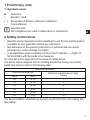
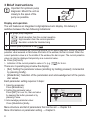
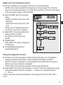
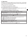
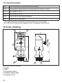
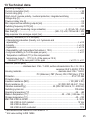
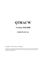
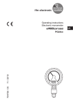
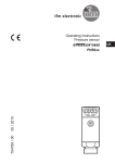
Operating instructions
Combined sensor for pump diagnosis
and pressure monitoring
706058 / 00
04 / 2014
PIM093
PIM094
UK
Contents
1 Preliminary note���������������������������������������������������������������������������������������������������3
1. Symbols used���������������������������������������������������������������������������������������������������3
2 Safety instructions������������������������������������������������������������������������������������������������3
3 Brief instructions ��������������������������������������������������������������������������������������������������4
4 Functions and features�����������������������������������������������������������������������������������������6
5 Function����������������������������������������������������������������������������������������������������������������6
5.1 Processing of the measured signals��������������������������������������������������������������6
5.2 Pump monitoring��������������������������������������������������������������������������������������������7
5.3 Pressure monitoring/ analogue function���������������������������������������������������������8
5.4 Pressure monitoring / switching function��������������������������������������������������������9
6 Installation����������������������������������������������������������������������������������������������������������10
7 Electrical connection������������������������������������������������������������������������������������������12
8 Operating and display elements�������������������������������������������������������������������������13
9 Menu������������������������������������������������������������������������������������������������������������������14
9. 1 Menu structure��������������������������������������������������������������������������������������������14
9. 2 Menu explanation ���������������������������������������������������������������������������������������15
10 Parameter setting���������������������������������������������������������������������������������������������16
10.1 Parameter setting general��������������������������������������������������������������������������16
10.2 Configuring unit for pump diagnosis�����������������������������������������������������������18
10.3 Configuring unit for pressure monitoring����������������������������������������������������20
10.4 User settings (optional) �����������������������������������������������������������������������������21
10.5 Service functions����������������������������������������������������������������������������������������22
11 Operation����������������������������������������������������������������������������������������������������������23
11.1 Read the set parameter values�������������������������������������������������������������������23
11.2 Changing the display in the Run mode�������������������������������������������������������23
11.3 Fault indication��������������������������������������������������������������������������������������������24
12 Scale drawing ��������������������������������������������������������������������������������������������������24
13 Technical data���������������������������������������������������������������������������������������������������25
13.1 Setting ranges��������������������������������������������������������������������������������������������26
14 Factory setting��������������������������������������������������������������������������������������������������27
2
1 Preliminary note
1. Symbols used
►
>
[…]
→
Instruction
Reaction, result
Designation of buttons, switches or indications
Cross-reference
Important note
Non-compliance can result in malfunctions or interference.
UK
2 Safety instructions
• Read the product description before installing the unit. Ensure that the product
is suitable for your application without any restrictions.
• Non-adherence to the operating instructions or technical data can lead to
personal injury and/or damage to property.
• In all applications check compliance of the product materials (→ chapter 13
Technical data) with the media to be measured.
For units with cULus approval and the scope of validity cULus:
The device shall be supplied from an isolating transformer having a secondary
Listed fuse rated as noted in the following table.
Overcurrent protection
Control-circuit wire size
AWG
(mm2)
26
(0.13)
24
(0.20)
22
(0.32)
20
(0.52)
18
(0.82)
16
(1.3)
Maximum protective device rating
Ampere
1
2
3
5
7
10
The Sensor shall be connected only by using any R/C (CYJV2) cord, having suitable ratings.
3
3 Brief instructions
Important for optimum pump
diagnosis: Mount the unit as
closely to the spout of the
pump as possible.
Display and operation
The unit features an integrated 4-digit alphanumeric display. On delivery it
switches between the two following indications:
1
Bar graph pump diagnosis:
= small deviation from the normal operation
= high deviation from the normal operation
= deviation outside the tolerated rang
2
Current system pressure in bar
The bar display visualises the monitoring window for the pump diagnosis. When the current
pulsation value exceeds or falls below the limits of the window, the bar is closed. When the
current pulsation value is in the middle of the window, the bar is open. The current pulsation
value can also be displayed temporarily as a numerical value.
►► Press [Set] briefly.
>> Indication of the current pulsation value in % (e.g.
) for 4 min.
There are 2 operating keys below the display:
• [Set]: Setting the parameter values (scrolling by holding pressed); incremental
by pressing briefly).
• [Mode/Enter]: Selection of the parameters and acknowledgement of the parameter values.
Each parameter setting requires 3 steps:
1. Selecting parameter:
Press [Mode/Enter].
2. Setting the parameter value:
Press [SET] for over 5 s, then set value
by keeping the button pressed or by
pressing it once.
3. Acknowledge parameter value:
Press [Mode/Enter] briefly..
Menu structure and list of parameters that can be set → chapter 9.2.
More information on parameter setting → chapter 9.
4
Adjust unit to the installation (teach)
►► Put the installation into operation and use it in normal operation.
NOTE: For the teach operation the pressure must be at least 5% of the final
value of the measuring range. For a safe teach operation 10% of the final value
of the measuring range is recommended.
►► Select [PUMP], set the requested
value:
-- [FAST] for fast pumps (more than
200 rpm);
UK
-- [SLOW] for slow pumps (40...300
rpm).
Pumps with a rotational speed be
low 40 rpm cannot be monitored.
►► Select [tPu1], then press [Set] and
keep the button pressed.
>> [tch] flashes, first slowly, then
quickly.
►► Release [Set].
>> After approx. 20 s [tch] is displayed
continuously.
►► Press [Mode/Enter] briefly (=
acknowledgement).
Testing the diagnostic function
►► Put the unit into the operational status at which the alarm is to be triggered.
Change several times between normal operation and faulty operation.
If OUT1 remains unchanged in normal operation but switches in the event of
faults, the process has been completed.
If OUT1 does not switch as requested: make a fine adjustment:
►► Select [SEn1] and set a value between 1 and 20. The value indicates the upper
and lower tolerance limits for pulsation; 1 = lowest, 20 = highest tolerance
(→ 10.2.4).
Further menu items for the optimisation of the diagnostic function: HSP, LSP →
10.2.7.
5
4 Functions and features
The unit monitors the operating state of pumps and the system pressure of
machines and installations.
Applications
Type of pressure: relative pressure
Order no.
PIM093
PIM094
Measuring range
bar
-1...25
-1...10
PSI
-14.4...362.7
-14.5...145
Permissible
Bursting pressure
overload pressure
bar
PSI
bar
PSI
100
1 450
350
5 070
50
725
150
2 175
MPa = bar ÷ 10 / kPa = bar × 100
Static and dynamic overpressures exceeding the indicated overload pressure are to be avoided by taking appropriate measures.
The indicated bursting pressure must not be exceeded. Even if the bursting pressure is exceeded only for a short time, the unit can be destroyed.
NOTE: Risk of injury!
5 Function
5.1 Processing of the measured signals
• The unit analyses the pulsation characteristics of the pump and signals the
deviations from the basic characteristic determined for normal operation.
• It detects the system pressure and evaluates the measuring signal.
2 outputs are available for the signal output:
• Output 1:
-- Signal for pump diagnosis; adjustable window function, normally open or
normally closed.
• Output 2:
2 configuration options:
-- Analogue signal proportional to the pressure (4...20 mA or 20...4 mA, scaleable).
-- Switching signal for the system pressure; adjustable to hysteresis or window
function, normally open or normally closed.
6
5.2 Pump monitoring
When pumps are operated, pulsation patterns occur in the pressure pipe. They
are high-frequency minimum pressure fluctuations superimposing the standard
curve of the system pressure.
The pulsation pattern depends on the operating status of the pump. In normal
operation a characteristic standard pattern occurs. It changes under non-standard
operating conditions.
Examples for non-standard operating conditions:
• cavitation (due to reduced cross-section, e.g. filter clogging, closed slide or low
UK
supply pressure),
• air/gas inclusion, partial running dry or running dry,
• wear of the pump,
• blockage of the pump.
Evaluation of the pulsation pattern
display
output function
Pu = numerical value pulsation.
Pu1 = mean value of pulsation in normal operation. The value is defined by the teach process (→ 10.2.2), however, it can also be entered manually (→ 10.2.7). It does not have
any effect on the output; it only controls the bar display (for pulsation value = Pu1 the
bar is open).
HSP1 = upper limit value, LSP1 = lower limit value for the pulsation. The values are automatically defined during the teach process, however, they can also be entered manually (→
10.2.7). With pulsation ≥ HSP1 or pulsation ≤ LSP1 the bar is closed.
SEn1 = tolerance range for pulsation (symmetrical with the teached pulsation value Pu1).
Fno = OUT1 in normally open operation (Out1 = ON if the value increases above HSP1 and
decreases below LSP1); Fnc = OUT1 in normally closed operation.
The graphics display is independent of the setting for OUT1.
7
• The pulsation pattern occurred in normal operation is detected. It is converted
into a numerical value (Pu1) which the unit stores as the standard value; bar
graph: closed
.
• The standard value can be fixed automatically by teaching or manually
(→ 10.2).
• During operation the pulsation pattern is constantly monitored. If it is different
from the standard value and exceeds the tolerance range SEn1 (= the defined
limits HSP1 and LSP1), output 1 changes its switching status; the bar graph
.
closes
• The switching signals can be directly used for maintenance or active pump
control.
5.3 Pressure monitoring/ analogue function
The analogue signal can be set:
• [OU2] defines whether the set measuring range is provided as a 4...20 mA
signal ([OU2] = [I]) or a 20...4 mA signal ([OU2] = [InEG]).
• [ASP] defines the measured value at which the output signal is 4 mA (20 mA at
[InEG]).
• [AEP] defines the measured value at which the output signal is 20 mA (4 mA at
[InEG]).
Minimum distance between [ASP] and [AEP] = 25 % of the final value of the
measuring range (turn down 1:4).
Factory setting
Measuring range scaled
P = system pressure, MAW = initial value of the measuring range, MEW = final value of
the measuring range
1 : [OU2] = [I]; 2 : [OU2] = [InEG]
8
In the set measuring range the output signal is between 4 and 20 mA / 20 and
4 mA.
Also signalled:
• System pressure above the measuring range:
-- output signal > 20 mA at [OU2] = [I],
-- the output signal drops to maximum 3.8 mA at [OU2] = [InEG].
• System pressure below the measuring range:
-- the output signal drops to maximum 3.8 mA at [OU2] = [I],
-- output signal > 20 mA at [OU2] = [InEG].
UK
5.4 Pressure monitoring / switching function
OUT2 changes its switching state if it is above or below the set switching limits
(SP2, rP2). The following switching functions can be selected:
• Hysteresis function / normally open: [OU2] = [Hno] (→ fig. 1).
• Hysteresis function / normally closed: [OU2] = [Hnc] (→ fig. 1).
First the set point (SP2) is set, then the reset point (rP2) at the requested distance.
• Window function / normally open: [OU2] = [Fno] (→ fig. 2).
• Window function / normally closed: [OU2] = [Fnc] (→ fig. 2).
The width of the window can be set by means of the distance between SP2 and
rP2. SP2 = maximum value, rP2 = minimum value.
1
2
P = system pressure; HY = hysteresis; FE = window
9
6 Installation
Ensure that no pressure is applied to the installation while mounting or
removing the sensor.
►► Install the unit as closely as possible to the spout of the pump. Only
then will the pulsation pattern be
optimally transferred to the unit.
10
Aseptoflex adapters ensure that the
sensor can be connected to different
process connections.
(The adapters have to be ordered
separately as accessories.)
Mounting operation:
►► Mount the adapter (C) to the sensor.
►► Fix sensor + adapter by means of
a coupling nut, a clamp flange or
similar (B) to the process connection.
If it is not possible to slide the fixing
element (B) down over the top of the
sensor: slide it up over the bottom
of the sensor before the adapter is
mounted.
A = rotatable housing
Mounting the Aseptoflex adapter
1
2
3
UK
►► Slightly grease the threads and sealing areas of the sensor and adapter with
lubricating paste (D).
The paste must be suitable and approved for the application and compatible
with the elastomers used.
Recommendation: Klüber paste UH1 84-201 with USDA-H1 approval for the
food industry.
►► Make sure that the O-ring (E) is correctly positioned.
►► Screw the sensor into the adapter until it is hand-tight. Do not damage the sealing chamfers.
►► Clamp sensor and adapter into a clamping device (F). Tighten the clamping
device only slightly so that the adapter does not warp.
►► Tighten the sensor using a spanner until you can feel the end stop (corresponding to a maximum tightening torque of 25 Nm / 18 ftlb). Note: Do not overtighten. This can have an adverse effect on the sealing.
NOTE: A guarantee for a long-term stable and maintenance-free fitting with no bug
traps in the hygienic sealing of the metal seal (Aseptoflex connection) is only valid
for once-only mounting.
11
Welding adapter
►► First weld the adapter, then mount the sensor. Follow the instructions included
with the adapter.
7 Electrical connection
The unit must be connected by a qualified electrician.
The national and international regulations for the installation of electrical
equipment must be adhered to.
Voltage supply to EN50178, SELV, PELV.
►► Disconnect power.
►► Connect the unit as follows:
Pin 1
Pin 3
Pin 4 (OUT1)
Ub+
Ubbinary switching output for pump diagnosis
signal for pressure monitoring
Pin 2 (OUT2) •analogue output if [OU2] = [I] or [InEG]
•binary output if [OU2] = [Hno], [Hnc], [Fno] or [Fnc]
Core colours of ifm sockets:
1 = BN (brown), 2 = WH (white), 3 = BU (blue), 4 = BK (black)
12
8 Operating and display elements
UK
1 - 8: Indicating LEDs
-- LED 1: green = indication of the system pressure in bar.
-- LED 2: green = indication of the system pressure in MPa.
-- LED 3: green = indication of the system pressure in PSI.
-- LED 4: not used.
-- LED 5: green = display mode “bar graph for pump diagnosis” is active.
-- LED 6: not used.
-- LED 7: yellow = output 2 (pressure monitoring) is switched.
-- LED 8: yellow = output 1 (pump diagnosis) is switched.
9: Alphanumeric display, 4 digits
 ↔
, if [SELd] =
-- System pressure and bar graph are indicated alternately:
[P Pu] is set.
-- Bar graph for pump diagnostics (if [SELd] = [Pu] is set).
= small deviation from the normal operation.
= high deviation from the normal operation.
= deviation outside the tolerated range.
-- Indication of the system pressure (if [SELd] = [P] is set; e.g.
).
-- DispIay of the parameters and parameter values.
10: Set pushbutton
-- Setting of the parameter values (scrolling by holding pressed, incremental by pressing
briefly).
-- Changing the display unit in the Run mode → 11.2.
11: Mode/Enter pushbutton
-- Selection of the parameters and acknowledgement of the parameter values.
13
9 Menu
9. 1 Menu structure
14
9. 2 Menu explanation
PUMP
tPu1
Setting to the rotational speed range of the pump monitored.
).
Standard value for teaching the pulsation. (
Sensitivity of pump monitoring (tolerance limits for not reaching / exceeding
SEn1
the standard value).
Switching function for OUT1 (pump diagnosis): window function / normally
OU1
open [Fno] or window function / normally closed [Fnc].
Output function for OUT2 (monitoring the system pressure):
•Switching signal for the limit values: hysteresis function [H ..] or window
OU2
function [F ..], normally open [. no] or normally closed [. nc] each.
UK
•Analogue signal for the current system pressure: 4-20 mA [I] or 20-4 mA [InEG].
Analogue start point for the system pressure: measured value at which 4 mA
ASP
are output (20 mA on OU2 = InEG).
Analogue end point for the system pressure: measured value at which 20 mA
AEP
are output (4 mA / on OU2 = InEG).
SP2 / rP2 Upper / lower limit value for the system pressure.
EF
Extended functions / Opening menu level 2.
dAPu Damping the pulsation value.
HSP1 Upper switching limit for pulsation value (
PU1 Average pulsation value (
).
).
LSP1 Lower switching limit for pulsation value (
).
dS1 Switch-on delay for OUT1.
dr1 Reset delay for OUT1.
PumF Read / enter the characteristic value for the pulsation frequency.
dAP Damping of the measured value for the signal “pressure monitoring”.
dS2 Switch-on delay for OUT2.
dr2 Reset delay for OUT2.
dAA Damping for the analogue signal “system pressure”.
HI Maximum value memory for the system pressure.
LO Minimum value memory for the system pressure.
COF Zero point calibration.
Uni Standard unit of measurement for the system pressure.
Display mode: system pressure or bar graph for pump diagnosis or change
SELd
between them.
diS Update rate and orientation of the display.
rES Restore the factory setting.
15
10 Parameter setting
During the parameter setting process the unit remains in the operating mode. It
continues its monitoring function with the existing parameters until parameter setting has been terminated.
10.1 Parameter setting general
Each parameter setting requires 3 steps:
1
Selecting parameter
►► Press [Mode/Enter] until the requested parameter is displayed.
2
Setting the parameter value
►► Press [Set] and keep the buton
pressed.
>> Current setting value of the parameter bit flashes for 5 s.
>> After 5 s: Setting value is changed:
incremental by pressing briefly or
scrolling by holding pressed.
The numerical values are incremented continuously. If the value is to be reduced: Let
the display move to the maximum setting value. Then the cycle starts again at the
minimum setting value.
3 Acknowledge parameter value
►► Press [Mode/Enter] briefly.
>> The parameter is displayed again.
The new setting value is stored.
Set more parameters:
►► Start again with step 1.
Finishing parameter setting:
►► Press [Mode/Enter] several times until the current measured value is displayed or wait
for 15 s. The unit returns to the operating mode if no button is pressed for over 15 s
after acknowledgement of the new parameter value.
16
• Changing from menu level 1 to menu level 2:
►► Press [Mode/Enter] until [EF] is
displayed.
►► Press [Set] briefly.
>> The first parameter of the submenu is
displayed (here: [dAPu]).
UK
• Locking / unlocking
The unit can be locked electronically to prevent unintentional wrong settings.
►► Ensure that the unit is in the normal
operating mode.
►► Press [Mode/Enter] + [Set] for 10 s.
>> [Loc] is displayed.
During operation: > [Loc] is displayed briefly when you try to change parameter values.
For unlocking:
►► Press [Mode/Enter] + [Set] for 10 s.
>> [uLoc] is displayed.
On delivery: Unlocked.
• Timeout:
If no button is pressed for 15 s while the parameters are being set, the unit returns to
the operating mode with unchanged values.
17
10.2 Configuring unit for pump diagnosis
10.2.1 Adjusting to the pump
►► Select [PUMP], set the requested value:
[FAST] for fast pumps (more than 200 rpm);
[SLOW] for slow pumps (40...300 rpm).
Pumps with a rotational speed below 40 rpm cannot be monitored.
10.2.2 Teaching the normal value
►► Put the installation into operation and use it in normal operation.
NOTE: If teaching is carried out at pressures below 10 % of the final
value of the measuring range, the diagnostic function may provide
wrong values.
►► Select [tPu1], press [Set] and keep the button pressed.
>> [tch] flashes, first slowly, then quickly.
►► Release [Set].
>> >After approx. 20 s [tch] is displayed continuously.
If [UL] is displayed, the system pressure for a teach operation is too low
(system pressure < 5% of the final value of the measuring range). The
process was stopped.
►► Press [Mode/Enter] briefly (= acknowledgement).
>> The mean pulsation value in normal operation (Pu1), the tolerance
range (SEn1) and thus the limits of the monitoring window HSP1 and
LSP1 are defined.
10.2.3 Testing the diagnostic function
►► Put the unit into the operational status at which the alarm is to be triggered. Change
several times between normal operation and faulty operation.
If OUT1 remains unchanged in normal operation but switches in the event of faults,
the process has been completed. If OUT1 does not switch as requested: Make fine
adjustments(→ 10.2.4 / 10.2.6 / 10.2.7).
18
10.2.4 Adapting the sensitivity (optional)
►► Select [SEn1] and set a value between 1 and 20. The value determines
the upper and lower tolerance limit for pulsation (→ fig. 10.2.2; 1 = lowest, 20 = highest tolerance).
►► Test function again, adjust SEn1 value, if required, or optimise the
diagnostic function → 10.2.7.
10.2.5 Setting the output signal
►► Select [OU1] and set the switching functions:
[Fno] = window function / normally open,
[Fnc] = window function / normally closed.
Optional: Set the switch-on delay [dS1] or the reset delay [dr1]:
►► Select [dS1] or [dr1], set value between 0.1 and 50.0 s (at 0.0 the delay
time is not active).
10.2.6 Dampen process value “pulsation” (optional)
Goal: Stabilise the switching characteristics and the bar graph.
►► Select [dAPu] and set value between 0.1 and 50.0 s (0.0 = [dAPu] is not
active).
dAPu value = time during which the pulsation increases to 63% of the
maximum value.
10.2.7 Optimising the diagnostic function (optional)
Only if required: If deviations are not always safely detected.
►► Put the installation into operation and use it in normal operation.
►► Press [Set] briefly.
>> The current pulsation values are displayed for 4 minutes (if [SELd] = [P
Pu]; → 10.4.2).
►► Watch the display during this time. Note down the average value, the
maximum value and the minimum value.
►► Select [HSP1] and enter the upper limit value for the monitoring window
(→ fig. 10.2.2). It has to be greater than or equal to the maximum value
noted down.
The more HSP1 is above the minimum value noted down, the larger the
tolerance against fluctuations of the pulsation value.
►► Select [Pu1] and enter the mean value noted down. It does not have
any effect on the output; it only controls the bar display (for pulsation =
Pu1 the bar is open).
continue → next page
UK
19
Select [LSP1] and enter the lower limit value for the monitoring window
(→ fig. 10.2.2). It has to be smaller than or equal to the minimum value
noted down.
The more LSP1 is below the minimum value noted down, the larger the
tolerance against fluctuations of the pulsation value.
ATTENTION: [HSP1] always has to be greater than [Pu1], [LSP1] always
has to be smaller than [Pu1].
If a value to be newly entered is greater or smaller than the neighbouring
value, the neighbouring value has to be changed accordingly beforehand.
Examples: If a value is to be entered for [Pu1] that is greater than the current value for [HSP1], the HSP1 value has to be increased beforehand.
If a value is to be entered for [HSP1] that is smaller than the current value
for [Pu1], the Pu1 value has to be decreased beforehand.
10.3 Configuring unit for pressure monitoring
10.3.1 Setting the output function
►► Select [OU2] and set the function:
[Hno] = hysteresis function / normally open,
[Hnc] = hysteresis function / normally closed,
[Fno] = window function / normally open,
[Fnc] = window function / normally closed.
[I] = current signal proportional to the pressure 4…20 mA,
[InEG] = current signal proportional to the pressure 20…4 mA.
10.3.2 Scaling the analogue value
►► Select [ASP] and set measured value at which 4 mA are output (20 mA
at [OU2] = [InEG]).
►► Select [AEP] and set measured value at which 20 mA are output (4 mA
at [OU2] = [InEG]).
Minimum distance between ASP and AEP = 25 % of the final value of the
measuring range (scaling factor 1:4).
Optional: Damping analogue signal “system pressure”:
►► Select [dAA] and set value between 0.01 and 10.00 s (at 0.00 [dAA] is
not active).
dAA value = response time between pressure change and change of the
analogue value in seconds.
20
10.3.3 Setting the switching limits
►► Select [SP2] and set the measured value at which the output switches.
►► Select [rP2] and set the measured value at which the output switches
back.
rP2 is always lower than SP2. The unit only accepts values which are lower
than SP2.
Optional: Damping the switching signal “pressure monitoring”:
►► Select [dAP] and set value between 0.01 and 10.00 s (at 0.00 = [dAP]
is not active).
dAP value = response time between pressure change and change of the
switching status in seconds.
[dAP] influences the switching frequency: fmax = 1 ÷ 2dAP.
Optional: Fix switch-on delay [dS2] or reset delay [dr2]:
►► Select [dS2] or [dr2], set value between 0.1 and 50.0 s (at 0.0 the delay
time is not active).
UK
10.4 User settings (optional)
10.4.1 Setting the standard unit of measurement for the system pressure
►► Select [Uni] and set the unit of measurement: [bAr], [MPA] or [PSI].
10.4.2 Configuring the display
►► Select [SELd] and set the type of display:
[P]: System pressure in the unit set in Uni
.
[Pu]: Bar graph for pump diagnosis
.
[P Pu]: System pressure / bar graph for pump diagnosis alternately
↔
.
►► Select [diS] and set update rate and orientation of the display:
[d1]: Update of the measured value every 50 ms.
[d2]: Update of the measured value every 200 ms.
[d3]: Update of the measured value every 600 ms.
[rd1], [rd2], [rd3]: Display like d1, d2, d3; rotated by 180°.
[OFF]: The display is deactivated in the operating mode.
10.4.3 Zero-point calibration
►► Select [COF] and set a value between -5% and 5% of the final value of
the measuring range. The internal measured value “0” is shifted by this
amount.
21
10.5 Service functions
10.5.1 Reading the min./max. values for the system pressure
►► Select [HI] or [LO], press [Set] briefly.
[HI] = maximum value, [LO] = minimum value.
Delete memory:
►► Select [HI] or [LO].
►► Press [SET] until [----] is displayed.
►► Press [MODE/ENTER] briefly.
10.5.2 Reset all parameters to the factory setting
►► Select [rES], then press [SET] until [----] is displayed.
►► Press [MODE/ENTER] briefly.
It makes sense to note down your own settings before executing the function (→ 14 Factory preset).
10.5.3 Read / enter the characteristic value for the pulsation
frequency
►► Select [PumF] and press [SET] briefly.
►► Read the value and note it down(→ 14 Factory preset).
When the unit has been replaced, it can be stored in the new unit:
Select [PumF], activate via [Set], enter numerical value.
22
11 Operation
After power on of the supply voltage the unit is in the Run mode (= normal operation). It carries out its measurement and evaluation functions and generates output
signals according to the set parameters.
11.1 Read the set parameter values
►► Press [Mode/Enter] briefly to scroll the parameters.
►► Press [Set] briefly to indicate the corresponding parameter value for 15 s. After
another 15 s the unit returns to the Run mode.
11.2 Changing the display in the Run mode
When alternating indication is selected (
↔
►► Press [Set] briefly.
>> Indication of the current pulsation value in % (e.g.
When pressure indication is selected (
; [SELd] = [P PU]):
) for 4 min.
; [SELd] = [P]):
►► Press [Set] briefly.
>> Indication of the deviation of the pulsation from the normal operation for 4 min.
= small deviation from the normal operation.
= high deviation from the normal operation.
= deviation outside the tolerated range.
When the bar graph is selected (
; [SELd] = [Pu]):
►► Press [Set] briefly.
>> Indication of the current system pressure (e.g.
) for 4 min.
23
UK
11.3 Fault indication
[OL]
overload pressure (measuring range exceeded)
[UL]
underpressure range (measuring range below the minimum value)
[SC1]
short circuit in OUT1*
[SC2]
short circuit in OUT2*
[SC]
short circuit in both switching outputs*
[Err]
internal fault, invalid input
*The output concerned is switched off as long as the short circuit exists.
[SC1], [SC2], [SC] and [Err] are displayed even if the display is switched off.
12 Scale drawing
Dimensions are in millimeters
1: Display
2: LEDs
3: Programming button
4: Aseptoflex sealing edge
5: Aseptoflex thread
24
13 Technical data
Operating voltage [V]............................................................................................ 18...32 DC
Current consumption [mA]...............................................................................................< 50
Current rating [mA]...........................................................................................................250
Short-circuit / reverse polarity / overload protection, integrated watchdog
Voltage drop [V].................................................................................................................< 2
Power-on delay time [s].................................................................................................... 0,2
Min. response time switching outputs [ms]........................................................................2,5
Switching frequency OUT2 [Hz].......................................................................................350
Analogue output (measuring range scaleable)..................................... 4...20 mA / 20...4 mA
Max. load [Ω].....................................................................(UB - 10) x 50; 700 bei UB = 24V UK
Step response time analogue output [ms].........................................................................0,2
Accuracy / deviation (in % of the span)1)
- Characteristics deviation (linearity. incl. hysteresis and
repeatability)2) ...........................................................................................................< ± 0.2
- Linearity...................................................................................................................< ± 0.15
- Hysteresis................................................................................................................< ± 0.15
- Repeatability (with temperature fluctuations < 10 K).................................................< ± 0.1
- Long-term stability (in % of the span per year).........................................................< ± 0.1
- Temperature coefficient (TC) in the compensated
temperature range 0 ... 70°C (in % of the span per 10 K)
- Greatest TC of the zero point / of the span........................................... < ± 0.15 / < ± 0.1
Materials (wetted parts)
................................ stainless steel 316L / 1.4435, surface characteristics: Ra < 0.4 / Rz 4
ceramics (99.9 % Al2O3); PTFE
Housing materials.................................................................... stainless steel 316L / 1.4404;
PC (Makrolon); PBT (Pocan); PEI; FPM (Viton); PTFE
Protection ........................................................................................................IP 67 / IP 69K
Protection class...................................................................................................................III
Insulation resistance [MΩ]..........................................................................> 100 (500 V DC)
Shock resistance [g]................................................................ 50 (DIN / IEC 68-2-27, 11ms)
Vibration resistance [g].................................................. 20 (DIN / IEC 68-2-6, 10 - 2000 Hz)
Switching cycles min............................................................................................ 100 million
Operating temperature [°C]................................................................................... -25 ... +80
Medium temperature [°C]............................................................. -25...+125 (+145 max. 1h)
Storage temperature [°C]...................................................................................... -40...+100
EMCEN 61000-4-2 ESD:.........................................................................................4 / 8 KV
EN 61000-4-3 HF radiated:............................................................................... 10 V/m
EN 61000-4-4 Burst:.............................................................................................2 KV
EN 61000-4-6 HF conducted:............................................................................... 10 V
1)
all indications are referred to a turn down of 1:1
2)
limit value setting to DIN 16086
25
13.1 Setting ranges
Upper (SP2) / lower limit value (rP2) for the system pressure; analogue start point
(ASP) / analogue end point (AEP) for the system pressure
PIM094
PIM093
SP2
rP2
ASP
ΔP
min
max
min
max
min
max
min
max
bar
-0.96
25.00
-1.00
24.96
-1.00
18.74
5.24
25.00
0.02
PSI
-13.8
362.7
-14.4
362.1
-14.4
271.8
76.2
362.7
0.3
MPa
-0.096 2.500 -0.100 2.496 -0.100 1.874 0.524 2.500 0.002
bar
-0.98
10.00
-1.00
9.98
-1.00
7.50
1.50
10.00
0.01
PSI
-14.2
145.0
-14.5
144.7
-14.5
108.7
21.8
145.0
0.1
MPa
-0.098 1.000 -0.100 0.998 -0.100 0.750 0.150 1.000 0.001
ΔP = increments
Parameters for pump diagnosis
SEn1
Pu1
HSP1
LSP1
min
max
min
max
min
max
min
max
1
20
1
799.9
1.1
800
0
799.8
26
AEP
14 Factory setting
Factory setting
PUMP
SEn1
OU1
OU2
ASP
AEP
SP2
rP2
dAPu
HSP1
Pu1
LSP1
ds1
dr1
PumF
dAP
ds2
dr2
dAA
COF
Uni
SELd
dis
User setting
FAST
3
Fnc
I
0% VMR*
100% VMR*
25% VMR*
23% VMR*
3.0
800.0
640.0
480.0
0.0
0.0
3
0.06
0.0
0.0
0.00
0.0
bAr
P Pu
d2
UK
* = the indicated percentage of the final value of the measuring range (VMR) of the corresponding sensor in bar is set
More information at www.ifm.com
27